Welcome to Our Community

Some features disabled for guests. Register Today.

Core-XY Cube

Discussion in '3D printers' started by alan richard, Jun 15, 2016.
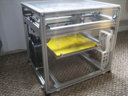
  1. alan richard

    Builder

    Joined:
    Sep 27, 2014
    Messages:
    12
    Likes Received:
    41
    alan richard published a new build:

    Read more about this build...
     
  2. James Archer

    Builder

    Joined:
    Mar 16, 2015
    Messages:
    9
    Likes Received:
    15
    Very nice build! I like the enclosed design and the sturdy metal construction, I would like to build something like this next.

    Do you think your bowden set-up could handle flexible filaments? this is concern I am having with my current build.
     
  3. Mark Carew

    Mark Carew OpenBuilds Team
    Staff Member Moderator Builder Resident Builder

    Joined:
    Jun 28, 2013
    Messages:
    2,741
    Likes Received:
    2,407
    Great job on this one @alan richard great looking machine . I am a big fan that its enclosed nice an neat and can be picked up and taken with you so easily.
    Thanks for sharing this with us. :thumbsup:
     
  4. alan richard

    Builder

    Joined:
    Sep 27, 2014
    Messages:
    12
    Likes Received:
    41
    Thanks Gents. Appreciate the praise.
    The goal was a printer that was fairly shock-proof and transportable and built as a 'consumer product' Mark.
    Interesting Skeleton build, James. look forward to seeing it progress. I don't think flexible filaments get on with bowden extruders very well but it looks like you have the head room to fit a direct extruder if you need it.
     
    Mark Carew likes this.
  5. Ramjet

    Ramjet New
    Builder

    Joined:
    Aug 2, 2016
    Messages:
    5
    Likes Received:
    0
    Alan;
    What Version of Solidworks do you run? I only have 2013.
    Can you save everything as parasolids?
    Then I could load them no matter what version you have.

    Thanks
     
  6. alan richard

    Builder

    Joined:
    Sep 27, 2014
    Messages:
    12
    Likes Received:
    41
    Hello Ramjet.
    Its only modeled as a non-parametric AutoCAD file. SW should open its native .dwg

    a
     
  7. Noah Wille

    Builder

    Joined:
    Aug 18, 2016
    Messages:
    1
    Likes Received:
    0
    Hi just curious if I could get a better picture of your timing belt apparatus for the X and Z axises. Looking to build a printer and want to know how you positioned them.
     
  8. alan richard

    Builder

    Joined:
    Sep 27, 2014
    Messages:
    12
    Likes Received:
    41
    Hi Noah.
    Excuse the delay. I've been away from PC.
    If you can get a CAD viewer like Autodesk's DWG trueView and have a look at the attached CAD file, that may help.
    I'll add some images for you, maybe later today.
    Regards
    a
     
  9. alan richard

    Builder

    Joined:
    Sep 27, 2014
    Messages:
    12
    Likes Received:
    41
    Maybe this will help-
    [​IMG]


    [​IMG]

    -a
     
    Noah Wille and Kyo like this.
  10. Michael.M

    Michael.M Veteran
    Staff Member Builder Resident Builder

    Joined:
    Jan 21, 2017
    Messages:
    432
    Likes Received:
    263
    Very clean looking machine. If I didn't already have a printer, I would definitely consider building this. Great job! Thanks for sharing.
     
  11. Andrew Burgess

    Builder

    Joined:
    Jan 27, 2018
    Messages:
    20
    Likes Received:
    1
    Would you be able to generate a set of drawings (PDF format) for this device? I have a final project that I need to do and everyone seems to be using anything BUT Solidworks. I have 7 weeks to get my **** together.
     
  12. CoreCube3D

    Builder

    Joined:
    Mar 19, 2018
    Messages:
    12
    Likes Received:
    13
    @alan richard,
    This is very wonderful and very inspiring in my own attempt to build a similar machine. In fact once I saw this I decided to follow it fairly closely as it matches many ideas I had about a rigid framed corexy based model, and parts I have on hand.

    I have a few questions if you are still here and able to answer. Do you still use this system and how is it holding up after what appears to be 1.5 years? What might you change to improve it?

    What was your reason for having one xy belt above (motor up) and one below (motor down)? I realize the belts need to be offset slightly but I would have chosen to have them only slightly offset on the same side of the xy plane but I may be missing something important. Since I'm currently ordering parts and going to build a very similar printer it would be great to have clarity on this arrangement.

    Thanks, and great looking system!
     
  13. alan richard

    Builder

    Joined:
    Sep 27, 2014
    Messages:
    12
    Likes Received:
    41
    Thanks core. Glad you like it. Someone PM'd a similar question & I said;

    The printer has worked out well and has been quite dependable almost 3 years now.
    It doesn't get loads of use, once or twice a week average but fairly plug and play. No maintenance. Robust.

    I could say that I wouldn't really want to change anything.

    One issue that I did correct was the way the X axis fixes to its wheel plates. I originally had 2 small angle brackets above and below the X axis but this wasn't rigid enough. The X axis had 4 adjustable Alu blocks which hold the belt rollers, I made 2 of these longer to butt against the wheel plates and screwed thru the plate.
    It did mean that the width of X axis was no longer adjustable and the rollers were fixed position, I think an L shaped bracket from the sides of the X extrusion to the plate in 4 positions would have been better.

    Things that were awkward during build/ setup but are not an issue now;
    The belt clamps could be improved, I stripped a thread on one and chopped a belt short on a sharp edge.
    The X & Y motor mounting is really fiddly and awkward to adjust but it does keep it compact and uses a stock bracket.*

    The Z axis is a bit over constrained with 4 linear bearings, 3 would have done, as one of them is fairly loose now.
    It started out with just 2 bearings on a more shallow bed but that had too much play.

    There was a bit of resonant noise in the box at some motor speeds. I did later take the x and y motors off and fitted 'astrosyn' type rubber motor mounts which are very good. 1/32 microstepping makes a big difference too.

    If I made another
    No max endstops or so many wires to the head. I would have used fewer silicon insulated cables and a smaller cable chain.
    A mains powered silicon bed heater and a smaller 12v PSU.
    V slot for the Z axis as well with a single 80x20 (or 2x 40's) extrusion in the middle, maybe 6 wheels
    Option for a direct drive

    The extruder (a 3D printed 'airtripper') has worked quite reliably. I did fit a higher torque stepper at one point.
    That long bowden is fine for ABS/ PLA but not really suited to flexible or rough stuff like woodfill.


    *The X & Y motor mounting - 2 of the screw heads on the steppers end up hidden in the top of the extrusion.
    It needs the motor fitted to the bracket first, then fix the bracket to the frame with hex screws & T nuts with a thin spanner between the motor and bracket.


    In answer to belt offsets - The idea was that one part of the belt loop on both sides would run inside the channel of the 40mm v-slot. One side in the upper and the other lower. which makes it 20mm spacing. If you bring the belt path away from the v slot then the offset can be any distance. One motor 'up' and one 'down' just worked out ok with the brackets I was using.

    Glad you like it. I'm happy to help with any questions.

    Regards
    Alan
     
  14. CoreCube3D

    Builder

    Joined:
    Mar 19, 2018
    Messages:
    12
    Likes Received:
    13
    Thank you so much for your detailed answer. I'm just at the stage now of ordering parts and materials so it will be weeks before things arrive and I start building. One thing I had already decided was to use AC silicone heating due to how much power would need to be pushed through the PSU. Funny though because I thought you had a large SSR for this reason and I was copying you. It is incredibly helpful to see your working version as a model to work from because it adds more certainty to my outcome as long as I don't deviate too much. Anyway, I may get back in touch if I have questions while trying to build later.

    Thank you again for even just putting this project here for others (me) to see and work from. I've browsed many designs online but yours just hit closest to what I had in mind. :)
     
  15. CoreCube3D

    Builder

    Joined:
    Mar 19, 2018
    Messages:
    12
    Likes Received:
    13
    Maybe you know this already but I just thought I'd mention it. The first youtube video is not viewable in UK, USA or Australia (my location) due to copyright content (SME apparently, whatever that is). I tried some proxies and was able to view through one in Germany so did get to see it. It could be that most people who try to view it cannot and why it has half the views compared to second one.
     
  16. alan richard

    Builder

    Joined:
    Sep 27, 2014
    Messages:
    12
    Likes Received:
    41
    Thanks for telling me. I didn't know that.
    It may be the music on there. I'll see if I can change it.
    The SSR in the vid. burn't out I think it was the terminal to it, High current 12V will find any resistance in a connection and turn it into heat.
    Nice one. All the best.
     
  17. CoreCube3D

    Builder

    Joined:
    Mar 19, 2018
    Messages:
    12
    Likes Received:
    13
    I have the same SSR on order (or a copy maybe as it's ebay). Did it go out in a bang/flash or just stop working?

    According to the data sheet it will turn on above 2.5V with only 7.5 mA current so it shouldn't have much flowing through it. It's probably just not that high quality internally - though it did last a few years I guess. Maybe it's worth adding a current limit resistor on the input so even if it does short it won't damage the MOSFET on the control board if it happens again. Say, (12-3)V / 0.02A ~= 470 ohms, 1/2W should work.

    I have most of my aluminum frame pieces, MKS Gen-L control board, 2 steppers, psu, j-head and extruder assembly already and another ~50 packages on the way arriving over the next few weeks.

    Thanks for the update info.
     
  18. alan richard

    Builder

    Joined:
    Sep 27, 2014
    Messages:
    12
    Likes Received:
    41
    The low volt MOSFET side of mine was fine, it was the switched side to the bed. It didn't bang it just stopped. It's the current that kills em but with mains AC its not so high.
    SSR's for switching AC and DC are different.

    BTW The Youtube thing - thanks again, it was the music copyright that was blocking it. Funny thing is that I could watch it ok myself. YT lets you overdub a video with their freeware music so its up there now for all to see with new 'ambient' soundtrack.
    The video was just my way of gathering up all the pics and images in one place. Some of it could run a bit faster.

    I'm excited for you with all your parts arriving. It's nice when jiffy bags full of goodies are coming through the letter box. Have fun, take your time, get it square.
    Cheers

    Alan
     
  19. CoreCube3D

    Builder

    Joined:
    Mar 19, 2018
    Messages:
    12
    Likes Received:
    13
    Excellent. I'll check it out again. I thought it was fine as far as speed. It's probably depends on how interested the viewer is in the details. I've done up a simple cad drawing of mine now to try and ensure I get holes drilled / cuts right the first time. You really have to think 3D to make sure you don't put something where it will block the moving parts.

    I'm totally enjoying between 2-8 pkgs. each day and look forward to the mail now. I have a few projects ongoing so at one point I had over 100 items in bound. :)
     
  20. cybercricket

    Builder

    Joined:
    Sep 9, 2018
    Messages:
    1
    Likes Received:
    0
    I say buy a tronyz x5s kit, gut the electronics literally dump and replace the controller board to a smothieboard, stepper motor replace w Nema 23 with a a aluminum rod for bracing, a torch Stabilize the frame a bit ,also have cnc made all metal parts made custom from a local machine shop. let them know to give u a pro type discount lol. But in all Great information youve provided, Thanks Friends , Really enjoy your post and will try it out on Tronyx x5s i just orderd
     
  21. alan richard

    Builder

    Joined:
    Sep 27, 2014
    Messages:
    12
    Likes Received:
    41
    Interesting. I'd not seen the tronxy before. Good starting point and most of what you want is there already. The frame does look like it could use some bracing as you say. Big print area.

    I don't think that you really need Nema 23's though - 17's should give more that enough torque & speed for printing. I'd suggest trying out the stock motors first.

    CNC machining - definitely would have been better than angle grinder/ hacksaw and my wonky hand filing.

    Thanks for the compliments, glad you like it. Enjoy your project
     
  22. jjfawkes

    jjfawkes New
    Builder

    Joined:
    Dec 19, 2018
    Messages:
    2
    Likes Received:
    0
    Alan, can you please post more details on how you assembled the acrylic sheet with magnets? I really want to make the same setup with the acrylic, since I also have corner cubes, but I don't understand what exactly you did to get it working.
    I understand you put 10mm magnets inside the cubes, but what did you do with the acrylic corners?
    Thanks
     
  23. alan richard

    Builder

    Joined:
    Sep 27, 2014
    Messages:
    12
    Likes Received:
    41
    Hi JJ. Merry Christmas. I've not been online for a few days . . .
    The acrylic was 4mm thick. I drilled it with a 10mm drill until the tip was just about to break thru' and that gave me 2mm recess for the magnets,
    I probably gave them a dab of superglue but they were a nice snug fit. The magnets just squeeze inside the black cover caps of the corner cubs.
    I have to say they've worked out really well. Not fallen off and strong enough to hold the covers in place.
    I did print a couple of supports (you may see them in white, STL attached) that screw to the underside of the base extrusions that stop the side covers slipping down.
    Happy building!

    Alan
     

    Attached Files:

  24. jjfawkes

    jjfawkes New
    Builder

    Joined:
    Dec 19, 2018
    Messages:
    2
    Likes Received:
    0
    Thank you! I will give it a try
     
  25. crgrove

    crgrove New
    Builder

    Joined:
    Sep 27, 2019
    Messages:
    1
    Likes Received:
    1
    Wow! This is an excellent design.

    Although I was a tinkerer when I was a young man, life (and depression) got in the way. Fast forward to the present and I'm learning that creating and building and being a "Maker" helps healing.

    I have a couple cheapie 3D printers right now but I'd like to be able to have an enclosed "high temperature", all-metal printer to print polycarbonate, PEEK and such, regularly without the warping issues that many have.

    Is the filament spool actually WITHIN the enclosure? (I assume easy enough to move outside)

    Would this be a good printer for such high temperature materials, in your opinion?

    Thanks! :)
     
    Peter Van Der Walt likes this.
  26. PassiveAggressor

    Builder

    Joined:
    Aug 20, 2023
    Messages:
    3
    Likes Received:
    0
    Hey did you cut your extrusions using your jigsaw? How did you get your cuts to be straight if do
     

Share This Page

  1. This site uses cookies to help personalise content, tailor your experience and to keep you logged in if you register.
    By continuing to use this site, you are consenting to our use of cookies.
    Dismiss Notice