Welcome to Our Community

Some features disabled for guests. Register Today.

Charging Ox CNC Machine

Discussion in 'CNC Mills/Routers' started by Motions, Jan 10, 2015.
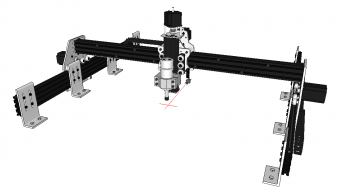
  1. Motions

    Motions Well-Known
    Builder

    Joined:
    Dec 26, 2014
    Messages:
    53
    Likes Received:
    49
  2. Mark Carew

    Mark Carew OpenBuilds Team
    Staff Member Moderator Builder Resident Builder

    Joined:
    Jun 28, 2013
    Messages:
    2,741
    Likes Received:
    2,407
    Awesome strong looking build @Motions.
    Your SketchUp skillz are amazing for just learning it!
    Thank you for sharing your build and we looking forward to seeing the Charging OX take his first steps! :thumbsup:
    Mark
     
  3. Serge E.

    Serge E. Journeyman
    Builder

    Joined:
    May 6, 2014
    Messages:
    730
    Likes Received:
    251
    Interesting build. I like it ...

    Did you think of turning the L brackets around so the 'tab' tying to the plywood goes outward instead of inward ? It should give a clean surface for your other layers (ex: spoil board). They would still hold the V-slot from the inside, just the legs would be outward ... The 'riser' could also have an 'alignment/hold' hole - horizontal screw or even just a tight pin wedged into the spoil board layer ?

    Is the plywood apt to 'move' with humidity and such over time ? Maybe the shaking of the 'Charging OX' could affect rigidity with time and use ? Is it screwed down through the plywood and into more wood or whatnot ?

    Getting the two Y V-slot parallel was probably no worse than with the regular OX approach, eh ?

    I also passed some wiring through the V-slot beams in myOX. But I didn't add any holes, I used the existing openings (a bit tighter, but still plenty of room). I also used Chris' plates (great plates). My mistake was not using connectors on the ends of cabling ... When I had to take things apart, it was a pain to cut and splice as needed. At least I had left (too much) extra length in wires.

    Looking forward to seeing your Charging OX ... running.
     
  4. Motions

    Motions Well-Known
    Builder

    Joined:
    Dec 26, 2014
    Messages:
    53
    Likes Received:
    49
    I actually have the L brackets turned outwards on my current SO2 machine. The reason I'm turning them around is to gain more table area next to the machine plus, since the router can't go all the way to the edge anyway, I can cut down my spoil board to fit between the brackets.

    My table is made from 4x4 and 1" plywood with hefty bracing. I also epoxied the entire top of the table to make it completely flat. I have about 1/8" epoxy layer. The 1/4x20 bolts go through the table with large washers and lock nuts underneath. I did all this to try to get a solid flat base to help with aligning and squaring.

    I have been soldering all my wires and it's a pain when I tear stuff apart. I have Molex connectors for everything but I'm waiting until I get a setup that will stay more than a week. :D

    The Y rails on the SO2 are spread apart and it's a horrible design. I bought an extra 20x40 to bolt between them but it was too much work modifying spacers and such. That's when I decided to build the Ox.
     
  5. Serge E.

    Serge E. Journeyman
    Builder

    Joined:
    May 6, 2014
    Messages:
    730
    Likes Received:
    251
    Nice ... Let's see that Charging OX run.
     
  6. GrayUK

    GrayUK Openbuilds Team Elder
    Staff Member Moderator Builder

    Joined:
    May 5, 2014
    Messages:
    1,668
    Likes Received:
    627
    Excellent job so far. :thumbsup::thumbsup:
    Love the exploded views. :thumbsup:
    We welcome any more you can do. :)

    Well done
    Gray
     
  7. oni305

    oni305 Well-Known
    Builder

    Joined:
    Jan 16, 2014
    Messages:
    106
    Likes Received:
    85
    I like this!
    In fact, I had the same idea!
    I have also created 4 corners to put at the ends of the vslot to increase the lateral resistance
     
  8. Motions

    Motions Well-Known
    Builder

    Joined:
    Dec 26, 2014
    Messages:
    53
    Likes Received:
    49
    Finished build today. Updated build with some photos and video.
     
    sgspenceley and Nick W like this.
  9. Nick W

    Nick W Well-Known
    Builder

    Joined:
    Oct 22, 2014
    Messages:
    99
    Likes Received:
    61
    Looks great.
     
  10. Motions

    Motions Well-Known
    Builder

    Joined:
    Dec 26, 2014
    Messages:
    53
    Likes Received:
    49
    Finally added a video of the Ox actually cutting something. See update in the build.
     
    Larry_AK likes this.
  11. oni305

    oni305 Well-Known
    Builder

    Joined:
    Jan 16, 2014
    Messages:
    106
    Likes Received:
    85
    I can't see the video (private video)
     
    #11 oni305, Feb 1, 2015
    Last edited: Feb 1, 2015
  12. Motions

    Motions Well-Known
    Builder

    Joined:
    Dec 26, 2014
    Messages:
    53
    Likes Received:
    49
    Fixed. Not a fan of using Youtube and I forgot to hit publish.
     
  13. oni305

    oni305 Well-Known
    Builder

    Joined:
    Jan 16, 2014
    Messages:
    106
    Likes Received:
    85
    very cool!
     
  14. xLORDxSIDIUSx

    Builder

    Joined:
    Feb 12, 2015
    Messages:
    2
    Likes Received:
    0
    This build has inspired me to build an ox. What control board are you using?
     
  15. Motions

    Motions Well-Known
    Builder

    Joined:
    Dec 26, 2014
    Messages:
    53
    Likes Received:
    49
    I'm using TinyG for control and driver. I've been very happy with the TinyG and Nema 23 combo. The machine is VERY strong and rock solid.
     
    xLORDxSIDIUSx likes this.
  16. Quy

    Quy New
    Builder

    Joined:
    Aug 26, 2014
    Messages:
    3
    Likes Received:
    1
    Very nice! I'm also inspired to build an OX after seeing this. I'm still working on my SO2 just at the squaring phase and then wiring.

    Where did you source the L Brackets? I couldn't find it listed in the xls file.
    Do you have a rough amount on how much this build cost you?

    In regards to wiring, you could use Cat5e or Cat6 cabling to connect the steppers. I've used them on the lasersaur project (2x4) laser cutter where Cat5e STP was used. I used Cat6 UTP on a Delta 310mm x 400mm 3D printer with thick 14 AWG power lines running in parallel to the cables and haven't had any issues on a 24hr print job. I'm planning on doing the same with the SO2 to allow for future upgrades by just disconnecting the steppers and replacing the cabling with longer cabling.

    Before that I had to figure out if it was feasible to shell out and upgrade the SO2 to a 1000 x 1000mm version or just build a 2nd unit. Building a 2nd unit makes more sense after seeing this.

    Thanks for sharing.
     
  17. Motions

    Motions Well-Known
    Builder

    Joined:
    Dec 26, 2014
    Messages:
    53
    Likes Received:
    49
    I thought the L brackets might be confusing but didn't think anyone else would go that route. The aluminum L bracket is the second item on the parts list. It's a 4' long bracket that I cut into individual brackets and had slots machined in them. They are not off the shelf items. I'm sure Chris Laidlaw could make these very fast and easy.

    I was originally going to try Cat5 for the steppers but with Nema23, I didn't want to take a chance with small gauge wire. I went with some 18AWG 4 conductor cable.
     
  18. Quy

    Quy New
    Builder

    Joined:
    Aug 26, 2014
    Messages:
    3
    Likes Received:
    1
    I think the L brackets are a good idea. I saw it used in another machine called the CNC mogul and in a video where the CNC machine is being used with a drag knife.


    The laser cutter uses both Nema 17 and 23 powered by Cat 5e STP cabling. With network cable you need to double up the conductors. 8 wires = 4 pairs to match 4 wire steppers. There is one guy in the Lasersaur community with over 3000 hours using Cat 5e cabling running Nema 17 & 23 steppers.
     
    Burly Notch Woodshop likes this.
  19. eagle2284

    eagle2284 New
    Builder

    Joined:
    Sep 8, 2014
    Messages:
    11
    Likes Received:
    3
    I originally built the OX to the (almost) standard design. Seeing how you mounted your Y Axis rails to the table inspired me to change my design. I searched everywhere for brackets that would be suitable and it was difficult. I ended up sourcing them from a company I deal with frequently at work that handles aluminum extrusion. Unfortunately I do not think I am at liberty to share my contact for this piece.
    The only problem I am having is torsion on the 1.5m X Axis gantry. Do you have any troubles with this? I can grab the end of the spindle and push it (along the Y Axis) and there is a flex of about 1.0 mm both directions. This affects both the Z Axis and Y Axis measurements. I've already bolted the two X Axis rails together and I am considering filling the extrusions with some form of epoxy or resin.
     
  20. Joao

    Joao New
    Builder

    Joined:
    Jul 14, 2014
    Messages:
    5
    Likes Received:
    0
    Is it possible to share plates drawings?

    Very nice build, thank you.
     
  21. Motions

    Motions Well-Known
    Builder

    Joined:
    Dec 26, 2014
    Messages:
    53
    Likes Received:
    49
    I haven't really seen any deflection in the X rails. I bolted them together super tight. Yours is much longer than mine so I would think there would definitely be some bending to a span that long. I do have a very slight deflection in the Z axis/spindle but very small. This was the primary reason I replaced my Shapeoko. It was not rigid at all.

    Too bad they don't have any 60x40 Vslot rails.
     
  22. Motions

    Motions Well-Known
    Builder

    Joined:
    Dec 26, 2014
    Messages:
    53
    Likes Received:
    49
    Which plates are you referring to? The L brackets? I can add that to the project files. The brackets don't need to be precise in any way. You just have to carefully measure when installing.
     
  23. Derrick_CNC

    Builder

    Joined:
    Jan 27, 2015
    Messages:
    1
    Likes Received:
    0
  24. shali85

    shali85 New
    Builder

    Joined:
    Feb 20, 2015
    Messages:
    3
    Likes Received:
    0
    In agreement with KRam242, your Sketchup skills are impressive.
    Very inspiring build and very neat. Yea! a cost estimate would be great.
    I wonder will you be able to cut a stronger material like Alu on this?
     
  25. Motions

    Motions Well-Known
    Builder

    Joined:
    Dec 26, 2014
    Messages:
    53
    Likes Received:
    49
    Thanks for the compliment. I'm not sure how well it will do with Aluminum because the spindle still has some deflection on harder material. I can see this really good when I get chatter in the bit. I do plan to try out some Alu at some point just to see how it does.

    I have to wait for my new spindle to come in before trying anything though. This weekend I broke my spindle shaft in half. Not sure what happened but I think my 1/4" bit came loose and dug a huge pocket down to the spoil board.
     
  26. SatMike

    SatMike New
    Builder

    Joined:
    Feb 12, 2015
    Messages:
    27
    Likes Received:
    5
  27. Valery

    Valery New
    Builder

    Joined:
    Feb 25, 2015
    Messages:
    1
    Likes Received:
    0
    Hi, should you send us more details like weight, speed, working dimensions (x,y,z) and step accuracy (x,y,z) ? Many thanks.
     
  28. Joao

    Joao New
    Builder

    Joined:
    Jul 14, 2014
    Messages:
    5
    Likes Received:
    0
    Sorry for the late reply! Im talking about the main plates, i think they are similiar to the ones on OX Build.
    Im moddeling your build on Solidworks but the plates i got from the OX build are not very accurate. The dimmensions are atrange.

    [​IMG]
     
  29. Motions

    Motions Well-Known
    Builder

    Joined:
    Dec 26, 2014
    Messages:
    53
    Likes Received:
    49
    The plates are identical to the original Ox build except for the added hole in the cross brace. Which plates seem inaccurate, the Ox build or mine?
     
  30. Joao

    Joao New
    Builder

    Joined:
    Jul 14, 2014
    Messages:
    5
    Likes Received:
    0
    Hi, OX plates, im getting measures in Cad and the dimmensions are all mess up.. im sharing the model in here after this if its ok with you.
     

Share This Page

  1. This site uses cookies to help personalise content, tailor your experience and to keep you logged in if you register.
    By continuing to use this site, you are consenting to our use of cookies.
    Dismiss Notice