Welcome to Our Community

Some features disabled for guests. Register Today.

BlackBox X32

Discussion in 'Other Builds' started by OpenBuilds, Nov 23, 2022.
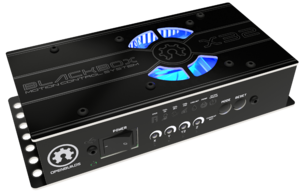
  1. BASt_NL

    BASt_NL New
    Builder

    Joined:
    Sep 9, 2022
    Messages:
    12
    Likes Received:
    3
    Just setting up my X32 controller after switching from another brand of controller (and it seems like @Shell M. Shrader has done exactly the same ;) )

    I have a few questions;
    1. I have the Kress / AMB Digital 1400 FME-P DI which has the option to set speed through the 0-10V
      However, the line goes from 0..1V to 9..10V , see attached picture
      AMB_0-10V.jpg
      $30 Max spindle speed RPM = 25000
      $31 Min spindle speed RPM = 3500
      If I set it up to have the 0-10V port at 10V at S25000, which means an RPM of 25000, the 9V treshold is already reached at S23000 (Also RPM25000).
      If I set it up to be at 9V at S25000, this means the 1V treshold is only reached at S7000, where S7000 would match an RPM of 3500
      What would be the best route to take? (This issue is on other 0-10V controllers as well)
      In the GRBL settings on Openbuilds Control is se $34, $35 and $36 which might help here, but they are undocumented.

    2. When opening the controller to check if the jumper for limitswitch was on 5V, I noticed an auto-reset jumper, but it's undocumented; any info on that?

    3. In the documentation i see 3.6 Door Sensor , which dismisses it in the current firmware due to it being linked to enclosures and required for everyday use. In my previous controller I had my Emergency Stop button connected to it. Besides flashig a custom GrblHAL, is there another route to implement an Emergency Stop?

    4. $100, $101, $102 documentation describes the steps/mm and Microstepping, but I see no way of setting (or checking) the microstepping setting
     
    #91 BASt_NL, Feb 15, 2023
    Last edited: Feb 15, 2023
  2. Peter Van Der Walt

    Peter Van Der Walt OpenBuilds Team
    Staff Member Moderator Builder Resident Builder

    Joined:
    Mar 1, 2017
    Messages:
    14,047
    Likes Received:
    4,123
    See Additional or extended settings


    It really is a shame their 0-10v implementation doesn't follow industry standards. There really isn't a great way to fix it other than just keeping the differences in mind in CAM. On a hobbyist class machine, that these are suitable for, you'll never run it "that precise" anyway - so in practise people make-do with it being close enough. If during the job you hear it being a bit fast or a bit slow, you have the nice and convenient Speed override slider in CONTROL


    Title is pretty much self-documenting. Its the "auto reset" jumper - it the board with self-reset on USB connection, needed for programming tools, clean startup connections etc. Its a jumper, because there may be the 0.001% of userbase that may have some nonstandard need to disable autoreset behaviour, but you should have no need to


    Our strict thinking here is that a software-based E-Stop is absolutely useless! E-Stops MUST CUT POWER! It's an EMERGENCY stop :) not a pause button

    If the PSU is on fire, your hand stuck under the endmill getting chewed up, someone being electrocuted on a chaffer through power cable, dust extractor exploding - do you really want to rely on "the firmware paused the motion only?"
    No you would not.

    Wall socket > https://www.rockler.com/safety-power-tool-switch > Power Strip > Everything else (spindle, laser, 24v PSU, dust extractor, anything that can be dangerous)
     
  3. BASt_NL

    BASt_NL New
    Builder

    Joined:
    Sep 9, 2022
    Messages:
    12
    Likes Received:
    3
    Thanks for the quick reply, I can work with that.

    it seems like you answered while i editted and added question 4; "how can i set / check the microstepping setting"; it also isnt included in the advanced settings link you provided, but it is included in the Blackbox 4 documentation.

    Maybe theres more of the BB4 documentation that needs to be copied to the X32, (such as current adjustment)
     
  4. Shell M. Shrader

    Builder

    Joined:
    Dec 9, 2022
    Messages:
    19
    Likes Received:
    13
    Maybe then we should just call it what is... It's out there in the wild so we can't just ignore it.

    The door feature saves people in numerous scenarios. We can't just throw out the umpteen hundred things it does address because we don't like how it is named.

    There are options here outside of GrblHAL that accommodate your ask for better scaling of the 0-10v line too.
     
    BASt_NL likes this.
  5. Peter Van Der Walt

    Peter Van Der Walt OpenBuilds Team
    Staff Member Moderator Builder Resident Builder

    Joined:
    Mar 1, 2017
    Messages:
    14,047
    Likes Received:
    4,123
  6. BASt_NL

    BASt_NL New
    Builder

    Joined:
    Sep 9, 2022
    Messages:
    12
    Likes Received:
    3
    Seems I was a bit overwhelmed with too many open tabs looking for the right settings.
    Thanks for your quick replies
     
  7. Dandrews9338

    Builder

    Joined:
    Aug 4, 2021
    Messages:
    7
    Likes Received:
    0
    Hi Hopefully someone can help .

    I have rebuilt Grbl and reassigned door switch to cycle resume , so that the plasma arc ok signal will resume after pause . The plasma is normally open , closed when arc ok . How do I invert the control pin ? . Can I do it with a $14 or modify Config H . I'm a bit of noob and I couldn't make clear of the instructions.
     
  8. Peter Van Der Walt

    Peter Van Der Walt OpenBuilds Team
    Staff Member Moderator Builder Resident Builder

    Joined:
    Mar 1, 2017
    Messages:
    14,047
    Likes Received:
    4,123
    Yes $14 should work:

    From Additional or extended settings

    <control mask> = bitmask where bit 0 = reset, 1 = feed hold, 2 = cycle start, 3 = safety door, 4 = block delete, 5 = stop disable, 6 = e-stop, 7 = probe connected

    Invert control input signals.
    $14=<control mask> default from INVERT_CONTROL_PIN_MASK.

    Cycle start right? $14=2
     
  9. Dandrews9338

    Builder

    Joined:
    Aug 4, 2021
    Messages:
    7
    Likes Received:
    0
    Thank you . Yes Sorry Cycle Start.

    So changing $14 in Openbuilds Control configure to "2" will Invert the pin . I presume there is no Pull up resistor as this wasn't is intended uses and i will need to pull the pin up to 5v to stop Noise
     
  10. Peter Van Der Walt

    Peter Van Der Walt OpenBuilds Team
    Staff Member Moderator Builder Resident Builder

    Joined:
    Mar 1, 2017
    Messages:
    14,047
    Likes Received:
    4,123
    Correct, also make double sure the signal really is dry contact (no stray unexpected voltages)
    The input expects SIG to be pulled to GND. A pullup of 10K to V+ should do fine
     
  11. Dandrews9338

    Builder

    Joined:
    Aug 4, 2021
    Messages:
    7
    Likes Received:
    0
    upload_2023-2-16_21-32-19.png


    Peter,

    it does look to be, if there is any stray voltages , i will leave the pin non inverted and run through a 5 pin 24v relay using the NC contacts trigger the Cycle start
     
  12. Dandrews9338

    Builder

    Joined:
    Aug 4, 2021
    Messages:
    7
    Likes Received:
    0
    I tried $14=2 and type $$ into the serial console to confirm the controller has updated . But still seem to get the same result. If I bridge the 2 pins nothing happens . But when I remove the bridge I get a cycle start in the serial console
     
  13. Trevor Farnum

    Builder

    Joined:
    Feb 15, 2017
    Messages:
    57
    Likes Received:
    10
    Just set up my new X32 controller and interface. Both are running the latest firmware. I am getting a random Y motor failure. So far, my workaround has been to just flash the Black box again and it has been fixing it. Any idea why one of my Y motors suddenly stops working?? This is going to be really bad if that fails during a job. Note, everything is from OpenBuilds, and has been working just fine until the upgrade to the Blackbox X32. (Former Spark v3 user)

    I think what's scarier, is that the system didn't throw a warning. The BlackBox X32 had a red LED on my Y access, and the system was more than happy to just keep cranking my Y1. I'm not sure why the system didn't come to a halt the moment it lost Y's motor; I would have thought that kind of protection was in place.

    Is there any way to get error logs or information on what happened and why it's not throwing an error to halt the whole system?
     
    #103 Trevor Farnum, Feb 20, 2023
    Last edited: Feb 20, 2023
  14. Peter Van Der Walt

    Peter Van Der Walt OpenBuilds Team
    Staff Member Moderator Builder Resident Builder

    Joined:
    Mar 1, 2017
    Messages:
    14,047
    Likes Received:
    4,123
    Fault LED is described in docs.openbuilds.com > BlackBox X32 > Current Adjustment
     
  15. Trevor Farnum

    Builder

    Joined:
    Feb 15, 2017
    Messages:
    57
    Likes Received:
    10
    You think it might be a current problem? Interesting, as I was just reading that page and another post about adjusting the potentiometer. A bit more information, I have the OpenBuilds Nema23, high torque models (OpenBuilds logo etched in the end of the motor, purchased from OpenBuilds). I did not adjust the BlackboxX32, it has the default settings, which as I read the documentation say it's pre-configured for these Nema23's. I guess I will go experiment with adjusting it up or down...

    One thing I did do differently than my old grbl settings, was that I used the LEAD 1010 as my default setting and then modified it from there. It was the closest I could find to the OxMetal I originally built (all axis are running LEAD screws). I did notice that the default settings for that have the motors always on - could that be why I'm having problems?
    Old Spark: $1=25 (step idle delay, msec)
    New BlackBox LEAD 1010: $1=255 ; Step idle delay, milliseconds

    I also found it a little strange that my sparkv3 had the following settings:
    $100=198.491 (x, step/mm)
    $101=198.491 (y, step/mm)
    $102=198.491 (z, step/mm)

    The BlackBoxX32 needs these, to be accurate: (Tested over 500mm to ensure it scaled correctly)
    $100=198.150 ; X-axis steps per millimeter
    $101=198.150 ; Y-axis steps per millimeter
    $102=198.150 ; Z-axis steps per millimeter

    Not sure why there was a difference in settings, but it's pretty dialed in now and I remember extensively testing when I set up my original system.

    Please let me know if there's a combination of issues going on or if it's all in that current adjustment. Super thanks!!

    NOTE, small bug found: I adjusted my grbl settings in advanced mode via the GUI, modified the wifi pieces (ID, PW, IP, Gateway), and upon reboot, it defaulted back to the original gateway and IP. I tried to adjust via the GUI, but making modifications to just those fields wouldn't allow me to save the settings. You can manually force it by using $=IP, but the GUI editor wouldn't save them.
     
  16. Peter Van Der Walt

    Peter Van Der Walt OpenBuilds Team
    Staff Member Moderator Builder Resident Builder

    Joined:
    Mar 1, 2017
    Messages:
    14,047
    Likes Received:
    4,123
    Not necessarily, the fault indicator is wired directly to the drivers Fault pin. Over current is one of 4 possible faults. Work through the documentation.

    And no, Grbl Settings are not mentioned in that list.

    As you are reusing older hardware, what PSU do you have?
     
  17. David the swarfer

    David the swarfer OpenBuilds Team
    Staff Member Moderator Builder Resident Builder

    Joined:
    Aug 6, 2013
    Messages:
    3,288
    Likes Received:
    1,837
    so you have just rewired everything (-: so my vote is for a partial connection in that motors plug where it plugs into the X32.
    but do check the current settings, factory defaults is what it should be, but it is not that until you have checked it
     
    sharmstr likes this.
  18. Trevor Farnum

    Builder

    Joined:
    Feb 15, 2017
    Messages:
    57
    Likes Received:
    10
    Yes, using my original 2017 build and just swapping out the controller and adding in an interface. The PSU is a meanwell LRS-350-24.

    I will recheck the connections, and adjust the current and see if that helps.
     
  19. Peter Van Der Walt

    Peter Van Der Walt OpenBuilds Team
    Staff Member Moderator Builder Resident Builder

    Joined:
    Mar 1, 2017
    Messages:
    14,047
    Likes Received:
    4,123
    A picture of the PSU and in particular all labels would help
     
  20. Trevor Farnum

    Builder

    Joined:
    Feb 15, 2017
    Messages:
    57
    Likes Received:
    10
    Note, I did confirm above, but here is the PSU.
     

    Attached Files:

  21. Trevor Farnum

    Builder

    Joined:
    Feb 15, 2017
    Messages:
    57
    Likes Received:
    10
    I didn't reterminate any of my connections and I had previously soldered on micro terminals (see pic above). After I inserted them, each one was given a solid pull-test upon connecting it to the 4-wire connector. Tonight, I will swap out the Z and Y connector, just so that I am fully unscrewing and rescrewing those. If my fault moves to the Z, then it's the connector. If it remains with the Y, then it's got to be the current, even though everything is default from the factory. I suppose another way to test this would be to just swap Y and Y1 - if it moves to Y1 then it's the connection/wire/stepper, if it stays on Y then it's the current (these are identical steppers on Y / Y1). That assumes each of these motors draw the exact same current.

    Important Note: I have not run a job on the BlackBox X32 yet. The first time the unit failed I hadn't even jogged the Y-axis yet (I had just turned it on for the first time). I immediately went through the forums and saw a Y-axis post about a bad firmware so I flashed the unit selecting 'dual y' and rebooted, that seemed to fix the Y axis so I initially thought I had the bad firmware. Ran a few more jogging tests and then tried out the Interface - tried plugging that in and my Y failed, so I figured that it too might have the bad firmware or incompatibility with the latest Blackbox firmware. I updated the Interface using a USB-C cable, plugged it back in after restarting the Blackbox and viola, it was working on the interface now too. After playing with it for a good 30 min jogging Z, X, Y running some preliminary calibration tests, it never once threw a fault. Realizing I needed to set exact distances to actually get my calibrations right I switched to my computer (by simply plugging in the USB to my PC, while not disconnecting the Interface) and then jogged the axis manually (500mm down X and then down Y) until I felt I had calibrated it properly and my grbl settings tuned. I disconnected the USB from my computer to go back to the Interface and suddenly my Y dropped. Plugged back in my computer, reflashed, powered off and immediately powered on, then jogged the Y/Y1 axis and it worked fine again both via the computer at first and then after removing the USB and resetting the Interface it also worked fine from there. I can't imagine it's a heat issue, as it shouldn't have worked right away then if it faulted out; plus I wasn't running a hard job on it, it was just jogging forward/backwards 500mm. Why does it work sometimes and then fail suddenly while just sitting still?

    Worse yet, why hasn't an alarm gone off yet to stop the unit altogether? Seems if I get a fault on the Y axis, it should stop the unit and not let me jog it at all. I have not once seen an alarm in the controller software.
     
    #111 Trevor Farnum, Feb 20, 2023
    Last edited: Feb 20, 2023
  22. Peter Van Der Walt

    Peter Van Der Walt OpenBuilds Team
    Staff Member Moderator Builder Resident Builder

    Joined:
    Mar 1, 2017
    Messages:
    14,047
    Likes Received:
    4,123
    Sitting still works the drivers harder than moving (both coils energised to maintain brake condition, but only one at a time - alternating coils while moving)

    The harder they work, the hotter they get. Current turned up too high - the hotter they get. PSU eliminated as likely cause - but if it was something else low voltage = higher current = more heat.
    Does the fan on the BlackBox work? Have you tried turning down the current a little yet?


    The main thing is to dial them in at the beginning - so they don't fault
     
  23. Trevor Farnum

    Builder

    Joined:
    Feb 15, 2017
    Messages:
    57
    Likes Received:
    10
    Fan on the Blackbox is spinning and is moving air quite nicely. The PSU also sits inside a box that has 2 server-fans pulling cool air across it and exiting out the other side. I highly doubt that the blackbox or PSU are themselves overheating.


    Is there a reason the controller hasn't stopped the other Y(1) motor from working when it senses a fault in Y? Throw an alarm or something. That would protect the CNC from destroying itself.

    I'll dial down the current in about 3 hours from now when I am in front of the machine again.
     
  24. Peter Van Der Walt

    Peter Van Der Walt OpenBuilds Team
    Staff Member Moderator Builder Resident Builder

    Joined:
    Mar 1, 2017
    Messages:
    14,047
    Likes Received:
    4,123
    Doesn't happen enough to justify such a feature. Something is just randomly up for you.

    Tune the current (it is an advised step in our docs, docs:blackbox-x32:currentadjustment [OpenBuilds Documentation] (Second half of the page lists fault causes) - so as advised much earlier:

    Work through it - and if that doesn't resolve it - open a New Ticket with support.openbuilds.com - (but first dial the current down - or the support team will have you work through the list anyway)
     
  25. Trevor Farnum

    Builder

    Joined:
    Feb 15, 2017
    Messages:
    57
    Likes Received:
    10
    Turned CNC on before adjusting anything, Y failed within 2 min of just sitting there. Swapped Y2 and Y; Y again failed in 2 min. That ruled out wiring since it should have followed the swap to Y2. Adjusted potentiometer down slightly on the Y axis, within 1 min of booting both X and Y2 were failing but Y was just fine. Adjusted X, Y2, and Z to the same setting. No faults for 30 min just sitting here. Images show the progression and final resting place.

    I am assuming I just leave these settings as they worked for 30+ min without errors. Or am I supposed to adjust these up slightly until I start seeing faults and then back them off slightly. I am not sure what best practice would be...get them just to the edge of faulting or get them just above being able to move an axis without skipping a step??

    Thanks for all your help, Openbuilds rocks!
     

    Attached Files:

  26. BASt_NL

    BASt_NL New
    Builder

    Joined:
    Sep 9, 2022
    Messages:
    12
    Likes Received:
    3
    Stupid question, but did you swap the plugs when you swapped the controller from xpro to openbuilds?
    They _seem_ the same, but after someone suggested me to also swap the green xPro plugs for the blackbox supplied black plugs, my motor faults were instantly resolved.
    Might resolve your 'random' issues as well
     
    Peter Van Der Walt likes this.
  27. Trevor Farnum

    Builder

    Joined:
    Feb 15, 2017
    Messages:
    57
    Likes Received:
    10
    My xpro was the v3 model, the wires were directly wired to the board. So I completely unwired everything.
     
  28. Klaas Gesk

    Builder

    Joined:
    Feb 3, 2023
    Messages:
    8
    Likes Received:
    1
    Hi All,

    I've setup the X32 and works fine. I just have a question regarding the setup of field $33 (Spindle PWM frequency in Hz). The original setup under the custom profile is 5000 Hz. I ran the spindle first by leaving the original setup and didn't notice any issue (I'm using a VDF A2-8015).

    Should the max freq. in Hz be set at 400 Hz (= my current VDF Spindle max. frequency)? Does the setup in field $33 of the X32 has any impact on the VDF Spindle?

    Thanks,

    Klaas.
     
  29. Peter Van Der Walt

    Peter Van Der Walt OpenBuilds Team
    Staff Member Moderator Builder Resident Builder

    Joined:
    Mar 1, 2017
    Messages:
    14,047
    Likes Received:
    4,123
    No, thats the PWM Freq and Default is fine (Input signal)
    The 400hz applies to the frequency of the 3-phase output of the VFD going to the Spindle. Its on the other side of the VFD (high voltage output) and is set in your VFD parameters
     
  30. Baroudeur

    Baroudeur New
    Builder

    Joined:
    Jul 13, 2021
    Messages:
    25
    Likes Received:
    1
    I have the 4X Blackbox and Peter writed a firmware to pause the cnc, with elevation of the spindle and auto resume when the problem fixed, all this with open door. The 32X has this possibility in firmware ?
     

Share This Page

  1. This site uses cookies to help personalise content, tailor your experience and to keep you logged in if you register.
    By continuing to use this site, you are consenting to our use of cookies.
    Dismiss Notice