Welcome to Our Community

Some features disabled for guests. Register Today.

Black Angus : A Slightly "Beefier" OX

Discussion in 'CNC Mills/Routers' started by Nugz, Nov 6, 2014.

  1. Nugz

    Nugz New
    Builder

    Joined:
    Oct 8, 2014
    Messages:
    58
    Likes Received:
    10
    Nugz published a new build:

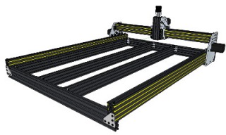
    UPDATE (12-1-14): I was going to build this machine geared toward milling aluminum plate. After much thought and discussion with some knowledgeable people here I have decided that it would be more trouble than it's worth to get this design to machine aluminum accurately enough for my needs. Therefore I have decided to scale back this design a bit and use it for cutting plastic and wood. It will still be "slightly beefier" than the original OX design but a lot less "beefier" than I was initially planning.

    In the mean time I will be designing and building another machine for my aluminum milling adventures. This machine will use Linear rails, Ballscrews, and beefier extrusions.


    Read more about this build...
     
    #1 Nugz, Nov 6, 2014
    Last edited: Dec 7, 2014
  2. Travis

    Travis New
    Builder

    Joined:
    Mar 27, 2014
    Messages:
    24
    Likes Received:
    12
    I'd like to add something, maybe it can help. I'v built an ox cnc, with 1/4" 6061 aluminum plate. The dimensions of the machine are 1500mm x 1000mm x 200mm. I'v also gone the route to over build mine as well. I'v been updating my machine for about a year now. I'v gone with the single rail of 1500mm for the long x axis, and this is sufficeint, if you add cross rails for side to side stiffness. I see you have rails the long way down, I did the same also, but then I did cross rails over those, all cut with a stop block while cross cutting to ensure the cross rails did not take the x axis out of parallel. Also for the 1000mm y axis, I went and tripled the rail, and bolted the 3 rails together. This created a wider rail which 3 solid v wheels span. The z axis for the ox build is a lost cause, I ended up buying SBR12mm Linear rails and fabricating a custom z axis. The reason I'm telling you this is because I see your reason for building is to mill aluminum plate. The reality is that it wont mill it. Not accurately because the forces of cutting aluminum cause too much deflection. If you look at a calculator like on cnc cookbook, using a 2 flute carbide endmill, with a .02" depth of cut (per pass), running 8000rpm, and milling to get a fine finish, which is about 7IPM. The cutting force in pounds is .82. Now that seems doable which it is slightly, but between the backlash that will occur on the delrin acme nut, and lateral flex on the y axis, it will still be difficult to mill aluminum, if you can at all. I'v experimented a lot, and finally came to point where I built the new z axis. Now I'v done some tests on my y axis also, and it can barely handle 1lb of lateral force on it with out flexing, and that is with a 3 wheel span. I will eventually be upgrading that also. I'm not writing any of this to discourage you, but it changes once you own a cnc, and have spent your time and money in the wrong way. I'm not saying openbuilds doesn't hae good stuff, because they do, and it's a great cnc, but it was not engineered to mill aluminum. I also would like to mention that I upgraded my pulleys to steel pulleys from mcmaster-carr, because I kept getting belt slippage from attempting to mill aluminum. The steel pulleys have deeper gear teeth, and deep belt teeth for a more positive grip. But I will still be upgrading my Y axis to SBR12 rails, like I did for the z axis. If you'd like to see pictures of my upgraded OX cnc router, I would be happy to post them for you. I'd like to also say one more time, that in no way am I downing Openbuilds, because I love the parts they have for great prices, My view point above is only in referance to milling aluminum.
     
    pmany and Nugz like this.
  3. Nugz

    Nugz New
    Builder

    Joined:
    Oct 8, 2014
    Messages:
    58
    Likes Received:
    10
    Travis,

    Wow! Thanks for the extensive reply! Your post confirmed many of my suspicions about my set-up. The more I have played with my model in Sketchup the more I keep thinking "still not strong enough to mill aluminum". At this point I'm invested only in the OX plates and some small odds-n-ends. There's two things I know a conventional milling machine can never have enough of, rigidity and density. The end goal being to reduce tool chatter as much as possible.

    I would love to see pictures of what you have done to upgrade your OX. And thank-you again for speaking up! You may have just saved me a bunch of money and time that would otherwise be wasted trying to "make" it work. The funny part is the timing. I just found some pre-built Z axis' yesterday on ebay that use linear rails and thought "now that’s what I should be using". I think my build is about to take on a whole new direction, so please do share your experience. Knowing what has and hasn’t worked for you will definitely save me time and money so I am very interested my friend.

    Thanks,
    -Nugz
     
  4. Travis

    Travis New
    Builder

    Joined:
    Mar 27, 2014
    Messages:
    24
    Likes Received:
    12
    Hey Nugz,

    This may seem like overkill, but I spent some time today putting together a rather long write up about my machine, a bit about cutting aluminum, and some stuff I would still change. Seeing your post here finally motiated me to share my experience, and I really hope it helps in some sort of way. I made a small blog for it because it was way to much to post here. So here is the link to my machine and all the info on. If you have any question about anything after, don't hesitate to ask, i'll help out the best I can. http://timberturn.weebly.com/
     
    pmany, GrayUK and Nugz like this.
  5. Nugz

    Nugz New
    Builder

    Joined:
    Oct 8, 2014
    Messages:
    58
    Likes Received:
    10
    Thanks Travis! I greatly appreciate it! I'm heading over to your blog to check it out.
    -Nugz
     
  6. Nugz

    Nugz New
    Builder

    Joined:
    Oct 8, 2014
    Messages:
    58
    Likes Received:
    10
    @Travis

    Hi Travis
    I'm assuming you used Nema 23 Motors? It says "24" on your blog. And I don't think you meant Nema 34. Just a heads up.

    I've been checking out Automation Technologies lately. I'm assuming that's Keling's new site? They have some great gear!

    Your Z-axis is more like what I had in mind for my build. It's very similar to the pre-built units I just found on ebay the other day. The one thing I would do differently, and the ebay ones don't have it, is to use a ball-screw for linear motion. The Chinese ball-screws look promising for what they cost. Do you have any experience with those?

    You and I must share a brain. I had the same idea about using a PC case as a dual purpose PC/Control Box. I build a lot of PC's so it naturally occurred to me to do this. Edit: Turns out this isn't such a great idea. I hadn’t given any thought to the "noise" generated between these components and the possibility of that noise causing interference. It is considered best practice to isolate the PC from the Driver components. I'm digging those Aviation Connectors. That's a great idea. Nice job on the cable sleeving. :thumbsup: I'm pretty handy with a soldering iron so that shouldn’t be a problem. Where is the best place to source those connectors?

    I did the same thing with my X-Axis (you call this axis your Y-Axis) in my model in Sketchup. I was going to "sister" (mechanically fasten) three 20x60 V-slot rails together and run a triple wheel set-up across the top and bottom using 12 of the newer Xtreme Solid V wheels from the part store. But after hearing about your experience with that set-up I am definitely rethinking my plan. That's $72.00 worth of wheels alone. Another idea was to use a Flitch Beam to stiffen up the X-axis. It has been talked about here before but for the uninitiated it simply means to sandwich two extruded aluminum rails around a steel flat bar and bolt them together. If I were to go that route I would just use steel V wheels across two steel rails, basically sandwiching two steel rails around a piece of extrusion. But then the whole point of the belt and pinion drive gets tossed out the window. :banghead: Speaking of the belt and pinion set-up. Can you provide some details about the steel pulleys and belting you used to modify your machine? I know you said you got them at Mcmaster-Carr but I'm not sure what you used that fits inside the V-slot rails. Do you have the part #'s for those by chance?

    I am definitely using a 220v VFD and 2.2 KW water cooled spindle for my machine. I also want to implement a flood coolant system or mister for cutting aluminum so I will be using an aluminum hold down table. This will add significant rigidity to my Y-axis (this must be what you call your X-Axis) as it will be fastened directly to the Y-axis frame. I know this still doesn’t compete with all of the cast iron in an actual milling machine but I figure it can't hurt either.

    Just a quick note on the axis' nomenclature that I use. I was taught that "Y" is toward/away, "X" is "across" (side to side), and "Z" is up/down when viewed from the front of the machine. This works best in my brain so I stick with it. I've noticed that some people here switch the Y and X for some reason and I find it confusing. :confused:

    We both had the same idea for strengthening the X-plate connection to the rear plate by using the existing extra holes to connect the two plates with long bolts and spacers. I even had Chris Laidlaw machine me a custom taller X-plate, based on Marks (kram242) design, so that I could add more bolts/spacers if needed.

    So, after reading your blog, I am left with the conclusion that I need to go with a redesigned Z axis using 2 supported linear rails and a Chinese ball-screw. I also need to re-design my X axis to either a Flitch Beam type with steel wheels riding on steel rails and a Chinese ball-screw for motion, or supported linear rails with a ball-screw. Either way the X-axis needs to be torsionally stiffer than what 3-20x60 rails alone can offer. That leaves the Y axis (long axis) with it's one true weakness being the belt drive. My thought there was to try a dual belt system with the bottom belt acting as rack (as in rack and pinion) as has been talked about here. With the belts facing each other so that their teeth engage each other across the length of of the axis and only separate at the pulley.

    Hmmm....lots to think about!

    Thank you so much Travis. I really appreciate the time and effort you have put into helping me out here. It's great to hear from someone who has already "been down that road." Please feel free to share any updates you have in the future. I would love to hear more about what you come up with. I went back and highlighted my questions for you if you get a chance to answer those I would appreciate it.

    Anyone else with suggestions please feel welcome to chime in! I'm always open to other thoughts and ideas.

    -Nugz
     
    #6 Nugz, Nov 28, 2014
    Last edited: Jan 3, 2015
  7. Travis

    Travis New
    Builder

    Joined:
    Mar 27, 2014
    Messages:
    24
    Likes Received:
    12
    Hey Nugz, yeah it's no problem and i'v totally been down that road :)

    Also yes I did mean nema 23, wasn't thinking, and here is a link to where I got the 4 axis kit - http://www.automationtechnologiesin...s/4-axis-nema23-cnc-kit-36v9-7a425oz-inkl4030

    It's pricey, but it's a quality kit I was pointed towards it by a friend who purchased his kit there as well.

    As for the chinese ball screws, ball screws are rated by a C scale, which basically just means how percisely they were made.
    All chinese ball screws are C7 grade screws, which is the lowest quality on the scale of ball screws. which equates to being the same as a precision acme screw. Everyone I know just ended up using precision acme screws, with anti backlash nuts. But as far as that goes, as long as the ball screw has a wear compensating nut it should be fine, after that it comes down to which is more cost friendly. So all in all the C7 ball screw is the same as having an acme screw.

    I actually originally got the aviation connectors from china on ebay, but after waiting 2-3 weeks with out them showing up, I ended up also buying those from automation technologies, purely because I had all my parts except for those, and wanted to get started. But if you search around I'm sure you can find them for a decent price.

    As for the x axis (shorter axis) the beam is super solid with the three 20x60 rails fastend together, the issue of the flex comes from the delrin solid v wheels. The beam itself is super solid when fastend together, and your idea with the steel v rail and the steel v wheels, is the right one, that is a much more rigid setup. CNC router parts website, uses steel V wheels one a cold rolled steel rail, Also check out Brian Oltragge - Grunblua CNC, he has a great cnc design, and it might give you some ideas as to your build. But yeah, I prob didnt make it clear enough in the overview I did of why the (x axis) had flex, but just wanted to specify one more time that it is purely the delrin wheel set-up, any other steel linear guidence would be the way to go.

    About the Pulleys, and the belt, the belt is slightly oversized in the rail, but here is the link to the steel pulley I used - http://www.mcmaster.com/#6495k718/=usuemc
    And here is the link to the matching belt - http://www.mcmaster.com/#7959k24/=usuffe
    Also I'm going to link you to the page where all the belting is, because they have an end plate there that might be useful for tensioning the belt, since the plate has the same tooth pattern as the belt - http://www.mcmaster.com/#catalog/120/1075/=usuf3n
    Just scrol down to the section - MXL, XL, L, H, and AT10 Series Belting and End Plates


    But yeah I know it is a ton to think about, I just know how much money I spent in the wrong way, and now I'm forced into a slow upgrade process. If I could do it all again, I would have gone with all steel and bearing linear motion. As for the belt drive, I haven't gotten my machine rigid enough to know if the belt and pulley system is as effective as lead screws or a real rack and pinion. But as it goes now, it's been fine other than not having a solid solution for keeping belt tension under heavy loads, which I feel if I had a good tensioning system, the belt would be completely fine.

    Also yeah it's a difficult decision to make, and it really comes down what your budget is. But the smartest way to go even tho this probably risks getting banned from the openbuilds site, is to redesign your machine for real linear motion, because the stuff here on a whole is to light wieght for the task of aluminum. It's meant to be an inexpensive way for people to enjoy having a cnc for light and soft materials.

    One more thing I'm on an IRC chat that's purely about cnc, I'll message you the network if your interested in talking to some of the guys on there, they are extremely knowledgable about everything cnc.
     
    Nugz likes this.
  8. Tweakie

    Tweakie OpenBuilds Team
    Moderator

    Joined:
    Jan 18, 2014
    Messages:
    784
    Likes Received:
    326
    No chance of being banned for expressing genuine and honest opinion. ;)

    Tweakie.
     
    Travis and Nugz like this.
  9. GrayUK

    GrayUK Openbuilds Team Elder
    Staff Member Moderator Builder

    Joined:
    May 5, 2014
    Messages:
    1,668
    Likes Received:
    627
    Haven't read ALL the above, but, don't you need 5 Steppers to make a 4 Axis CNC?
    2 x Steppers for Y.
    1 x Stepper for X.
    1 x Stepper for Z.
    1 x Stepper for A.
    Just being a bit of a Pedant here. :banghead:

    Or were they aiming it at a Threaded Rod Set-up Throughout, using the Fourth Stepper for Axis A.

    I think going heavier is probably the way to go. Cost is the main drawback for most of us. I've considered wider belts, with pinch wheels holding it into and against the Pinion wheel. That still seems feasible. :thumbsup:

    Good quality rods though are still a little rich for me. :cry:

    Bring in the "Mother Of Invention" here I think. Actually I think it is all about the "Mother Of Invention" element really. :rolleyes:

    Gray
     
  10. Nugz

    Nugz New
    Builder

    Joined:
    Oct 8, 2014
    Messages:
    58
    Likes Received:
    10
    @Travis

    Wow, again, thanks for all the info! I didn't know that about the C7 ball-screws vs. Precision lead-screws with anti-backlash nuts being considered roughly equal as a linear motion solution. That's good to know.

    However, something you said in your last post caught my attention: "As for the x axis (shorter axis) the beam is super solid with the three 20x60 rails fastened together, the issue of the flex comes from the delrin solid v wheels. The beam itself is super solid when fastened together, and your idea with the steel v rail and the steel v wheels, is the right one, that is a much more rigid set-up."

    That was my biggest concern. I must have misunderstood your original post. I thought you meant that the 60x60 (3-20x60 rails fastened together) X-axis still flexed under load. I didn’t realize that you meant that the flex was coming from the Delrin wheels.

    I know you built your OX as an early adopter but many of the issues you have mentioned have been worked out in the forum here in one way or another since then. There are many things you may have missed. So, before I totally give up on my current plan I have a few more questions for you:

    I intended to use all Polycarbonate Xtreme V wheels through-out my build as I was aware of the deflection with the original Delrin wheels. Have you tried the Polycarbonate Xtreme V wheels to see if they would eliminate the remaining flex in your Z-axis after your linear rail rebuild?

    Did you use the 5mm wide "GT3" belt (GT2 with a 3mm pitch) and the matching "GT3" (GT2 with a 3mm pitch) pulleys on your build originally, or was it the original 6mm wide GT2 2mm pitch parts? The "GT3" 3mm pitch stuff is supposed to be much better at preventing belt slip and at 5mm fits inside the V-slot track better.

    It may also be worth mentioning that I have a source for a TR8x8 Precision Lead-screw with matching anti-backlash Brass Drive nuts that I intended to use for my Z-axis. That should eliminate your concern about backlash with the Delrin nut from the part store...that's never in stock when I look anyway. :D I also have a modified taller X-plate with custom made 4-wheel aluminum spacer blocks.

    What I have been doing for several months now, is picking apart the OX design, looking for weaknesses, and thinking up ways to fix them without spending too much money or totally building from scratch. My end goal was to have the ability to do some light duty but accurate milling of aluminum plate for my own projects. Think of it as more of a prototyping scenario than a mass production one.

    So here is my current thinking:
    • I am confident in my Y-axis frame design, especially once the solid aluminum plate is bolted down to the extrusions to create the "table". This will tie all of the Y-axis rails together. There will be absolutely no chance of "racking". That's why I left out the cross-braces. I think this is the weakest link with your OX after the Delrin V wheels. My design is MUCH more rigid, you just cant see it in that crappy screen grab teaser pic I posted. :p
    • I am now confident in my X-axis solution of bolting three 20x60 V-slot's together as you have told me that yours is very rigid and is not the source of deflection at the tool tip.
    • I am fairly confident in the ability of the Polycarbonate Xtreme Solid V-Wheels to not deflect under load. They are much harder than the Delrin wheels I see in your pics. This is why they were added to the part store.
    • I am fairly confident in my stepper choice at 280oz/in. with a relatively flat torque curve.
    • I am very confident in my choice of spindle. (2.2kw/water cooled/ER20 collets with VFD)
    • I am fairly confident in the anti-backlash lead screw I have in mind.
    • I would be much more confident if I had a Z-axis like yours with the linear rail. I think this would greatly reduce the chance of deflection at the tool tip. I can source one if need be.
    • I'm stuck in the unfortunate situation of not having machine tools to build my machine with. If I had access to a large milling machine and a lathe I wouldn’t even bother with this approach.
    Thanks,
    -Nugz
     
  11. Travis

    Travis New
    Builder

    Joined:
    Mar 27, 2014
    Messages:
    24
    Likes Received:
    12
    I completely agree with you about not having certain tools to machine parts for the cnc. I also have to say, I'v seen the polcarbonate wheels, and I havent tried them. I may get some to see the difference in them compared to the delrin wheels.
    I do want to say tho, that it's easy to under estimate how rigid you linear motion needs to be for milling aluminum, I think the z axis absolutely needs to be steel rail construction. As for the x axis (shorter axis) I'm going to go ahead and order some of the polycarbonate wheels and replace them, to test how much rigidity it adds, lol I'v decided as I'm writing this post, and they will be cheaper for me since I already have all the bearings I need. As for the long axis, the way I have it now it's super rigid with no racking or flex, so if your going to put a plate down, that will be more than good enough. I also understand budget constraints, also the lack of tools. As far as the TR8*8 and the anti backlash nut, I'm sure that will be fine, because there is no load on the lead screw so it doesnt need to be a beast. Actually if you dont mind, it would be cool if you could post a link to where you found a brass anti backlash nut for the TR8*8. So all in all I'm going to order those polycarbonate wheels after I post this, and I can let you know what kind of difference it makes on that axis.
     
  12. Travis

    Travis New
    Builder

    Joined:
    Mar 27, 2014
    Messages:
    24
    Likes Received:
    12
    I also forgot to mention that, I did use both the GT3 belt and pulley.
    Also I did just order polycarbonte wheels to replace the delrin ones on the x axis (shorter axis)
    So they should be here sometime next week, and I'll let you know what the results are. :thumbsup:
     
    Nugz likes this.
  13. Nugz

    Nugz New
    Builder

    Joined:
    Oct 8, 2014
    Messages:
    58
    Likes Received:
    10
    Speaking of that...what is your Z travel now with the Linear Rail Setup?
    -Nugz
     
  14. Travis

    Travis New
    Builder

    Joined:
    Mar 27, 2014
    Messages:
    24
    Likes Received:
    12
    I ordered 200mm length rails which is about 7 7/8" long, I wanted a study stance on the pillow blocks, so it left me with about 3.5" of travel. Since I built up the bed of the cnc, I only hae about 3" of clearance for material thickness, so this length was more than enough for me.
     
  15. Nugz

    Nugz New
    Builder

    Joined:
    Oct 8, 2014
    Messages:
    58
    Likes Received:
    10
    It can't hurt right? Let me know how it works out.

    As far as the GT3 belt and pulley go, I wonder if your steppers are just too strong for the belt and pinion set-up? At 425oz/in. you are 250oz/in. over the OpenBuilds Nema 23's rated for 175oz/in.. I'd love to see what the belt-on-belt solution would do with your steppers. Another idea that came up here in the forums was a rack and pinion set-up, with the rack mounted in place of the belt in the V-slot channel (gear side facing up) with the stepper gears meshed directly to the rack.
     
  16. Travis

    Travis New
    Builder

    Joined:
    Mar 27, 2014
    Messages:
    24
    Likes Received:
    12
    Yeah, that's what I figured about the new wheels also, and worse case I can use the spare wheels for a ton of different things. As far as the rack and pinion or the dual belt belt thing I haent seen that, but would be interest in taking a look.
     
  17. Nugz

    Nugz New
    Builder

    Joined:
    Oct 8, 2014
    Messages:
    58
    Likes Received:
    10
    I'll see if I can dig up the thread where it was being discussed. It may be buried in the OX build thread somewhere, I can't remember where I read about it, but it was here somewhere. I do remember @The Dude was a big part of the discussion. I don't know if it ever went anywhere, as I've been a little sidetracked lately.
    -Nugz
     
  18. Nugz

    Nugz New
    Builder

    Joined:
    Oct 8, 2014
    Messages:
    58
    Likes Received:
    10
    #18 Nugz, Dec 2, 2014
    Last edited: Dec 2, 2014
  19. Nugz

    Nugz New
    Builder

    Joined:
    Oct 8, 2014
    Messages:
    58
    Likes Received:
    10
    Hi Gray,
    What are you on about mate? You answered your own question. I guess that's what a "Pendant" does though. :p I had to look up "Pendant" to understand what you were talking about. :confused:

    I agree. Going heavier to mill aluminum, or aluminium as you guys call it :D, is probably the best solution for me. I'm going to downsize my "Angus" build to a 750x1000mm machine and use it for acrylic, wood, and maybe some Garolite here and there. Its still going to be "slightly beefier" than the original Ox design, but I'm not going to go crazy with it.

    I'm going to build a leadscrew or ballscrew machine with linear rails for machining aluminum. I'm in the design process now. :thumbsup:
    -Nugz
     
  20. Travis

    Travis New
    Builder

    Joined:
    Mar 27, 2014
    Messages:
    24
    Likes Received:
    12
    Hey, just thought I'd update on how the polycarbonate v wheels worked out. I think it added a very slight difference on the flex of the x axis. But nothing to really get excited about :)
     
  21. Nugz

    Nugz New
    Builder

    Joined:
    Oct 8, 2014
    Messages:
    58
    Likes Received:
    10
    @Travis
    Thanks for the update Travis. Sorry it didn’t help much, I was hoping it would. It sounds like your X-axis deflection may be coming from elsewhere. Any thoughts? You have a much more substantial Z on your machine so we know that wouldn’t be the issue. If you apply force, by hand to the tool tip, is the deflection in the Y direction (front to back) or does it deflect in the X direction (side to side)?
    -Nugz
     
  22. Travis

    Travis New
    Builder

    Joined:
    Mar 27, 2014
    Messages:
    24
    Likes Received:
    12
    The deflection is in the Y direction front to back. I actually don't think that it's because the wheels arent hard enough or because they compress. I think it's because the wheel surface, and v groove is to slippery against one another. If the groove was deeper, or there was some way to have a more substantial interlock between the two it would be much more effective. But as for an easy fix, I'm not sure there is one. I think I just need a couple good linear rails, and redesign the drive system for that axis. Which may not be for a while since I dont have a need very often to mill aluminum, and I can do it very slowly if need be. But most of the time I use it for a lot of inlay work with wood.
     
  23. Nugz

    Nugz New
    Builder

    Joined:
    Oct 8, 2014
    Messages:
    58
    Likes Received:
    10
    @Travis
    I see. Inlay work huh? Cool. Whatcha' makin'? Got a website?
    -Nugz
     
  24. Travis

    Travis New
    Builder

    Joined:
    Mar 27, 2014
    Messages:
    24
    Likes Received:
    12
    :) no website, but as I'm getting slightly more seasoned with the cnc I may set one up, or a youtube channel showing some projects I do. The current project is an engagement ring box for my "hopefully" soon to be fiance. The box is being completely carved on the cnc, the box will be african mahogany with maple inlay. But my next project which will probably be my first youtube video, will be custom wooden handwheels for my tablesaw, since I broke one of the current handwheels. When I get started on it i'll post a link here. :)
     
  25. Rick 2.0

    Rick 2.0 OpenBuilds Team
    Staff Member Moderator Builder Resident Builder

    Joined:
    Dec 20, 2013
    Messages:
    2,892
    Likes Received:
    1,547
    Don't get too upset when she's more focused on what's in the box rather than the box itself. ;)
     
  26. Travis

    Travis New
    Builder

    Joined:
    Mar 27, 2014
    Messages:
    24
    Likes Received:
    12
    Lol rick, I won't mind at all :D
     
  27. Nugz

    Nugz New
    Builder

    Joined:
    Oct 8, 2014
    Messages:
    58
    Likes Received:
    10
    They are very distracted by shiny things aren’t they? :D

    @Travis
    Good luck with the engagement my friend. A guy who's willing to put that kind of work into asking for her hand should have no problem getting a "Yes" :thumbsup:
    -Nugz
     

Share This Page

  1. This site uses cookies to help personalise content, tailor your experience and to keep you logged in if you register.
    By continuing to use this site, you are consenting to our use of cookies.
    Dismiss Notice