Welcome to Our Community

Some features disabled for guests. Register Today.

Another Sphinx - 1000mm x 750mm

Discussion in 'CNC Mills/Routers' started by Nels, Jul 12, 2017.

  1. Nels

    Nels New
    Builder

    Joined:
    May 29, 2017
    Messages:
    33
    Likes Received:
    11
    Nels published a new build:

    Read more about this build...
     
  2. David Bunch

    David Bunch Veteran
    Builder

    Joined:
    Oct 27, 2014
    Messages:
    622
    Likes Received:
    427
    What format & where are the 50mm taller plates you mentioned? If they are in DXF format, you can use the free version of DraftSight to print to a PDF file or if you could give me the source of the DXF, sketchup or STL files I could probably create PDF files for you.
     
  3. Nels

    Nels New
    Builder

    Joined:
    May 29, 2017
    Messages:
    33
    Likes Received:
    11
    Thanks David, here are the sketchup files. I only need the PDF files for the two y axis sides plates, so I can glue them to the aluminium plate.
     

    Attached Files:

  4. David Bunch

    David Bunch Veteran
    Builder

    Joined:
    Oct 27, 2014
    Messages:
    622
    Likes Received:
    427
    See if this is what you wanted. I opened the sketchup file in TurboCAD & converted it to DWG, then opened & printed it to PDF from DraftSight. I printed the PDF files & the overall dimensions looked correct.
     

    Attached Files:

  5. Brian Popp

    Brian Popp Well-Known
    Builder

    Joined:
    Feb 27, 2017
    Messages:
    33
    Likes Received:
    57
    ****! Applaud you on the grit. That must have taken a while to cut/drill all those plates. Looking forward to seeing your build. By the way, if you find my build (Salmon Sphinx), I have a plate that moves the gantry up and back by 40mm. It's worked well for me gives you a bit more cutting area. Plans are attached.
     
  6. Nels

    Nels New
    Builder

    Joined:
    May 29, 2017
    Messages:
    33
    Likes Received:
    11
    Thanks David, that is exactly what I needed. Makes life a little bit easier for me.
     
  7. Nels

    Nels New
    Builder

    Joined:
    May 29, 2017
    Messages:
    33
    Likes Received:
    11
    Thanks for the info Brian.
     
  8. David Bunch

    David Bunch Veteran
    Builder

    Joined:
    Oct 27, 2014
    Messages:
    622
    Likes Received:
    427
    Only took a few minutes for me. Since you are cutting these by hand, thought I could help you out a little bit.
     
  9. whoflungdoo

    Builder

    Joined:
    May 24, 2017
    Messages:
    5
    Likes Received:
    0
    Hey guys, first post here. I'm also building this design. but making the plates by hand. Took a minute to figure out how to convert from step files to something I could print. The .dxf version comes up blank in my cad program. So I am using inkscape to import and then print. I have followed Brian's work on the salmon sphynx. and have started to make the plates. after today, I'm realizing I too would like to make it higher and further back. ? to Nels " what usable area will you get with the 1000x750 build?
     
  10. Nels

    Nels New
    Builder

    Joined:
    May 29, 2017
    Messages:
    33
    Likes Received:
    11
    I have not figured out the exact usable area.
     
  11. David Bunch

    David Bunch Veteran
    Builder

    Joined:
    Oct 27, 2014
    Messages:
    622
    Likes Received:
    427
    The dxf files I opened in DraftSight did not come into full view for me either. I zoomed extents to see the whole part.
     
  12. whoflungdoo

    Builder

    Joined:
    May 24, 2017
    Messages:
    5
    Likes Received:
    0
    David: I haven't used that program. but ,It's not a view problem on my end.....I did try that fix. didn't work. mine error's out saying "file contain nothing" then exits. but thank you for sharing that info.

    I've considered getting a newer cad program. might fix that problem. but a workaround will do and I'm just opening and printing as well.

    What I think happens is when saving the native file in whatever program your using or the builder is using. when you or they save the file as a dxf it has parameters and features that allow the drawing/mesh/object data to be stored differently in the dxf container file. my cad program is no longer supported, so it's probably looking in a default area of the file and seeing nothing ...so it errors.

    I do have a question though.....what is the formula for motor size on these (C-beam / Sphinx) builds. example. nema17 / 52oz. ex nema23 / 250oz. I have lots of spare nema 17's of various oz's but I see nema 23's used mostly and the plate's are setup for nema 23's....but whats the default formula? size in oz.
     
  13. Brian Popp

    Brian Popp Well-Known
    Builder

    Joined:
    Feb 27, 2017
    Messages:
    33
    Likes Received:
    57
    I used Nema 23 269 oz. You could probably go slightly smaller, but I don't think Nema 17's would cut it (so to speak).
     
  14. Kevon Ritter

    Kevon Ritter Veteran
    Builder

    Joined:
    Apr 30, 2015
    Messages:
    597
    Likes Received:
    292
    I also use 269oz. The required torque is more based on what you're cutting. I'm sure that ~80oz or even less will work perfectly fine cutting foam. A little more helps with moving the mass of the machine, but you're not really moving the machine as much compared to moving the endmill through your stock. As far as a formula? Too big is better than too small.
     
  15. David Bunch

    David Bunch Veteran
    Builder

    Joined:
    Oct 27, 2014
    Messages:
    622
    Likes Received:
    427
     
  16. Brian Popp

    Brian Popp Well-Known
    Builder

    Joined:
    Feb 27, 2017
    Messages:
    33
    Likes Received:
    57
    Yeah, and for leadscrew driven machines like the sphinx, you'll have resistance just from pushing the gantry around. For me at least, with multiple backlash nuts and 3/8" aluminum plates, this is significant. Agree that more is better, but also keep in mind that your drivers have to be able to handle the current. If you are using 8825 drivers on a GRBL board like me, that's around 2.5amps per axis, and larger motors won't give you any more torque.
     
  17. whoflungdoo

    Builder

    Joined:
    May 24, 2017
    Messages:
    5
    Likes Received:
    0
    lol....was going to ask about amp draw and controller selection.....but I think I have it figured out with all the help on the awesome site.

    I'm using a GRBL shield and Arudrino uno for the controller and external drivers. may switch as there's no parallel port...and I think you need that if your going to run mach3. was looking at the 3+ amp drivers.

    This isn't my thread but I hope the builder can use some of this info as well. And again thanks for all the help / advice.
     
  18. Nels

    Nels New
    Builder

    Joined:
    May 29, 2017
    Messages:
    33
    Likes Received:
    11
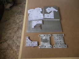
    Finished up 6 plates, except for the bearing cutouts. Y axis side plates next. Getting there slowly.
     

    Attached Files:

    Kyo likes this.
  19. whoflungdoo

    Builder

    Joined:
    May 24, 2017
    Messages:
    5
    Likes Received:
    0
    Hey,Looks Great....nice job!!

    I got everything printed over here...except the mod plates of .step design....Brian's Salmon Sphinx design... downloaded and installed Draftsight64. Installed in free mode. lots of failed attempts (AMD x2 chip)finally got it. now trying to get the .step files to open...looking at turbo cad now. I'm using Rhino Orig which blows on .step. a newer version prolly works fine.

    This all gives me flashbacks of ODB and all the different connectors....and now OBD2 with one. pressing on. cheers
     
    #19 whoflungdoo, Jul 16, 2017
    Last edited: Jul 26, 2017
  20. David Bunch

    David Bunch Veteran
    Builder

    Joined:
    Oct 27, 2014
    Messages:
    622
    Likes Received:
    427
  21. whoflungdoo

    Builder

    Joined:
    May 24, 2017
    Messages:
    5
    Likes Received:
    0
    Thanks David.

    Here's what I did..and it works.

    Freecad to open xxx.step then save as xxx.dxf (R12 old school).

    Got Draftsight working. big learning curve as background is black and lines are white. can't find color options. and I think the wizard interface is f*ck'n with me.

    Doesn't seem to be an import, So I've been using Open file and selecting the .dxf and printing from there...DraghSight doesn't like my printer configuration file. but I have fanagulled a print of each plate.

    Only thing left at this step is verification of prints , spacings and sizes.

    the only thing i've found so far is there's difference's in the spacing on the lead screw block (tighter/wider) of the salmon sphinx mod plates, not sure which way is right....more research on that needed.
     
  22. Brian Popp

    Brian Popp Well-Known
    Builder

    Joined:
    Feb 27, 2017
    Messages:
    33
    Likes Received:
    57
    I tried uploading some STL files, but it won't let me add them for some reason. Hit me up at bpopp (at) bpopp.net and I can get you a copy of the STL files.
     
  23. Poerdustin

    Builder

    Joined:
    Jun 22, 2017
    Messages:
    6
    Likes Received:
    0
    Looking good! Got me thinking about doing the plates by hand as well. Save some money. Do you have a pdf for the rest of the plates? I printed out the y-axis ones. What size bit did you use for the mini v wheels and solid v wheels? I assume the rest are 11/64. Also the bearing?
     
    #23 Poerdustin, Jul 19, 2017
    Last edited: Jul 19, 2017
  24. David Bunch

    David Bunch Veteran
    Builder

    Joined:
    Oct 27, 2014
    Messages:
    622
    Likes Received:
    427
    If you are looking for the PDF files of KYO's original C-beam Sphinx, he has them under the filename C-Beam CNC.zip in his build log:
    C-beam Sphinx

    I also have a question on where is the best place to buy this 1/4" size aluminum plate. I found this place which has a location near me & the price seems to be about $64 before shipping or tax for a 1/4"x31"x10" Aluminum Plate. That seems to be about the size needed with 10mm space around each part.
    Metal Supermarkets | Steel, Aluminum, Stainless, Hot-Rolled, Cold-Rolled, Alloy, Carbon, Galvanized, Brass, Bronze, Copper
     
  25. Poerdustin

    Builder

    Joined:
    Jun 22, 2017
    Messages:
    6
    Likes Received:
    0
    Thank you! I seen that but can not view those on my computer here at work. Unfortunately my son crashed my laptop and is being repaired and taking forever! Most of my research has been done on my phone which sucks! I was able to open the pdf files above though here at work. Guess i was hoping somebody had the rest of the plates like the files above. Once i get my laptop back i can use sketchup or fusion to view.

    Ive been looking at t6 6061 1/4" online and most prices ive seen for 10x36 has been $30-$40. Of course that doesnt include shipping. Think it said it weighs about 8.5 lbs.
     
  26. Nels

    Nels New
    Builder

    Joined:
    May 29, 2017
    Messages:
    33
    Likes Received:
    11
    I got my 1/4" aluminum plate on ebay. The size I got is 24" x 12", worked out great for the plates. I was going to get from Metal Supermarkets, but I am 120kms away from them. For a few dollars more it was better to get it mailed to me from Ebay.
     
  27. Nels

    Nels New
    Builder

    Joined:
    May 29, 2017
    Messages:
    33
    Likes Received:
    11
    Not sure what bit sizes I used, they were steal bits. For the countersink for the wheels I used a brad bit. I have not done the bearings yet, waiting for them to arrive in the mail. Thinking of using a 5/8" and 18mm brad bit for the bearings.
     
  28. Nels

    Nels New
    Builder

    Joined:
    May 29, 2017
    Messages:
    33
    Likes Received:
    11
    Here are the pdf template files that I used. These files were posted by Kyo.
     

    Attached Files:

    cmwwebfx likes this.
  29. Poerdustin

    Builder

    Joined:
    Jun 22, 2017
    Messages:
    6
    Likes Received:
    0
    Awesome!! Appreciate it..ill try these at work tommorrow. Should be fine.
     
  30. Nels

    Nels New
    Builder

    Joined:
    May 29, 2017
    Messages:
    33
    Likes Received:
    11
    Finished the Y axis side plates. All the plates are done now, except for the bearing inserts. Those will wait till my bearings come in.
     

    Attached Files:

    Kyo likes this.

Share This Page

  1. This site uses cookies to help personalise content, tailor your experience and to keep you logged in if you register.
    By continuing to use this site, you are consenting to our use of cookies.
    Dismiss Notice