Welcome to Our Community

Some features disabled for guests. Register Today.

Add more V-Slot to my Makerfarm 10" Prusa i3v

Discussion in '3D printers' started by David Bunch, Sep 30, 2019.
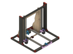
  1. David Bunch

    David Bunch Veteran
    Builder

    Joined:
    Oct 27, 2014
    Messages:
    622
    Likes Received:
    428
    I can't think of anything else to change, so will see if that stays true for the next few days. 8mm was the perfect amount to move it in as anymore inward was too close for the 1st nozzle outlet. I ran a simulation on the version just prior to the final & that is the image shown. I could not get the simulator to like the current version & I cannot see where a problem might be. I sometimes been using onshape.com to import the step file & create a parasoliid to troubleshoot problems, but that didn't help this time. The slicer has no problem with the STL file. The only thing I adjusted was shifting the outer bottom tube inward a little to give a little extra room.
    The horseshoe design I uploaded to thingiverse the other week is 34.61 cubic cm in volume. I have not made any changes to the horseshoe design since uploading that.
    This manifold design I uploaded was 46.53 & it is now down to 36.32 cubic cm. That is over 21% less volume. The actual airflow should be a little smoother at the junctions than shown in simulator as I chamfer or rounded those sharp edges. The simulator would not run with them shaved.
    TitanVertical_7run_ManifoldAirCoolerFlow_V7.jpg TitanVerticalOffset8mm_ManifoldAirCooler_V7.jpg
     
  2. David Bunch

    David Bunch Veteran
    Builder

    Joined:
    Oct 27, 2014
    Messages:
    622
    Likes Received:
    428
    I had a problem with the thingiverse page for the print cooler & could not resolve it, so I deleted it & uploaded it again under this: Titan Air Manifold Print Cooler by GeoDave . I also updated the previous posts that referred to the old page to point to the new page.
     
  3. JustinTime

    JustinTime Veteran
    Builder

    Joined:
    Dec 18, 2013
    Messages:
    756
    Likes Received:
    252
    Thanks, David, you da man!

    BTW, I missed the part where you use the shims. Where and why are they used?
     
  4. David Bunch

    David Bunch Veteran
    Builder

    Joined:
    Oct 27, 2014
    Messages:
    622
    Likes Received:
    428
    I thought this design came out quite well. The shims I used as a feeler gauge to set the height of the bottom of the print cooler above the bed. You can probably do this by eye, but thought 2-3mm was a good distance above the bed. With the bottom of cooler plate 2.3mm above the bed with nozzle touching bed, center of air flow should hit 4mm below the bottom of nozzle.

    Justin, I meant to ask, what kind of extruder configuration do you have.
     
    #64 David Bunch, Jun 7, 2020
    Last edited: Jun 7, 2020
  5. JustinTime

    JustinTime Veteran
    Builder

    Joined:
    Dec 18, 2013
    Messages:
    756
    Likes Received:
    252
    Right now I have the old style MK8 extruder like this one but I'm going to upgrade it soon the the one that Keith posted for the Vulcan, I think. Once I do the upgrade I will also install a long awaited cooling fan and your design is the victim. :D
     
  6. David Bunch

    David Bunch Veteran
    Builder

    Joined:
    Oct 27, 2014
    Messages:
    622
    Likes Received:
    428
    I finally changed this machine so none of the V-slot overlaps or extends out. Zyltech started selling different lengths of 2020 & 2040 of what they call V-Groove. 400mm is a good length for this machine on the X-axis extrusions. I could have also gotten away with using T-Slot for those 400mm lengths. I changed the front 2020 & middle bottom to 400mm (I used 2-2040x250mm scissored in for mid bottom before). The Top & back 2040 was changed to 400mm. The 2-2020's the X-carriage rides on were changed to 500mm. I also had to use a longer belt for the X-axis since I lengthened that. I have about 30-35mm extra space on the end of the X-axis, so 370mm lengths instead of 400mm would have also worked, but I would have had to cut those. I did end up having to cut a 2020 to 400mm length & used an old shower curtain draped over my miter saw to contain the aluminum shavings.

    IMG_9952_800x600.jpg IMG_9967_800x600.jpg
    One thing I did not allow for before starting this upgrade was the Z-axis End stop. Since I lowered the bed 20mm it was really close to getting the bed leveled. I had to temporarily add some plastic washer shims I had laying around. I have an assortment of those for just such an occasion.
    IMG_9957_800x600.jpg
    This allowed me to be able to print the replacement Z limit switch bracket. I made the Z limit switch T-nut connection to the middle of the vertical 2060 (Original design only had 2020 for the vertical). That gave me the space I needed. I added a couple of walls on the back of this bracket to press against the V-slot for a more solid connection & was a little tight getting the M2.5 nuts on there. A hemostat clamp worked really well for that as shown in 2nd photo below. I had to move that limit switch bracket lower than photo shows while leveling the bed.
    IMG_9959_800x600.jpg IMG_9960_800x600.jpg IMG_9964_800x600.jpg
    The back 2040x400mm is 3mm shy of being square at the back & I might change that by redoing the back Y-axis 2020s mounting bracket to shift the bottom back 3mm, but that does not really concern me since 3mm is hardly noticable. You can kind of see that 3mm gap in the picture with the 2 limit switch brackets. I do need to change that blue bottom angle bracket as before it was mounted to the V-slot & I added the V profile to it. Still works, but would be flush if I took that profile out of the design. I also have 300mm print height now. Original design I believe was about 250mm height & the version before this one was 280mm. On the previous iteration of this upgrade, the Z-axis seemed like it wanted to bind a little when raising it at several points. I must have fixed that while doing this upgrade, since it sounds nice all the way to 300mm. The only V-slot that is original on this machine now are the 4 2020x450mm lengths. 2 of those are on the Y-axis where the wheels roll against. The other 2 which used to be the Z-axis are the angle Back sides.

    This machine now has:
    2 - 2020x400mm
    4 - 2020x450mm
    4 - 2020x500mm
    2 -2040x400mm
    2-2060x500mm (2040 could have been used here)
     
  7. David Bunch

    David Bunch Veteran
    Builder

    Joined:
    Oct 27, 2014
    Messages:
    622
    Likes Received:
    428
    I have been wanting to change the wiring path from the extruder to the controller board for a while. I looked at using a drag chain, but there was not enough space between the M8 Lead Screw & the vertical 2060. Playing with some split tubing wire loom, I realized I could make holder to keep it in place on the extruder & the end of the V-Slot & seems to work similar to what a drag chain would do. I am going to rework the end holder as it bends a little close to the M8 lead screw, but looks ok for now. Adding some more structure between the bottom & top wire holder should fix it. I also made a hinged controller board case as I got tired of removing screws to get into the case to change something.

    I also moved the P/S to the same side as the controller board a few weeks ago to make the P/S wires shorter. I did that when I put my heat bed back on line with the heat bed mosfet. Since I also had to take the heat bed off to get to the wiring I had taped out of the way with kapton tape, I changed the 16 gauge heat bed wire to 14 gauge. I did not have any insulation under the heat bed & looked for some 12" cork squares as that is what I used before, but could not find what I wanted locally, so I did some google searching for heat bed insulation. I found some on Amazon, but then found the idea of using 1/8" thick by 2" pipe tape insulation in strips & it works well. The pipe tape was only $5 for 15 feet. I made 2 layers overlapping & only used 10 feet & that 12v 10" heat bed heats up to 45c quicker than the hotend. 60c-70c is probably as hot as I will need it to go. I have also had some squaring issues of the gantry. It was about 3mm higher on one side than the other, but I was printing reasonable well with it with the bed trammed to match it. While I had a lot of the machine apart, I pulled the gantry all the way out & started it level at the top & now it is less than 0.5mm off between sides. I still have a bit of wire mess on the side, but will attack that another day when it starts to bother me. Here are some progress photos.
    IMG_1101_800x600.jpg IMG_1105_800x600.jpg IMG_1106_800x600.jpg IMG_1107_800x600.jpg IMG_1079_800x600.jpg
     

Share This Page

  1. This site uses cookies to help personalise content, tailor your experience and to keep you logged in if you register.
    By continuing to use this site, you are consenting to our use of cookies.
    Dismiss Notice