Welcome to Our Community

Some features disabled for guests. Register Today.

A simple XY laser engraver/cutter

Discussion in 'Laser Cutters' started by HPB, Nov 2, 2016.
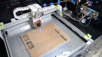
  1. HPB

    HPB Well-Known
    Builder

    Joined:
    Nov 28, 2015
    Messages:
    80
    Likes Received:
    52
    HPB published a new build:

    Read more about this build...
     
  2. Anthony Bolgar

    Anthony Bolgar Journeyman
    Builder

    Joined:
    Jan 14, 2016
    Messages:
    354
    Likes Received:
    198
    Nice little build.I am sure it will server you well. I would not bother changing it from a belt & pinion drive like you have, you would not see any real measurable difference for this application. Just keep the belts snugged up. DTR has a new diode now that pegs his power meter at 6.8W , but still has another amp of current at that level, so he figures it is closer to 8W, but will not advertise it higher than he can measure. And he has some cheap PWM laser drivers as well now. Since you are running GRBL, you should take a look at a great open source laser CAM software called LaserWeb (GitHub - openhardwarecoza/LaserWeb3: Open Source Laser Cutter / Engraver software. Supports gcode, svg, dxf, stl, png, jpg, bmp) It is very simple to use, is free, and outputs great quality raster engravings, as well as handling vector cutting great as well.
     
  3. HPB

    HPB Well-Known
    Builder

    Joined:
    Nov 28, 2015
    Messages:
    80
    Likes Received:
    52
    Thanks! Would the leadscrew mechanism improve any of the resolution? With this one I can't seem to go below 0.65mm pitch components. I have been looking for a laser CAM software. I'll be sure to give this a try. I didn't know DTR has inexpensive drivers as well. He has some pretty awesome lasers and is quite helpful too.
     
  4. Anthony Bolgar

    Anthony Bolgar Journeyman
    Builder

    Joined:
    Jan 14, 2016
    Messages:
    354
    Likes Received:
    198
    Leadscrew probably wouldn't improve resolution by much, try using the Prusa calculator (google it) and you can check different combinations to see the effect they have on resolution.
     
    #4 Anthony Bolgar, Nov 3, 2016
    Last edited: Nov 3, 2016
    HPB likes this.
  5. Keith Davis

    Keith Davis Veteran
    Builder

    Joined:
    Dec 11, 2013
    Messages:
    506
    Likes Received:
    393
    How powerful is this laser? Would it cut 1/8" acrylic sheet?
     
  6. Sungod3k

    Sungod3k New
    Builder

    Joined:
    Sep 26, 2016
    Messages:
    2
    Likes Received:
    1
    Hey, great build, what did you pay overall now for the whole machine?
     
  7. HPB

    HPB Well-Known
    Builder

    Joined:
    Nov 28, 2015
    Messages:
    80
    Likes Received:
    52
    The laser is about 1.6W. I have cut 3mm acrylic from this but with multiple passes. The tree design that is shown in the build was cut from a 2mm sheet with about 10 passes.
     
  8. HPB

    HPB Well-Known
    Builder

    Joined:
    Nov 28, 2015
    Messages:
    80
    Likes Received:
    52
    Thanks! I paid about $300 for the whole build including the laser. I also built a small enclosure to house the whole thing and that was extra but not by much.
     
  9. Keith Davis

    Keith Davis Veteran
    Builder

    Joined:
    Dec 11, 2013
    Messages:
    506
    Likes Received:
    393
    Excellent. I'm thinking of building one just to cut 216x316x3mm acrylic for build plates for 200x300 print beds for a 3d printer. Maybe later also side panels for a box type printer.

    Suggest a change on STL_Y_gantry. With two closed ends, the length of the X rail needs to be exact to prevent any binding on the Y wheels. Suggest closing only one side for the center anchor screw and leaving the other one open and placing a top hole for both for a screw to engage a slide tee nut in the X rail's top slot. That way final positioning on the open one's top screw would be done after the Y axis is assembled.

    [​IMG]
     
  10. HPB

    HPB Well-Known
    Builder

    Joined:
    Nov 28, 2015
    Messages:
    80
    Likes Received:
    52
    Yes you could do that but I don't see any purpose to that other than aligning the Y-axis extrusions edge-to-corner with the 2040 slots. The V-slot extrusions are sold in multiples of 500mm and I have not cut any to specific lengths and used only the standard sizes. If you look at the Fusion model too (see the image) the two Y-axis extrusions do not span the entire length of the 2040 rails. There is a small gap at one of the ends. This ensures that there is no additional pressure or bend on the plates and the wheels. I closed both the ends of the plates to ensure that the 2020 rail is firmly in place with both the Y-axis rails.

    316mm might be pushing it with just 500mm rails. I've managed to get a max laser-able area of 250mmx250mm without triggering the limit switches (soft limits). However the design is such that it can easily be expanded with larger rails.

    [​IMG]
     
  11. David the swarfer

    David the swarfer OpenBuilds Team
    Staff Member Moderator Builder Resident Builder

    Joined:
    Aug 6, 2013
    Messages:
    3,222
    Likes Received:
    1,813
    leadscrews will improve resolution, but vastly decrease speed. lasers like speed.
    You can calculate various things at GRBL settings calculator to see the effect of changes.
    You can get more resolution by:
    • use smaller pulleys to drive the belts
    • use more microsteps (less power and accuracy though, so increase current or voltage if this is a problem)
    Since you are running GRBL, do keep your eye open for the next release which is in beta now. v1.1 will give you a laser control mode that prevents burning in corners since the laser power is modulated in accordance with the acceleration..
     
  12. Keith Davis

    Keith Davis Veteran
    Builder

    Joined:
    Dec 11, 2013
    Messages:
    506
    Likes Received:
    393
    Or, 400 step motors instead of 200?
     
  13. Keith Davis

    Keith Davis Veteran
    Builder

    Joined:
    Dec 11, 2013
    Messages:
    506
    Likes Received:
    393
    Ah, yes. You're building from top to bottom, letting the Y axis wheels set the width of the Y rails. I was thinking of building from bottom up, where centering the X axis came last.

    You win! ;)
     
    HPB likes this.
  14. HPB

    HPB Well-Known
    Builder

    Joined:
    Nov 28, 2015
    Messages:
    80
    Likes Received:
    52
    This sounds awesome. I'll be sure to keep track of this. And thanks for the suggestions on improving resolution. Since my specific purpose was to cut stencils resolution is very important since the cutouts are really small.
     
  15. David the swarfer

    David the swarfer OpenBuilds Team
    Staff Member Moderator Builder Resident Builder

    Joined:
    Aug 6, 2013
    Messages:
    3,222
    Likes Received:
    1,813
    Then increasing mechanical resolution is more important than using more microsteps.
    So, smaller pulley (maybe with finer pitch belt?) , or even belt reduction of some kind.
     
  16. Anthony Bolgar

    Anthony Bolgar Journeyman
    Builder

    Joined:
    Jan 14, 2016
    Messages:
    354
    Likes Received:
    198
    IN your description you say not to use PLA. Why is that?
     
  17. evilc66

    evilc66 Journeyman
    Builder

    Joined:
    Jan 9, 2015
    Messages:
    392
    Likes Received:
    153
    Degradation from long term exposure to violet/blue light would be my guess.
     
    HPB likes this.
  18. Anthony Bolgar

    Anthony Bolgar Journeyman
    Builder

    Joined:
    Jan 14, 2016
    Messages:
    354
    Likes Received:
    198
    I have a ton of 20X40 extrusion. Is there any chance that someone could modify the 3d printed files to work with 20X40 instead of 20X20? I have no clue how to modify these files.
     
  19. HPB

    HPB Well-Known
    Builder

    Joined:
    Nov 28, 2015
    Messages:
    80
    Likes Received:
    52
    Got it! I'll read up more on this. Thanks.
     
  20. HPB

    HPB Well-Known
    Builder

    Joined:
    Nov 28, 2015
    Messages:
    80
    Likes Received:
    52
    PLA starts warping at temperatures as low as 40 deg C. It has mechanical rigidity but not the strength. The first version I had built was with PLA plastic and in just 6 months it started warping and cracking. Eventually it came apart.

    Attached here.
     

    Attached Files:

    #20 HPB, Nov 9, 2016
    Last edited: Nov 10, 2016
    GrayUK likes this.
  21. HPB

    HPB Well-Known
    Builder

    Joined:
    Nov 28, 2015
    Messages:
    80
    Likes Received:
    52
    Updated the endstops STL and deleted the existing one under Files. The old ones weren't wide enough to catch the limit switch levers.
     
  22. Anthony Bolgar

    Anthony Bolgar Journeyman
    Builder

    Joined:
    Jan 14, 2016
    Messages:
    354
    Likes Received:
    198
    Thank you for the file changes. Much appreciated. I rally need to learn how to do this myself, I just never seem to find the time to sit down and learn. ANy body have a good resource for a total beginner to learn from?
     
  23. HPB

    HPB Well-Known
    Builder

    Joined:
    Nov 28, 2015
    Messages:
    80
    Likes Received:
    52
    Yeah it seems daunting but when you really get to it, its quite simple. Youtube is a great starting point. I moved from Sketchup to Fusion 360 as there are a ton of things that F360 can do such as assembly and motion animation which are very tedious in Sketchup. Sketchup is great for folks just starting out with 3D modelling.
     
    Anthony Bolgar likes this.
  24. Anthony Bolgar

    Anthony Bolgar Journeyman
    Builder

    Joined:
    Jan 14, 2016
    Messages:
    354
    Likes Received:
    198
    Tried printing the cable clips and they are too large to fit into the extrusion.
     
  25. HPB

    HPB Well-Known
    Builder

    Joined:
    Nov 28, 2015
    Messages:
    80
    Likes Received:
    52
    Can you show a photo? Can they be fit in with some persuasion? The original clips I had were similar and had to be lightly hammered down. The current version has them sized exactly as the gap. If I could see a photo of how much larger they are I could post a resized version.
     
  26. Anthony Bolgar

    Anthony Bolgar Journeyman
    Builder

    Joined:
    Jan 14, 2016
    Messages:
    354
    Likes Received:
    198
    I will post a pic later today.
     
  27. Keith Davis

    Keith Davis Veteran
    Builder

    Joined:
    Dec 11, 2013
    Messages:
    506
    Likes Received:
    393
    I liked this fitting for use on a 3D printer. But I need it to fit with tension so it stays put. I moved the slot to the other side. I have to compress it with pliers to get it into the slot, but it stays where I position it.

    [​IMG]

    STL HERE
     
    HPB likes this.
  28. Anthony Bolgar

    Anthony Bolgar Journeyman
    Builder

    Joined:
    Jan 14, 2016
    Messages:
    354
    Likes Received:
    198
    Well I feel like a complete idiot. Never realized until I started to assemble the 20X40 extrusion version of this that the wheels used are the mini wheels. Go figure, I have 4 mini wheels and 42 regular size extreme V wheels. So time to order some more mini wheels. And another delay. But I need to wait for some GT2 belt and pulleys to arrive so hopefully the wheels will get here at about the same time. Did place an order with DTR laser shop for a 6.8W diode laser (Diode is actually closer to 8W, he does not have a meter that goes above 6.8, so he won't officially advertise them any higher) I already have one of his PWM drivers and a complete GRBL shield and motor setup so at least everything is now ordered, and will only take about a day to finish the build once everything gets here. In the mean time, I need to decide on final dimensions for the X and Y axis. I was thinking of making the X axis 500mm and the Y axis somewhere between 500mm and 750mm. Advice on build size gladly accepted, having trouble deciding.
     
  29. HPB

    HPB Well-Known
    Builder

    Joined:
    Nov 28, 2015
    Messages:
    80
    Likes Received:
    52
    Dimensions are really upto what you want to engrave/cut. Since these are extrusions, they are sturdy enough to not sag in the middle (depending on the weight of the X-motor mount with the 6.8W laser). 500mm should be good. I prefer not to cut the extrusions since I have to setup a whole circular saw jig for that and I'd rather just use the lengths I have.

    You might have to modify the X-axis mount to accommodate the 6.8W laser since that one is going to need some cooling.

    Were you able to figure out the Cable Clips? A slightly smaller version is attached here. There is also one on Thinigverse but I'm not sure it'll clear the motor mount screws.
     

    Attached Files:

  30. Anthony Bolgar

    Anthony Bolgar Journeyman
    Builder

    Joined:
    Jan 14, 2016
    Messages:
    354
    Likes Received:
    198
    I will give the smaller clips a try today. I am also going to try my hand at modifying the stls for use with the larger wheels, but then laser cut the modified mounts from 1/4" Acrylic, and see how that goes. Using the 20X40 extrusion, I do not think I need the 3D printed pockets on the Y plates., with 2 screws at each end it should not twist. I also want to make an X axis that would have a small Z slide for mounting a 300W spindle for PCB milling.
     

Share This Page

  1. This site uses cookies to help personalise content, tailor your experience and to keep you logged in if you register.
    By continuing to use this site, you are consenting to our use of cookies.
    Dismiss Notice