Welcome to Our Community

Some features disabled for guests. Register Today.

1075 Sphinx

Discussion in 'CNC Mills/Routers' started by NeeqOne, Jun 22, 2018.
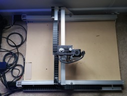
  1. NeeqOne

    NeeqOne Well-Known
    Builder

    Joined:
    Mar 3, 2018
    Messages:
    46
    Likes Received:
    27
    NeeqOne published a new build:

    Read more about this build...
     
  2. NeeqOne

    NeeqOne Well-Known
    Builder

    Joined:
    Mar 3, 2018
    Messages:
    46
    Likes Received:
    27
    As you can see from the build picture, there are cables everywhere. I want to get the machine running and use it to mill parts for my enclosure. Moreover, I want to sleeve all the cables with the exception of the one for the spindle.
     
  3. James_Hopkins

    Builder

    Joined:
    Jul 16, 2015
    Messages:
    28
    Likes Received:
    6
    I can't wait to see a video on it running. I wanna see how the belt drive X axis works.
     
  4. NeeqOne

    NeeqOne Well-Known
    Builder

    Joined:
    Mar 3, 2018
    Messages:
    46
    Likes Received:
    27
    I just sent G91 G0 X30 and G91 G0 Y30 and measured the distance travel in both direction and they were 30mm. I need to find a way to calibrate the z-axis.
     
  5. Rick 2.0

    Rick 2.0 OpenBuilds Team
    Staff Member Moderator Builder Resident Builder

    Joined:
    Dec 20, 2013
    Messages:
    2,852
    Likes Received:
    1,524
    It can easily be calibrated using a dial indicator or a set of calipers or even using a ruler set vertically against the face but if you're using the same screw on the z-axis as the others, it will have the same input value as the others.
     
  6. NeeqOne

    NeeqOne Well-Known
    Builder

    Joined:
    Mar 3, 2018
    Messages:
    46
    Likes Received:
    27
    First engraving test went well. Initially, the text was inverted. I had to change $3 in the configuration to fix it. I will play with the maker a couple of time before jumping to using bits.

    20180628_222151.jpg
     
    Michael.M and GrayUK like this.
  7. NeeqOne

    NeeqOne Well-Known
    Builder

    Joined:
    Mar 3, 2018
    Messages:
    46
    Likes Received:
    27
    I sleeved all the cables with the exception of the one for the spindle.

    20180701_174431.jpg

    20180701_174510.jpg
     
  8. NeeqOne

    NeeqOne Well-Known
    Builder

    Joined:
    Mar 3, 2018
    Messages:
    46
    Likes Received:
    27
    I have been able to get grbl to turn my spindle on and off. However, the spindle runs at the maximum rpm. Issuing the command S8000 has no effect on the speed at all. I will be glad if I can get some assistance to in setting up grbl to control the speed of the spindle. I am using bCNC. Moreover, I have attached the wiring diagram from my controller board (Phoenix) to the VFD below.

    VFD Wiring.png
     
  9. NeeqOne

    NeeqOne Well-Known
    Builder

    Joined:
    Mar 3, 2018
    Messages:
    46
    Likes Received:
    27
    I connected a 1K remote potentiometer, with the VFD 10v to one leg of the pot, VI to the Wiper Center leg and other leg to ACM. I was able to control the speed using the potentiometer with PD001 = 1 and PD002 = 1.

    However, once I hook up the VI and ACM to the phoenix CNC controller board, I am unable to control the spindle speed. It seems the VFD is not the problem. The problem might be the CNC controller or grbl settings. I will be glad if anyone can help with fix this issue.
     
  10. NeeqOne

    NeeqOne Well-Known
    Builder

    Joined:
    Mar 3, 2018
    Messages:
    46
    Likes Received:
    27
    Preparing to install T-tracks.

    20180713_195836.jpg
     
    Michael.M likes this.
  11. Michael.M

    Michael.M Veteran
    Staff Member Builder Resident Builder

    Joined:
    Jan 21, 2017
    Messages:
    432
    Likes Received:
    263
    Awesome wasteboard! I attempted to do the same thing but I damaged my t-tracks when trying to enlarge the screw holes. Mine were drilled for some strange size countersink screws that I didn't have.
     
  12. Michael.M

    Michael.M Veteran
    Staff Member Builder Resident Builder

    Joined:
    Jan 21, 2017
    Messages:
    432
    Likes Received:
    263
    I'm still trying to figure out a near perfect solution to work holding. Actually, if I would have done research begore I bought my cast tooling plate, I would have bought a cast aluminum t-slot plate. I see them on eBay but they're really spendy.
     
  13. Giarc

    Giarc OpenBuilds Team
    Staff Member Moderator Builder Resident Builder

    Joined:
    Jan 24, 2015
    Messages:
    2,892
    Likes Received:
    1,609
    I just did something similar. I put 8 48 inch t tracks 2.75 inches apart on my work surface. I too have been trying to come up with the "perfect" clamping solution. This should help.
     
    Michael.M likes this.
  14. NeeqOne

    NeeqOne Well-Known
    Builder

    Joined:
    Mar 3, 2018
    Messages:
    46
    Likes Received:
    27
    20180930_200156.jpg

    This is the current state of my CNC. I am using a spring loaded pen to test and calibrate the machine. Also, I am using ESTLCAM with an Arduino Uno since the spindle control does not work on the phoenix controller.
     
    GrayUK and Michael.M like this.
  15. Michael.M

    Michael.M Veteran
    Staff Member Builder Resident Builder

    Joined:
    Jan 21, 2017
    Messages:
    432
    Likes Received:
    263
    I remember you saying something about your Phoenix controller having issues. Do you like the arduino? Your test looks good dude! I bet you could test cut something. You should try cutting HDPE cutting boards with a single flute cutter. Literally zero effort for the machine.
     
  16. Michael.M

    Michael.M Veteran
    Staff Member Builder Resident Builder

    Joined:
    Jan 21, 2017
    Messages:
    432
    Likes Received:
    263
    Plus plastic tends to make little curly chips that are easy to clean.
     
  17. Michael.M

    Michael.M Veteran
    Staff Member Builder Resident Builder

    Joined:
    Jan 21, 2017
    Messages:
    432
    Likes Received:
    263
    Did you calibrate your steps per mm? Like tell the machine to move X axis so far and measure actual moved distance?
     
  18. NeeqOne

    NeeqOne Well-Known
    Builder

    Joined:
    Mar 3, 2018
    Messages:
    46
    Likes Received:
    27
    I have done that. But, I will do it once again. I bought a digital indicator to help with calibrate the whole CNC. I am putting together a dust collection system. These the items I am using.
    1. High Efficiency Dust Separator, 12 in. dia, with 2.5 in hose, 36 in. long
    2. 5 gal. Homer Bucket
    3. 12 Gal. 5.0-Peak HP Wet/Dry Vac with Tumbler
    4. Dust Shoe
    I have a shop vac but it is not as powerful as the one listed above. I hope to sell it and use the funds to purchase the 12 gal one.

    IMG-20180926-WA0003.jpeg

    The above is another drawing. Once I get the dust collection system in place, I will do some test cuts.
     
    Scotty Orr and GrayUK like this.
  19. NeeqOne

    NeeqOne Well-Known
    Builder

    Joined:
    Mar 3, 2018
    Messages:
    46
    Likes Received:
    27
    I decided to re-calibrate my X and Y axes and also optimize my ESTLCAM settings. Machine was able to draw this Mickey Mouse with no issue.

    20181005_182011.jpg


    [​IMG] 20181005_183401_1.gif
     
    Michael.M likes this.
  20. Michael.M

    Michael.M Veteran
    Staff Member Builder Resident Builder

    Joined:
    Jan 21, 2017
    Messages:
    432
    Likes Received:
    263
    That's pretty cool dude. I've never done anything like that but have wanted to try it. I think I've seen people use spring loaded pen holder devices for whatever reason although you seem to be doing fine with it chucked up.
     
  21. NeeqOne

    NeeqOne Well-Known
    Builder

    Joined:
    Mar 3, 2018
    Messages:
    46
    Likes Received:
    27
    my pen is spring loaded.
     
  22. Michael.M

    Michael.M Veteran
    Staff Member Builder Resident Builder

    Joined:
    Jan 21, 2017
    Messages:
    432
    Likes Received:
    263
    Oh nice
     
  23. Giarc

    Giarc OpenBuilds Team
    Staff Member Moderator Builder Resident Builder

    Joined:
    Jan 24, 2015
    Messages:
    2,892
    Likes Received:
    1,609
    Is it a purchased pen holder, or a 3D print with files available. Recently, I have been using one I printed from this this file, but it is not the best for drawing small circles. It is this one:[​IMG]
     
  24. Michael.M

    Michael.M Veteran
    Staff Member Builder Resident Builder

    Joined:
    Jan 21, 2017
    Messages:
    432
    Likes Received:
    263
    Oh ok. It truly looks like a short pen chucked directly in the collet from your GIF you uploaded.
     
  25. NeeqOne

    NeeqOne Well-Known
    Builder

    Joined:
    Mar 3, 2018
    Messages:
    46
    Likes Received:
    27
    I just cut a ballpoint pen into two and put the spring from the tip at the end.
     
    Rick 2.0 likes this.
  26. Giarc

    Giarc OpenBuilds Team
    Staff Member Moderator Builder Resident Builder

    Joined:
    Jan 24, 2015
    Messages:
    2,892
    Likes Received:
    1,609
    That is way to easy and brilliant. My problem is I stumble across things on thingiverse I really didn't know I needed until I saw one. That was how I ended up with an overly complicated pen mount. :thumbsup:
     
  27. NeeqOne

    NeeqOne Well-Known
    Builder

    Joined:
    Mar 3, 2018
    Messages:
    46
    Likes Received:
    27
    20181006_212508.jpg

    This is my simple solution. Once I get a 3d printer, I will go with a different solution. This has helped me to calibrate the feedrate and accelerate in ESTLCAM. My machine was skipping some steps during some drawing.
     
    Michael.M likes this.
  28. NeeqOne

    NeeqOne Well-Known
    Builder

    Joined:
    Mar 3, 2018
    Messages:
    46
    Likes Received:
    27
    I just finished my first mill on my CNC. In as much as everything went smooth, there is a slight issue with the part I milled.

    20181025_193959.jpg

    As indicated in the picture, the part marked is not vertically straight as the other parts. What could be the cause of this? The machine bed is not level yet. Could this be the issue? Thanks.
     
    Michael.M likes this.
  29. NeeqOne

    NeeqOne Well-Known
    Builder

    Joined:
    Mar 3, 2018
    Messages:
    46
    Likes Received:
    27
    I try surfacing a piece of MDF to test a new bit I bought. It seems some layers are slightly higher than others after surfacing. Any clue what the issue might be? Thanks

    20181101_134028.jpg
     
  30. GrayUK

    GrayUK Openbuilds Team Elder
    Staff Member Moderator Builder

    Joined:
    May 5, 2014
    Messages:
    1,668
    Likes Received:
    627
    I think, looking at your picture, you're going to need to do some "Tramming". i.e. Either your spindle, your X-axis, your Z-axis, or all three, are not square to the bed. You need to get out your best and most accurate squares and have a check.
     
    CNCMD and NeeqOne like this.

Share This Page

  1. This site uses cookies to help personalise content, tailor your experience and to keep you logged in if you register.
    By continuing to use this site, you are consenting to our use of cookies.
    Dismiss Notice