Welcome to Our Community

Some features disabled for guests. Register Today.

BlackBox

Discussion in 'Other Builds' started by Mark Carew, Feb 22, 2019.
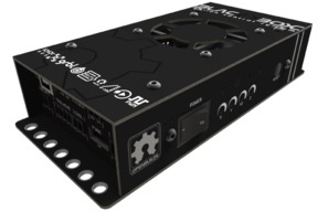
  1. Peter Van Der Walt

    Peter Van Der Walt OpenBuilds Team
    Staff Member Moderator Builder Resident Builder

    Joined:
    Mar 1, 2017
    Messages:
    14,047
    Likes Received:
    4,123
    Easier wiring, more reliable, warranty, 3.2A RMS drivers (Little drivers on a CNC shield top out at 1.5A RMS with cooling, little breakout PCBs are too small to effectively heatsink a driver)
    Refer to docs.openbuilds.com/blackbox
     
    Mark Carew likes this.
  2. DarkPenguin

    DarkPenguin Well-Known
    Builder

    Joined:
    Sep 16, 2017
    Messages:
    201
    Likes Received:
    65
    Clean, simple, supported solution. Connectors are tremendous. Ease of use is tops. I haven't fried a driver yet. I burned through a lot of bigfoot drivers in my last setup. That setup would fry a driver on just about any glitch. (At least until I put a blower fan directly on them.) BB doesn't seem to have that same issue.

    But if an arduino shield works for you then use that. No reason not to.
     
  3. laurent Besseas

    Builder

    Joined:
    Mar 26, 2020
    Messages:
    24
    Likes Received:
    1
    Thanks, just trying to understand as I'm new to CNC. Thanks
     
  4. ttodorov

    ttodorov New
    Builder

    Joined:
    Aug 8, 2014
    Messages:
    3
    Likes Received:
    1
    Hey everyone,

    I am trying to set up my BlackBox and am stuck on the spindle setup. I have an external PWM speed controller, so I connected the GND and PWM signals on the TOOLHEAD connector. So far no problem, I can measure the correct duty cycle with my oscilloscope.

    But I also want to use the internal relay to enable power to the external module. So I jumpered the relay for M3/M5 functionality. Unfortunately that works only with high duty cycle, something like S700 (using grbl defaults $30=1000 and $31=0). After investigating the grbl source and the BlackBox schematics, I figured out that the relay coil is driven by the PWM signal, when the jumper is set for spindle... (***? 5V relay coil to be controlled with a PWM signal with 5v@100% duty cycle !?! Thus makes the relay almost unusable in that configuration.)

    Is there any way to switch the relay to pin 17 of the MCU (PB5/D13_SP_DIR_OUT) and use grbl option USE_SPINDLE_DIR_AS_ENABLE_PIN? Without board surgery?
     
  5. David the swarfer

    David the swarfer OpenBuilds Team
    Staff Member Moderator Builder Resident Builder

    Joined:
    Aug 6, 2013
    Messages:
    3,288
    Likes Received:
    1,837
    surgery, or
    put the jumper on the other pin and use M8/M9 to turn on/off the relay, then modify the post to always output M8 with the M3 command and output an M9 with the M5 command.

    or create an arduino program that turns the slightest PWM signal into an on/off signal and use that instead of the onboard relay
     
  6. Peter Van Der Walt

    Peter Van Der Walt OpenBuilds Team
    Staff Member Moderator Builder Resident Builder

    Joined:
    Mar 1, 2017
    Messages:
    14,047
    Likes Received:
    4,123
    If you have one of the later revisions of the BlackBox there is a DIR/VFD jumper as well: Which version do you have? (We have v2.3 - v2.7 out in the wild)

    This ties Spindle Dir/Enable to the Relay (no surgery needed @David the swarfer) along with gnea/grbl - fully automatic Enable relay (originally added for VFDs needing a Relay between FOR/DCM to enable)

    IMG_1896.jpg

    Negative, if your use the relay as intended (OpenBuilds BlackBox 4X Documentation) you are not sending it PWM

    If its a version before the jumper was added, wire the relay to the Coolant output (M8/M9) and use that instead, just edit your post processors to include M8 in header and M9 in footer.
     
  7. ttodorov

    ttodorov New
    Builder

    Joined:
    Aug 8, 2014
    Messages:
    3
    Likes Received:
    1
    Absolutely perfect! Thank you very much for the VFD hint. Now it works as desired.
     
    Peter Van Der Walt likes this.
  8. microcvd

    microcvd New
    Builder

    Joined:
    Mar 19, 2020
    Messages:
    6
    Likes Received:
    1
    I just assembled a MiniMill and got it working with the PC GRBL software. Overall am very impressed with the build kit and instructions. We plan to use the MiniMill for a prototype laser material processing application.

    Some questions that are probably answered here already but here goes : Can you point me to resources on the Blackbox controller firmware? Is it open source to the point where I could control the G-Code execution in addition to having a way to program my other machine functions? Is it possible to add additional hardware I/O? I would want to interface it with Matlab and synchronize my laser processing with the MiniMill G-Code path execution.

    If I used another processor board for my Matlab interface what is easiest way to synchronize MiniMill execution? Ideally I want very tight control between laser power/duration and MiniMill path execution. The BlackBox almost has everything I need to control our material processing app but I need to add a few more capabilities.
     
  9. Peter Van Der Walt

    Peter Van Der Walt OpenBuilds Team
    Staff Member Moderator Builder Resident Builder

    Joined:
    Mar 1, 2017
    Messages:
    14,047
    Likes Received:
    4,123
    Standard Grbl gnea/grbl

    Negative with Grbl as-is.

    Matlab has Grbl plugins. Let that control Grbl and your other system, with Matlab handling the order of operations?
    Quick google, first result (so haven't worked with it myself): WJonson/MATLAB-GRBL-Controller
     
    #639 Peter Van Der Walt, Apr 24, 2020
    Last edited: Apr 24, 2020
  10. microcvd

    microcvd New
    Builder

    Joined:
    Mar 19, 2020
    Messages:
    6
    Likes Received:
    1
    Thanks Peter. In the future will use a different processor board to control the mill machine, talk to matlab, and handle instrumentation. Eventually would take the PC out of the loop to have real-time control.

    For our first-pass demo, is it possible to talk to the Blackbox through its auxillary serial interface and emulate the OpenBuilds Control app (same as Serial Console in OpenBuilds Control app)? Is GRBL the command set for that or is there an OpenBuilds command language? Just looking for simplest way to trigger a path sequence and return a "done" signal.
     
  11. Peter Van Der Walt

    Peter Van Der Walt OpenBuilds Team
    Staff Member Moderator Builder Resident Builder

    Joined:
    Mar 1, 2017
    Messages:
    14,047
    Likes Received:
    4,123
    Very simple, all explained here gnea/grbl

    Which version of the board do you have? v2.6 and older, or v2.7?
     
  12. microcvd

    microcvd New
    Builder

    Joined:
    Mar 19, 2020
    Messages:
    6
    Likes Received:
    1
    OK I will review GRBL link, thanks. Cannot tell which version board I have from order or shipping info. We bought it a month ago. PC console says VER:1.1g.20181112:MINIMILL
     
  13. Peter Van Der Walt

    Peter Van Der Walt OpenBuilds Team
    Staff Member Moderator Builder Resident Builder

    Joined:
    Mar 1, 2017
    Messages:
    14,047
    Likes Received:
    4,123
    Its printed in Silver on the boards themselves (take top cover off) - looking for v2.5, v2.6 or v2.7. If its not a V2.7, let me know - theres a couple tips for using AUX1
     
  14. microcvd

    microcvd New
    Builder

    Joined:
    Mar 19, 2020
    Messages:
    6
    Likes Received:
    1
    Found it, it's version 2.6.

    Also reviewed the GRBL interface doc and understand it. I have done a lot of work back in the day with serial monitors and interpreters so this will not be difficult for me.
     
    Peter Van Der Walt likes this.
  15. Funi

    Funi New
    Builder

    Joined:
    Mar 1, 2016
    Messages:
    15
    Likes Received:
    6
    What are the A3 and A4 jumpers on v2.7 in the motor slave jumper set? upload_2020-4-28_15-49-18.png
     
  16. Peter Van Der Walt

    Peter Van Der Walt OpenBuilds Team
    Staff Member Moderator Builder Resident Builder

    Joined:
    Mar 1, 2017
    Messages:
    14,047
    Likes Received:
    4,123
    Funi likes this.
  17. Funi

    Funi New
    Builder

    Joined:
    Mar 1, 2016
    Messages:
    15
    Likes Received:
    6
    Somehow didn't read well enough to understand that the Blackbox didn't support 4th axis and bought this as an "upgrade" to my 4 axis machine. Saw the A pins and was hoping this was hinting at a future A axis addition but I guess I'm out of luck.

    I see on the GRBL page it hints at a future possibility of 4 axis, but with the BlackBox processor, that is probably not going to happen?

    I thought OpenBuilds had a 4 axis controller in the store, surprised to see that's no longer an option and guess I read what I wanted to read on this one.
     
  18. Peter Van Der Walt

    Peter Van Der Walt OpenBuilds Team
    Staff Member Moderator Builder Resident Builder

    Joined:
    Mar 1, 2017
    Messages:
    14,047
    Likes Received:
    4,123
    We'll all see someday when Gnea (Grbl successor) is released. Until then, plans, rumours and hopes.


    You can still source those directly from PlanetCNC https://planet-cnc.com
     
  19. Grif

    Grif New
    Builder

    Joined:
    Feb 27, 2017
    Messages:
    8
    Likes Received:
    0
    Im looking at wiring diagram for nema 23 motors that state from data sheet that green=A Yellow A- Red=B and Blue=B-. So why does black box list Red=A Blue=A- green=B yellow=B-. Im hope this is just a typo on the device or am I reading it wrong?
     
  20. Funi

    Funi New
    Builder

    Joined:
    Mar 1, 2016
    Messages:
    15
    Likes Received:
    6
    After browsing around on here I found comments about the "next version of grbl will support 4th axis" going back to 2013. :(

    Really love the Blackbox but need that extra axis. Design and build of it are awesome, and the interface looks clean.
     
    Peter Van Der Walt likes this.
  21. Funi

    Funi New
    Builder

    Joined:
    Mar 1, 2016
    Messages:
    15
    Likes Received:
    6
    The pairs are whats important, so while they should be consistent in each wiring diagram, it sounds like both are correct.
     
    Peter Van Der Walt likes this.
  22. Peter Van Der Walt

    Peter Van Der Walt OpenBuilds Team
    Staff Member Moderator Builder Resident Builder

    Joined:
    Mar 1, 2017
    Messages:
    14,047
    Likes Received:
    4,123
    So in both, RED+BLUE = a pair of wires belonging to the same coil
    and YELLOW+GREEN = a pair of wires belonging to the (other) coil
    Thats fine, the order is largely irrelevant, all that matters is identifying the pairs. So, BOTH are correct :)
     
    #652 Peter Van Der Walt, Apr 30, 2020
    Last edited: Apr 30, 2020
    Alex Chambers likes this.
  23. Peter Van Der Walt

    Peter Van Der Walt OpenBuilds Team
    Staff Member Moderator Builder Resident Builder

    Joined:
    Mar 1, 2017
    Messages:
    14,047
    Likes Received:
    4,123
    I think [email protected] is already working on you in regards to that right?
     
  24. Funi

    Funi New
    Builder

    Joined:
    Mar 1, 2016
    Messages:
    15
    Likes Received:
    6
    Yeah I'm good, just wanted to say on here that it's a cool design.
     
  25. Peter Van Der Walt

    Peter Van Der Walt OpenBuilds Team
    Staff Member Moderator Builder Resident Builder

    Joined:
    Mar 1, 2017
    Messages:
    14,047
    Likes Received:
    4,123
    Appreciate the feedback, just wanted to make sure you are happy first! :)

    Hey, next machine then! (;
     
  26. Pyrotechnic

    Builder

    Joined:
    Jan 31, 2018
    Messages:
    2
    Likes Received:
    0
    Hi,

    I've finally gotten around to building my Black Box (fantastic build!) and plugging some power and servos (NEMA 23s) in. I've noticed that the servos are drawing current when not being driven. With just power and USB plugged in, the BB is drawing 82mA, 164mA with 1 servo plugged in, 242mA with 2 servos, 324mA with 3 and 410mA with all 4. I can also hear a very faint hum/hiss coming from the servos. Is this right? This current draw doesn't change if I adjust the adjustment screws on the side (didn't expect it to).

    Apart from that I can drive them all CW and CCW just fine as far as I can tell. That's about as far as I've gotten so far. Looking forward to getting everything bolted together!

    edit: It's a v2.5 board
     
    #656 Pyrotechnic, May 2, 2020
    Last edited: May 2, 2020
  27. Alex Chambers

    Alex Chambers Master
    Moderator Builder

    Joined:
    Nov 1, 2018
    Messages:
    2,700
    Likes Received:
    1,327
    Depends on your grbl settings, if you have $1=255 the motors will be powered when idle.
    Alex.
     
    Pyrotechnic likes this.
  28. Pyrotechnic

    Builder

    Joined:
    Jan 31, 2018
    Messages:
    2
    Likes Received:
    0
    And had I bothered to read past the 1st sentence of that tool-tip I'd know that...

    Much appreciated, thank you!
     
  29. SeanD

    SeanD Well-Known
    Builder

    Joined:
    Mar 23, 2019
    Messages:
    207
    Likes Received:
    65
    Is it possible to hook up a power relay switch to the coolant connections to turn power on and off to a coolant pump? I have a pump that plugs into an Australian wall socket. Want to know what to ask an electrician to make for me and what command I need to send to the Blackbox to switch it on and off. Thanks in advance.
     
  30. Batcrave

    Batcrave Journeyman
    Builder

    Joined:
    Apr 20, 2018
    Messages:
    361
    Likes Received:
    165
    If I'm reading this right (which, based on recent history, is unlikely), then yes. It actually sounds suspiciously like exactly the setup the COOL output was named for. If not, then hopefully Peter or Rob or someone will jump in with a better answer before I can cause too much property damage.

    On my machine I'm using the COOL output wired to an IOT Relay with a shopvac plugged into it, which - (substituting the word "pump" for "shopvac") could avoid the electrician altogether. After that, all it ends up taking is an M8 / M9 in G-code to turn it on / off respectively.

    The only trick in that case would be either finding an AU-US adapter for the pump to plug into the IOTRelay and an IEC C13 to AU wall cord (both of which I assume should be easily available), or else - better but more challenging - hunt down an equivalent of the IOT Relay with local receptacles.

    If the IOT Relay isn't an option for whatever reason (whether technical or outrageous shipping costs) then, yes, it should be possible to put together (or have your electrician) put together a comparable relay from scratch... but if I try giving advice about the details it's likely to get someone killed.


    -Bats
    (strangled, most likely. or maybe shot. possibly even electrocuted, I suppose)
     
    SeanD likes this.

Share This Page

  1. This site uses cookies to help personalise content, tailor your experience and to keep you logged in if you register.
    By continuing to use this site, you are consenting to our use of cookies.
    Dismiss Notice