Welcome to Our Community

Some features disabled for guests. Register Today.

LEAD Lathe

Discussion in 'CNC Lathes' started by Giarc, Jun 14, 2020.
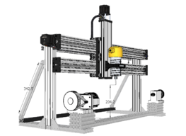
  1. Giarc

    Giarc OpenBuilds Team
    Staff Member Moderator Builder Resident Builder

    Joined:
    Jan 24, 2015
    Messages:
    2,969
    Likes Received:
    1,651
    No problem. I hope the settings work for you.
     
  2. Stairguy

    Stairguy New
    Builder

    Joined:
    Mar 3, 2023
    Messages:
    3
    Likes Received:
    0
    Is there any chance someone has worked up a fusion360 post for this set up? Y as the spindle, X and Z used for linear motion, and a black box controller.
    I mounted a trim router on Cbeam rails and have been making cylindrical objects using just the x and z axis. But now I have a stepper motor with gear reduction to drive the spindle. But I can’t seem to get a post to work. Any help is appreciated
     
  3. JustinTime

    JustinTime Veteran
    Builder

    Joined:
    Dec 18, 2013
    Messages:
    767
    Likes Received:
    254
    If you have easy access to the stepper motors plugs/connections just switch the Y and the Z and you're free to go.
     
  4. Giarc

    Giarc OpenBuilds Team
    Staff Member Moderator Builder Resident Builder

    Joined:
    Jan 24, 2015
    Messages:
    2,969
    Likes Received:
    1,651
    I have never attempted to use Fusion 360, because I already had Vectric Vcarve Desktop. So, I can design in Fusion, then export the item as an .stl file and import it into Vcarve to easily create the toolpaths. Can you do rotary on Fusion 360 without paying for the subscription? I tought that was only in the subscription, but I may be wrong.
     
  5. Giarc

    Giarc OpenBuilds Team
    Staff Member Moderator Builder Resident Builder

    Joined:
    Jan 24, 2015
    Messages:
    2,969
    Likes Received:
    1,651
    This video may be of assistance. I would assume that the normal OpenBuilds post should work since it is still just XYZ moves, but I have not personally tried it.
     
  6. Stairguy

    Stairguy New
    Builder

    Joined:
    Mar 3, 2023
    Messages:
    3
    Likes Received:
    0
    You are correct, but even with the subscription you need the additional machining extension for rotary paths, another cost...... 5 axis positioning with 3 axis toolpaths can be done with the free version now though.
    You mentioned an "OpenBuilds post" all I have tried is the autodesk Grbl post. Is there a place to download a better post?
    I get an error saying the post needs to be modified to allow 5 axis movement when i try the autodesk post
     
  7. Alex Chambers

    Alex Chambers Master
    Moderator Builder

    Joined:
    Nov 1, 2018
    Messages:
    2,730
    Likes Received:
    1,332
    Giarc likes this.
  8. Stairguy

    Stairguy New
    Builder

    Joined:
    Mar 3, 2023
    Messages:
    3
    Likes Received:
    0
    I tried the openbuilds posts, an error message about grbl being only 3 axis is the result.
     
  9. Tahir@NY

    Tahir@NY New
    Builder

    Joined:
    Jan 24, 2024
    Messages:
    14
    Likes Received:
    3
    Hello,

    I stumble upon this very helpful post of yours. On my machine, I have a rotoray attached to my X axis and I am going Along Y Axis (due to the table design). The openbuild $100 setting for me is 26.7 and it does a perfect 360 mm rotation. However, when I design my document in vcarve the diameter lets say 32 mm and length is 120 mm, the tool path it generates, never rotates around the stock, only 32 mm actual rotation (I used a blue tape to measure). I hope it make sense? If I set a diamter of 360 and generate toolpath, it then rotates one 1 full rotation. Wondering what am I doing wrong here. and my PP for the vcarve is GRBL MM Thank you
     
    #69 Tahir@NY, Jan 24, 2024
    Last edited: Jan 24, 2024
  10. Giarc

    Giarc OpenBuilds Team
    Staff Member Moderator Builder Resident Builder

    Joined:
    Jan 24, 2015
    Messages:
    2,969
    Likes Received:
    1,651
  11. Tahir@NY

    Tahir@NY New
    Builder

    Joined:
    Jan 24, 2024
    Messages:
    14
    Likes Received:
    3
    Thank you so much for your quick and informative reply. Upon reading the document, the process assumes that the setup is ALONG X and wrapping Y, In my case its ALONG Y and wrapping X. Would it still work? or do I have to modify it. Thank you again for your help.
     
  12. Giarc

    Giarc OpenBuilds Team
    Staff Member Moderator Builder Resident Builder

    Joined:
    Jan 24, 2015
    Messages:
    2,969
    Likes Received:
    1,651
    I do not know and I am not near my computer to look at the post processor. I would not be able to look for several hours
     
  13. Tahir@NY

    Tahir@NY New
    Builder

    Joined:
    Jan 24, 2024
    Messages:
    14
    Likes Received:
    3
    Thank you again for the quick reply. I figured it out with your help. I modified the processor based on my layout. Now it works as expected. Thank you for pointing me in the right direction.
     
    Rick 2.0 likes this.
  14. Giarc

    Giarc OpenBuilds Team
    Staff Member Moderator Builder Resident Builder

    Joined:
    Jan 24, 2015
    Messages:
    2,969
    Likes Received:
    1,651
    You are welcome. I am glad you got it working.
     
  15. Travisd

    Travisd New
    Builder

    Joined:
    Nov 13, 2023
    Messages:
    12
    Likes Received:
    0


    What did you use for software and what did you use for a post processor to get your code to make grout?
     
  16. Peter Van Der Walt

    Peter Van Der Walt OpenBuilds Team
    Staff Member Moderator Builder Resident Builder

    Joined:
    Mar 1, 2017
    Messages:
    14,428
    Likes Received:
    4,197
    Review the complete thread, there are in depth discussions on Vectric workflow, Post, Calibration etc. Its already in this thread, just start at page 1 onward
     
    Alex Chambers likes this.
  17. Giarc

    Giarc OpenBuilds Team
    Staff Member Moderator Builder Resident Builder

    Joined:
    Jan 24, 2015
    Messages:
    2,969
    Likes Received:
    1,651
    Vectric rotary post processor for grbl based machines. It is the Rotary Demon post processor: LEAD Lathe

    Here is a step by step on how to use it in Vcarve: LEAD Lathe
     
  18. Giarc

    Giarc OpenBuilds Team
    Staff Member Moderator Builder Resident Builder

    Joined:
    Jan 24, 2015
    Messages:
    2,969
    Likes Received:
    1,651
    Oh boy, that could take a bit. I believe I started a hand written one. I will have to look for it. It is basically a High Z Mod for Lead 1010 CNC which gets you the uprights of 500 mm 2080 and the new Z axis beam and lead screw. However, since it is meant to be an add-on to a LEAD 1010, it is expected you would reuse the plates, fastening screws, nut blocks, etc from the original Z axis.

    So, it may be useful to buy everything from a version of the C-Beam® XLarge Linear Actuator Bundle except the lead screw. You could then use that cbeam for the slide for the Tailstock. You would also need an additional 1000mm C-Beam® XLarge Linear Actuator Bundle for the second X axis member.

    Then, for the two "feet", you would need two 500mm pieces (Or 1 - 1000mm that you cut) V-Slot® 20x80 Linear Rail Technically, it could be probably be 2060, but I used 2080 because I had it already.

    You need a 1000mm piece of V-Slot® 20x20 Linear Rail and 4 Adjustable V-Slot Hinge for the side braces.

    At least 16: Cast Corner Bracket and they get fastened to the cbeam with 8mm screws so 32 of them. I sand the little nubs off the cast corner brackets for the part that does not go into the vslot. If you do not do this then you would need 16 - 10mm and 16 - 8mm screws. This occurs where they cross the slot perpendicular vs. lining up with it. I used the Drop In Tee Nuts Pack for fastening these because, in my opinion they are easier/less frustrating to use. SO you need at least 16. I would get a 50 pack just in case. I also used cast corner brackets to fasten the 2080 "feet" to the machine bed. but there are probably other ways.

    For the tail stock, I used the Tee Nuts - M5 Pack because they slide nice and easy in the Vslot when adjusting the tail stock.

    I also used 4 of these for bracing the uprights 90 Degree Joining Plate but unless you wanted to make custom plates like I did for the top of the upper Cbeam, then get 2 more. they take 5 each of the 10mm Low Profile Screws M5 (10 Pack).

    Again, I made a couple of custom plates for the back braces. I believe tis is because the off the shelf were too small so the hole positions would not work. Those were made from 1/4 ich so they took 12mm. But, unless you did the same, there is no need for those screws. I also do not really think the plates are necessary, but I wanted to be sure it was well braced.
    [​IMG]
    I will have to physically go look at it when I get a chance to see what I missed. Also, I forgot to mention I used a Black Box 4X which is no longer made. But this is better: BlackBox Motion Control System X32 and I used this 24V Meanwell Power Supply Bundle .and two of these: NEMA 23 Stepper Motor - High Torque Series

    If you want the custom plates I made, the files are uploaded in dxf format.

    -Craig
     
  19. Peter Van Der Walt

    Peter Van Der Walt OpenBuilds Team
    Staff Member Moderator Builder Resident Builder

    Joined:
    Mar 1, 2017
    Messages:
    14,428
    Likes Received:
    4,197
    Tag us on Instagram, Facebook or post about it here on the forum, we always love seeing projects
     
  20. Rick 2.0

    Rick 2.0 OpenBuilds Team
    Staff Member Moderator Builder Resident Builder

    Joined:
    Dec 20, 2013
    Messages:
    2,882
    Likes Received:
    1,539
  21. Giarc

    Giarc OpenBuilds Team
    Staff Member Moderator Builder Resident Builder

    Joined:
    Jan 24, 2015
    Messages:
    2,969
    Likes Received:
    1,651
    My linear actuator kit was 1000mm. It came with the lead screw and anti-backlash nuts and all other necessary components for motion. The High Z mod does NOT come with the 1000mm long screw because it is assumed you have one with the existing X axis on a Lead 1010 machine. I hope that makes sense. That is why I bought both. If you need 1500meter long stuff, then you may need to do a special request with the store and get the tensioning version.

    Can't wait to see the projects.
     
  22. Giarc

    Giarc OpenBuilds Team
    Staff Member Moderator Builder Resident Builder

    Joined:
    Jan 24, 2015
    Messages:
    2,969
    Likes Received:
    1,651
    I believe it will be helpful. Thanks.
     
  23. Peter Van Der Walt

    Peter Van Der Walt OpenBuilds Team
    Staff Member Moderator Builder Resident Builder

    Joined:
    Mar 1, 2017
    Messages:
    14,428
    Likes Received:
    4,197
    8mm Metric Acme Lead Screw (1040mm for a 1000mm actuator)
     
    Giarc likes this.
  24. Giarc

    Giarc OpenBuilds Team
    Staff Member Moderator Builder Resident Builder

    Joined:
    Jan 24, 2015
    Messages:
    2,969
    Likes Received:
    1,651
    The cbeams linear axis kit comes with the necessary lead screw for the x axis. The high z comes with the necessary 540 mm lead screw for z.
     
  25. Giarc

    Giarc OpenBuilds Team
    Staff Member Moderator Builder Resident Builder

    Joined:
    Jan 24, 2015
    Messages:
    2,969
    Likes Received:
    1,651
    @DrDarin I went out and took some pictures of the parts to determine what number and length of screws I used.

    4 angle brackets for each base of uprights and 8 8mm m5 screws and 8 t nuts for each side. If you choose not to sand off the little nubs on the brackets where they do not fit into the slots then you may need to substitute 10mm screws. The sand off real easy on a disk sander. see below
    1000001688.jpg
    I had some aluminum left over from another project so I cut mine out of 6.35 mm, but if you use these 90 Degree Joining Plate, there are two for each upright (4 total for uprights) and would require 8 mm M5 screws an t nuts. 20 of each total, ten per upright. see below
    1000001689.jpg

    Your Cbeam linear actuator comes with the necessary aluminum plates like these. However, I had some scrap 3/8" ABS plastic and cut two out of that merely for cosmetic purposes for the second cbeam. If you add two, or cut your own (TAP Plastics has a scrap bin full of ABS off cuts that are dirt cheap if you are near a location) then you need some M5 15mm (at least) and a total of 12. see below
    1000001691.jpg

    I cut these two plates out of aluminum, but they probably are not necessary they are just for extra support for the angled braces. They could be cut out of plastic (acrylic, ABS, or 3D printed) or perhaps wood like MDF or plywood . They are 1/4" thick so I used 10mm M5 screws and t nuts. A total of 7 per plate so, 28 total of both screws and t nuts. One of the holes on each plate is unusable due to the connecting hardware. see below
    1000001693.jpg
    1000001695.jpg

    This is also a custom plate, and is 1/4" thick so I used 10 mm long m5 screws. I made these to squeeze a little more x axis length out. The 90 Degree Joining Plate would work just fine and would require 2 of them and 10 more 8mm M5 screws and t nuts. See below
    1000001690.jpg

    There are an additional 14 angle brackets and their respective 14 8mm screws and t nuts in the below pictures (7 brackets per side) Front and rear of the Cbeams. see below
    1000001698.jpg 1000001700.jpg

    I also used some aluminum angle I had laying around for the drag chain, but a 2020 v slot profile would also work, but would then require at least two angle brackets and 4 M5 8mm screws and T nuts. See below.

    1000001699.jpg

    I bought my router mount prior to OpenBuilds having the reduction sleeve for 65mm routers. Therefore, you would need to get the necessary hardware for that, but it would be easier that what I had to do.

    I put both my head and tail stock on top of a stack of 2080 Vslot and Cbeam. I used Toilet Bowl nuts and bolts to fasten it down so it can slide back and forth. I may have had to sand the heads slightly narrower so they would fit in the slot There is 2040 Vslot on the underside to keep it straight in the Cbeam channel. This could probably made from MDF or plastic scrap. or 3D printed. I used small scrap pieces I had from other builds.
    1000001696.jpg 1000001697.jpg 1000001701.jpg

    I hope this helps.
     
    #85 Giarc, May 3, 2024
    Last edited: May 3, 2024
    JustinTime likes this.
  26. JustinTime

    JustinTime Veteran
    Builder

    Joined:
    Dec 18, 2013
    Messages:
    767
    Likes Received:
    254
    I would go with the 23.
     
    Peter Van Der Walt likes this.
  27. Blacksmith74

    Builder

    Joined:
    May 17, 2024
    Messages:
    36
    Likes Received:
    4
    Could do with a little help, we have built a small cnc based on our large workbee from ooznest, we are using the Duet2 board and was informed we could add a 4th axis by using one of the spare drivers. We have followed some information as to the config set up, filling in all the U specifications and are using the E1 motor port on the board. So far we have the X and Z axis homing fine, the A (U) is forever turning round and we have to press the homing switch for it to stop and home. Somehow both the Y and A are working together but plugged into separate drivers.
    We have had this cnc cutting when set up as a simple 3 axis machine but now we have set it up for the 4th axis it homes but will not start a job. We have downloaded the demon post processor and added it to our Vectric Aspire and saved our job using that post processor but it will not start the job, it just makes a clunking sound then nothing. Is this to do with our coding that we have added to the workbee duet2 board as it came configured for their machines but could be altered (note the console is different to reprap's console but is built on reprap's firmware). I can provide pictures of the config settings if needed.
    We are currently on 53.333 Step/mm and running 16 micro steps.
    Would really appreciate anyones help as we have just run out of ideas and although our machine is a different shape it is in effect going to be doing the exact same job as yours. Many thanks in advance
     
  28. Blacksmith74

    Builder

    Joined:
    May 17, 2024
    Messages:
    36
    Likes Received:
    4
    Just dropping this in here (its in main chat to) as i know you sorted your problems out and wondering if you can help
    Could do with a little help, we have built a small cnc based on our large workbee from ooznest, we are using the Duet2 board and was informed we could add a 4th axis by using one of the spare drivers. We have followed some information as to the config set up, filling in all the U specifications and are using the E1 motor port on the board. So far we have the X and Z axis homing fine, the A (U) is forever turning round and we have to press the homing switch for it to stop and home. Somehow both the Y and A are working together but plugged into separate drivers.
    We have had this cnc cutting when set up as a simple 3 axis machine but now we have set it up for the 4th axis it homes but will not start a job. We have downloaded the demon post processor and added it to our Vectric Aspire and saved our job using that post processor but it will not start the job, it just makes a clunking sound then nothing. Is this to do with our coding that we have added to the workbee duet2 board as it came configured for their machines but could be altered (note the console is different to reprap's console but is built on reprap's firmware). I can provide pictures of the config settings if needed.
    We are currently on 53.333 Step/mm and running 16 micro steps.
    Would really appreciate anyones help as we have just run out of ideas and although our machine is a different shape it is in effect going to be doing the exact same job as yours. Many thanks in advance
     
  29. Giarc

    Giarc OpenBuilds Team
    Staff Member Moderator Builder Resident Builder

    Joined:
    Jan 24, 2015
    Messages:
    2,969
    Likes Received:
    1,651
    I do not know much about the Duet, but i believe its firmware is different than the Blackbox. That may be why the post processor does not work. The post processor is for grbl. Their may be a Duet based PP for a 4th axis.

    @Alex Chambers may be able to help. I believe he uses a Duet and has a 4th axis. Rotary axis for Workbee
     
    #89 Giarc, May 17, 2024
    Last edited: May 17, 2024
  30. Alex Chambers

    Alex Chambers Master
    Moderator Builder

    Joined:
    Nov 1, 2018
    Messages:
    2,730
    Likes Received:
    1,332
    Sadly my fourth axis is only physically installed. Shouldn't be too difficult to modify a Vectric PP for the Duet if the grbl one uses codes the Duet doesn't like. Most of the basic g-code is the same anyway.
    @Blacksmith74 upload your g-code file here and I'll have a look at it.

    Alex.
     

Share This Page

  1. This site uses cookies to help personalise content, tailor your experience and to keep you logged in if you register.
    By continuing to use this site, you are consenting to our use of cookies.
    Dismiss Notice