
[Major update] 1/11/2018
STLs and fusion 360 file uploaded to github
GitHub - stephenci/ZideX: Open source 3D printer with dual extrusion and independent X and Z axis
1/21/2018 - Added BOM excel and Duet Wifi Config
-----------------------------------------------------------------
This project is an attempt to build a unique experimental 3D printer with these specific goals:
- it should be compact. Large bed with long printing time 24++ hr is really not practical (for DIY) and bigger mechanic leads to a harder tuning process.
- it should focus on dual extruder design for PLA / PVA dual non bowden extruder. The pressure and hysteresis in the bowden tube is hard to predict and this project aim to avoid that headache. PLA/PVA is the only way for FDM printer to produce literally any geometry. We will call the additional axes for the PVA as U, V, and W.
- it should uses no custom CNC parts to build the printer. Anyone with access to 3D printer should be able to build this printer. As a result there will be a lot of Openbuilds parts....
- And it has to be silent. or as silent as can be....
Progress rendering:
[6/30/17] - Y Z and X partially assembled, missing one more Z tower
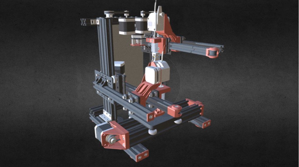
[7/13/17] - finished overall assembly


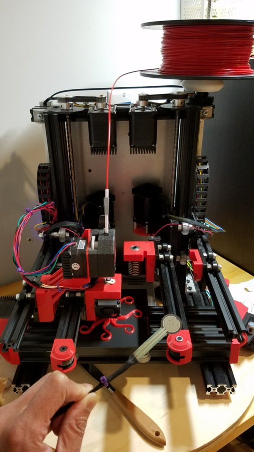
[9/1/17] - Actual build looks like
[12/27/17] - Full assembly upload to sketchfab. Click image below to view printer in 3D via web
ZideX 3D printer by stepcia - 3D model
This section saved for Y axis development:
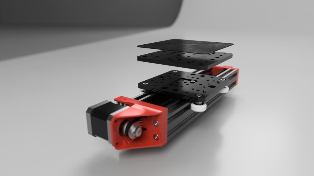
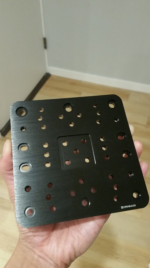
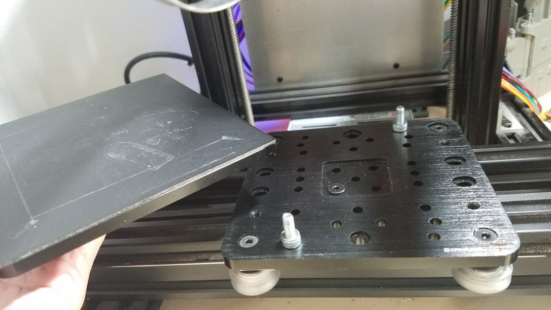
Prusa i3 arguably has the most common 3D printing bed size. well I find that I actually very rarely print at that size. most of my print actually fit in my palm size. So, the C-Beam Gantry Plate - XLarge seem to be the perfect fit and thus this Y bed is design around this plate.
I also want the bed to be removable for those low print that could be difficult to remove. the use of double XLarge allow the top plate to be removed by M5x8 screw there are 4 M5 tapped holes on the plate.
The recommended print surface is Zebra skin from Printinz. This has been tested for durability and I like it very much. Blue painter tape is too easy to rip.
Other bed alternative that have been considered but ultimately didn't make it are as follow. These are not necessarily better, just not aligned with the project goal.
- Dauerdruckplatte; Obviously German... aluminum plate impregnated with PEI. these plate are awesome but useless without heated bed...
- Mic6; too heavy and require custom cut for the size of this project.
- PEI thin sheet like prusa MK2. Again useless without heated bed
- Printbite; these are also awesome. It perform better than PEI and require less heat. but still useless without heated bed.
- Ok other alternative that will work without heated bed would be.... blue tape and buildtak. they are both consumable so not preferred.


See yup this is big enough
Attaching the build plate to Y gantry. Note the small magnet I added in the middle of the build plate. Since the plate has this recessed area the magnet will be housed inside it. We will need this magnet to hold the FSR in place for Z probing/homing

This section saved for X axis and U axis development:
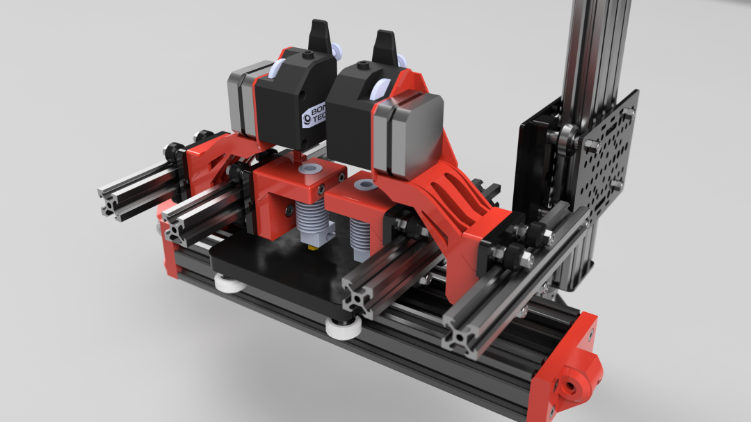
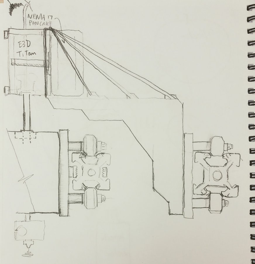
The x carriage will be moving fast and rapid in an overhang arm. So, weight will be a factor. I have tried bowden and had some success but my conclusion is avoid if possible. I know adding direct motor to the x carriage will have severe impact on X travel speed so I came up with a way to separate the Motor from hotend but still in the same axis; it's a parallel X arm connected to the same Z carriage. Since we will have a total of 4 arms I should think about naming these arms so it's easier to describe and follow.
Arm 1 carriage is driven by Arm 2 carriage connected via short bowden tube from Bondtech BMG to hotend. Arm 1 and 2 are connected to the same Z carriages.
- Arm 1 = X-Flying-Arm; this axis has no belt and its carriage is holding the extruder motor carrying Bondtech BMG as close as possible to the hotend
- Arm 2 = X-Motor-Arm; this axis is connected to the actual x motor with belt. the carriage on this arm is carrying the hotend.
- Arm 3 = U-Flying-Arm; dual extruder same description as above
- Arm 4 = U-Motor-Arm; dual extruder same description as above
Here's my initial sketch:
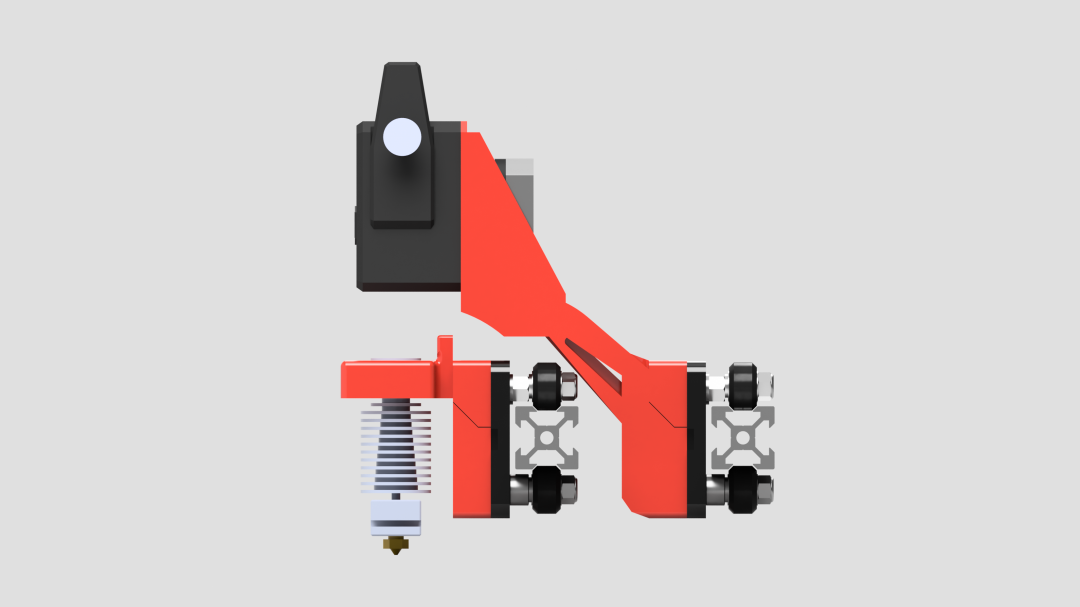
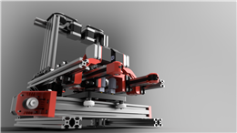
Followed by rendering


[08/13/17] actual assembly
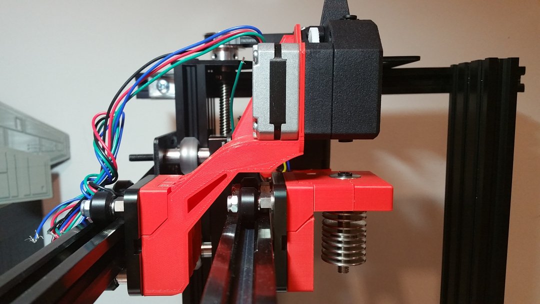
Attaching X motor to Z carriage is also tricky. I did not want the motor to protrude beyond back of the printer so I have to offset the x motor within the footprint of the printer
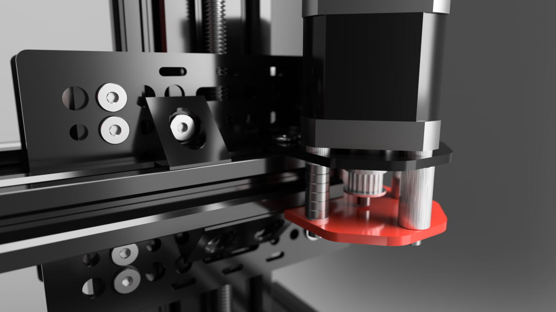

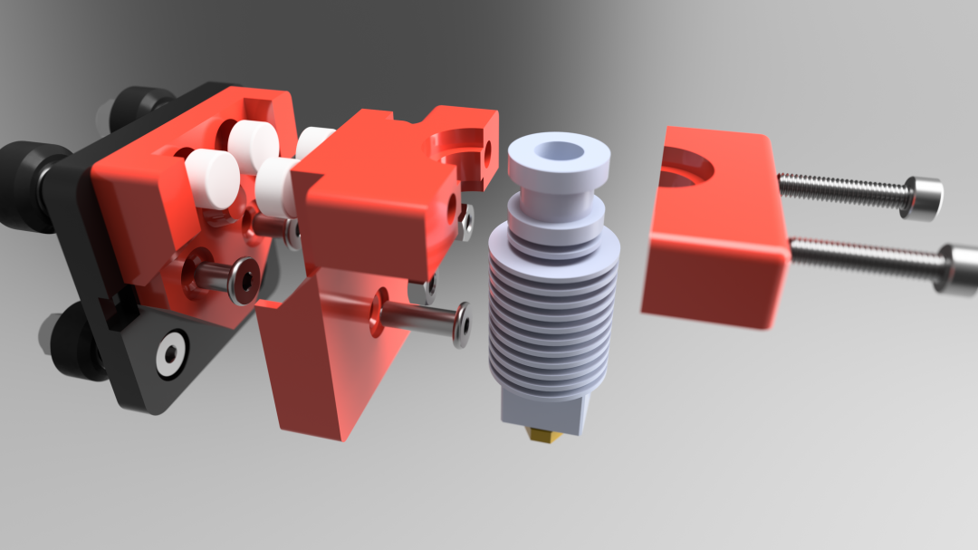
Attaching hot end to X carriage in an exploded view below. Note that I'm using 4 round Neodymium magnet (5mmx10mm) to allow switching to different toolhead easier. However, I have discovered that these magnets while it is very strong, there is a chance that the hotend can swivel ever so slightly in the X-Z plane it is not easy to swivel but it is possible when that tip of nozzle hit a curled up overhang layer....
Obviously we don't want any chance of the nozzle moving. so I have added M5 screw below the magnets to lock in place. Now the hot end will never move even if nozzle hitting print.


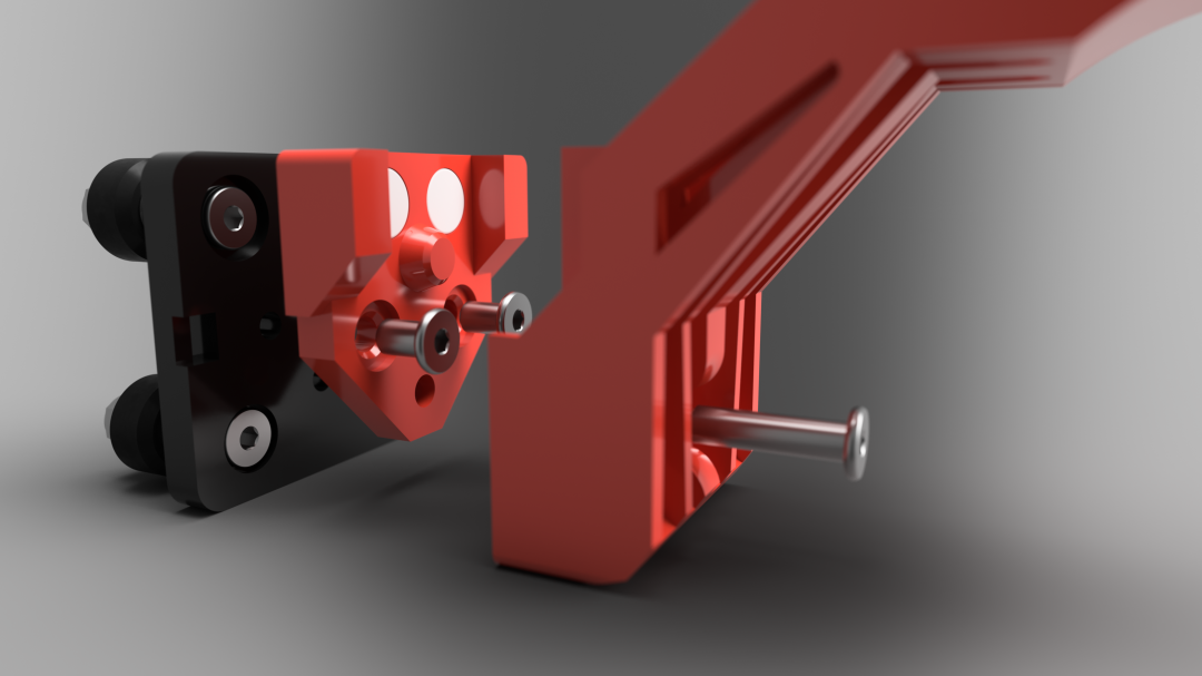
Attaching the flying extruder holder to the Arm 1 carriage


This section saved for Z axis; Tower1 and Tower2 development:
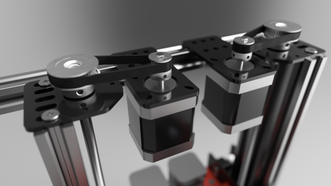
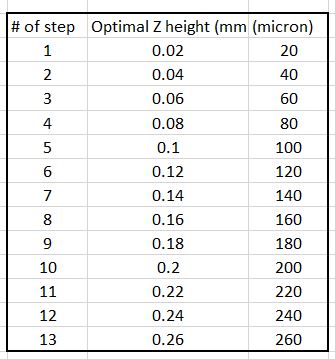
The z tower uses the stock openbuilds nema 17 lead screw actuator as base design. I modified the motor placement to the side to save space so it doesn't protrude beyond the top of the printer. This is a good opportunity to use reduction pulley. I have chosen to use 40teeth and 20teeth reduction. With a regular 1.8deg motor, this will increase the Z resolution of Tr8*8 lead screw to a factor of 0.02mm per full step so the optimal z layer height for printing would be in a factor of 20 micron
I don't recommend the use of 0.9deg to drive the Z axis. the overhang arm carrying all that X component perhaps would be too heavy given that generally 0.9deg will have a lower torque than 1.8deg. Plus there really isn't any practical benefit of the increase in resolution 0.9deg motor can offer since we already get good resolution with combination of 1.8deg and pulley reduction
This arrangement yield theoritical printable volume of 125 x 125 x 150mm. All of the crane style printer I've seen inherently has no support at the top of tower because they don't have place to support it.... I tried leaving the top of towers unsupported but no matter how secure I mate them at bottom, if some force is applied latterally you can see the tower tilt ever so slightly. I know its very small movement but I want to avoid it so since I have two towers, I can use another extrusion to bridge the top of towers. Now nothing moves
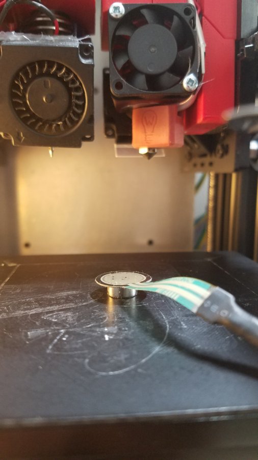
The advantage of independent Z is to be able to home each nozzle separately and take out the guess work of Z offset. In order to do that, I'm using JohnSL FSR board for the Z probe. I only need 1 FSR. First I home Tower1 and park the 1st toolhead and then I home Tower2. This would effectively set the exact same Z0 for both nozzle relative to the bed surface without trial and error. Of course the donwside is that you have to make sure the nozzle is clean and free of filament before you do home Z and it's not automatic you have to manually intercept with FSR before the nozzle hit the bed.
Further development involving neo magnet. While manually holding the FSR and aiming it hopit the nozzle will hit it will works, I have so far missed twice... Causing the nozzle to keep digging into the bed... So I've come up with somewhat easier workflow. Attach neo magnet in the back of the FSR and update the Z trigger height to around 10mm +- 0.05mm


This section saved for the machine structure development:
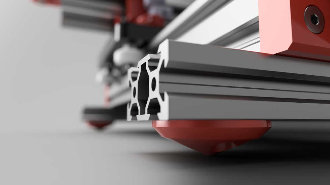
To further reduce noise caused by vibration transfer to desk, the feet of the printer should be pointy. This was inspired by a quite pricey subwoofer I've seen which had metal pointy feet. I believe they have done their research

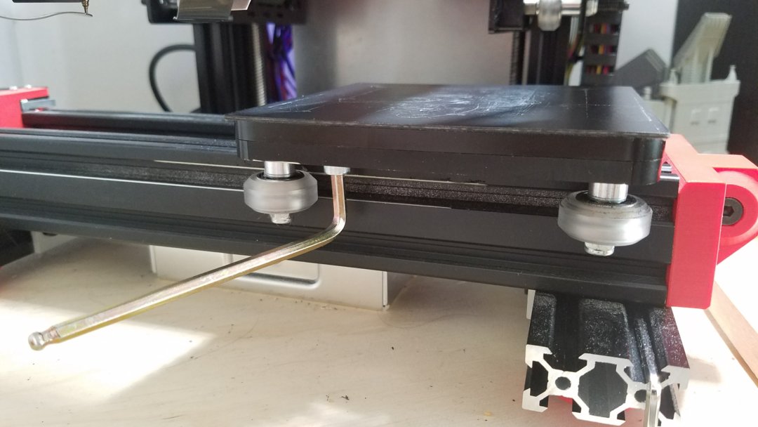
This section saved for print removal options
With removable bed, this is how you remove print effortlessly
This section saved for Dual extrusion and hotend development
First of let me address the obvious question; why not use Y splitter with single hotend and save yourself additional motor, axes and nozzles offset calibration? Answer:
Now with the ZideX separate nozzles, my hope is that I can avoid priming tower altogether. I can maintain the nozzle pressure while parking by pitting the nozzle against sheet metal attached in parking position to avoid leaking. But I do have to go through nozzle offset calibration which I know can be a pain to do. Once X,Y and Z offset calibrated there should be no reason to revisit this routine again.
- You can't use PVA and PLA with the same nozzle. Both material have different temperature extrusion. we don't want to cook the PVA
- Same nozzle means priming tower is a must. This tower can be as heavy as the printed object which mean you probably have doubled the printing time.
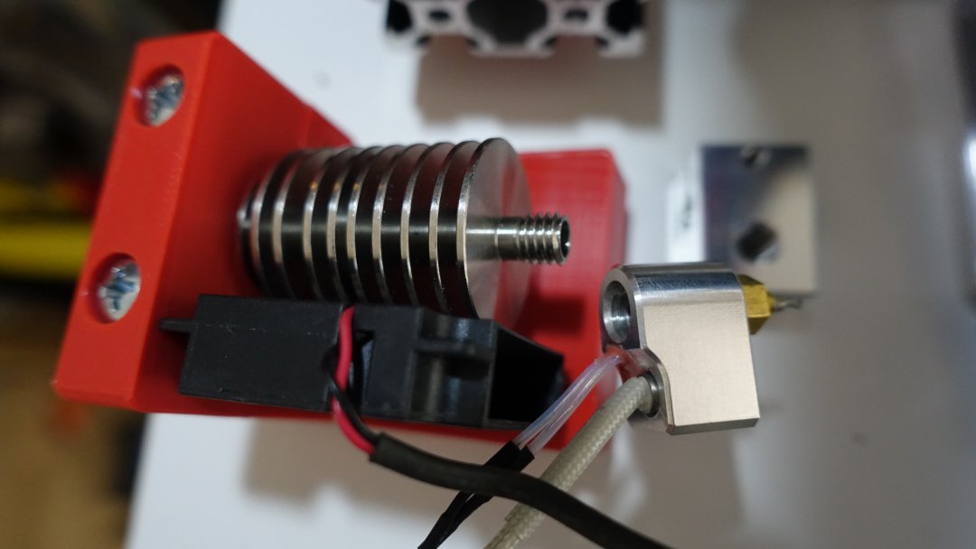
Hotend of choice is a hybrid combo. Use E3D heatsink, Rene's heatblock with airbrush nozzle. Don't use E3D heatblock and their nozzle. The issue with E3D heatblock is the size radiates too much heat onto print and cause simple thin overhang layer to curl up. That is bad for achieveing fine detailed print. Rene's heatblock nozzle adapter adds extra distance from tip nozzle to heater block which helps eliminate heat radiation issue.
This section for electronic and firmware
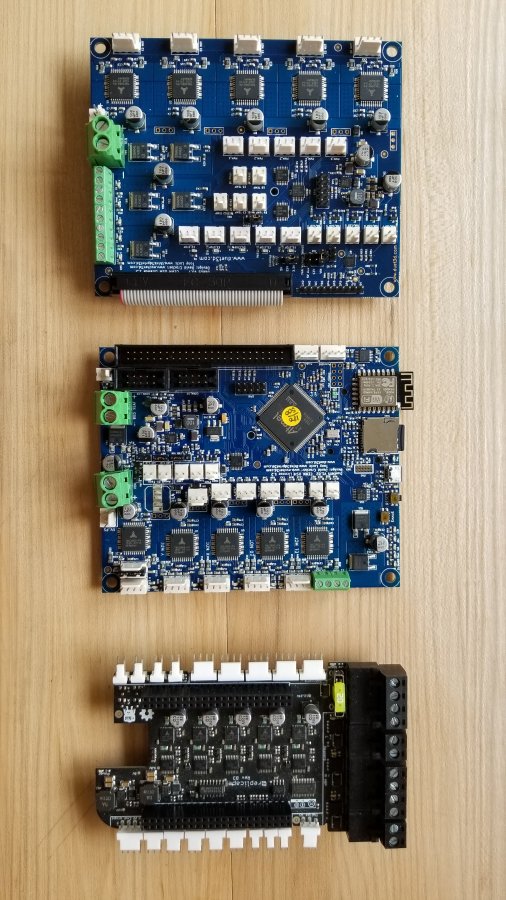
3 boards were considered for ZideX.
They share these common important features I need; 32bits, quality component, and trinamic driver. Well the cohesion is plug in driver while the other two are built in.
- Duet Wi-Fi
- Replicape
- Cohesion 3D
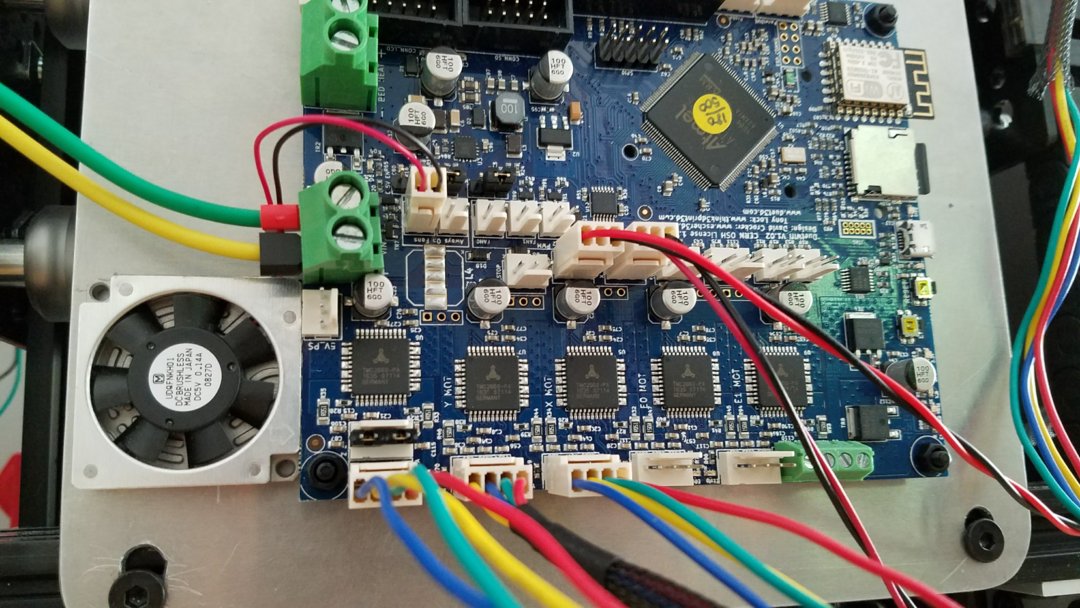
For this project I've chosen to go with the Duet WiFi mainly because the firmware development seems to be a lot more mature and the beta firmware as of this writing seems to support independent Z endstops. I will update this section more when it comes to that point
Openbuilds slim power supply slide underneath. I found a leftover aluminum plate that fits just right as the back holding electronic. It doesn't have to be aluminum on fact I planned to get a plywood cut out a nicer wood. I think wood and aluminum would go nice together.
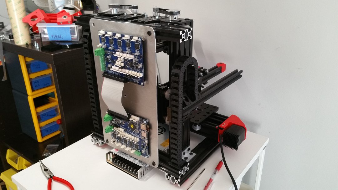
This might not be necessary as per Duet recommendation you will need active cooling only when you run current to you motor at 2amp and beyond. I don't plan on getting that close but I do like my electronic cool so, here you go this is totally unplanned. I just happened to use 6mm nylon standoff and have a 6mm thick fan
ZideX
Build in 'Cartesian Style Bots' published by stephen cia, Feb 7, 2018.
3D printer with 7 drivers, compact, dual extruder, no CNC part. All Openbuilds and 3D printed part. This is purely experimental.
-
-
Build Author stephen cia, Find all builds by stephen cia
-
- Loading...
-
Build Details
- Build License:
-
- CC - Attribution NonCommercial - Share Alike - CC BY NC SA
Reason for this Build
to have fun
Inspired by
Indie I2, Bukito and all other crane style 3d printer that I don't remember the name -
Attached Files:

