
Back again with Yet Another Workbee Modification. Lots of people seem to complain about the Workbee having minimal Z axis clearance. Normally it's around 3" or about 80mm. This mod involves recessing the bed to give another 20-25mm of Z axis travel. It can easily be accomplished with an existing build or a new kit build.
Let's get started. The Workbee base assembly has two 20x40 beams across the front and back, which normally support the bed and 20x80 beams under the bed that support the board on the sides. The 1010 has an additional support beam in the center.
The Workbee supposedly can be set up with 2 different bed configurations, I never did understand the use of the higher one. It just places the bed way too high in my opinion, and reduces the already insufficient Z axis travel by another 20mm. This is supposed to make the machine stiffer, but IMHO it would make very little difference. Just reducing the moment arm on the Z axis by 20 mm seems like it would have negligible effect on the X/Z axis stiffness.
So, anyway, this mod gives another 20mm of Z travel, which is very handy for the Workbee and much needed. If you have read my other Workbee Modification, (Some Improvements on the Workbee 1000x1000) you already know I increased the stiffness of the base by taking the two 20x40mm "legs" that are supposed to be mounted under the outside 20x80 supports, rotating them 90 degrees and spacing them equally between the front and back rails. This requires cutting off a few mm from these rails so they don't interfere with the inside Y gantry plates. They are attached to the sided of the 20x80's with 4 hole angle brackets. This stiffens the whole base assembly, and it then rests on 4 full length 20x40 supports .
I looked at this arrangement, and it occurred to me that if I recessed the spoil board by moving it down between the front and back rails, I could increase Z axis travel. I eliminated the 20x40 crosspieces under the bed, and attached the 20x80's with cast corner brackets on each side. The 20x80's are in the same position, but mounted on the bottom slots of the front and rear supports instead of the top.
The bed board is held in by a row of tee nuts with screws on each side of the outer 20x80's, similar to my other design. A series of 2 hole corner brackets secure it to the central 20x80. This is a bit less robust than the original setup, in terms of bed stiffness. This should not be an issue as long as you have a nice flat table to set the machine on.
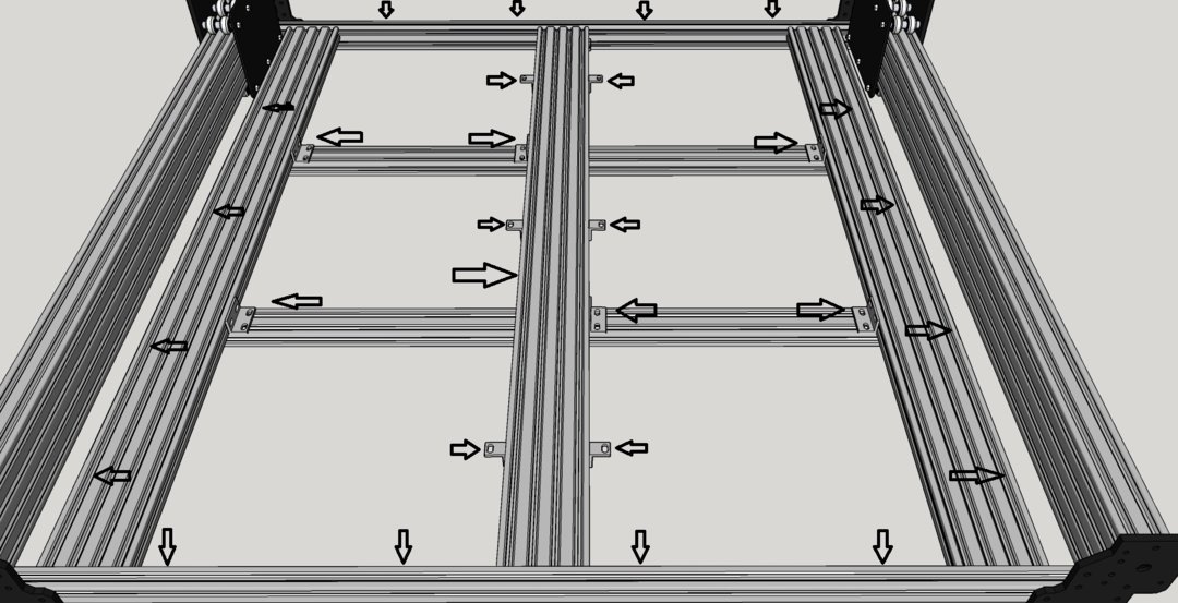
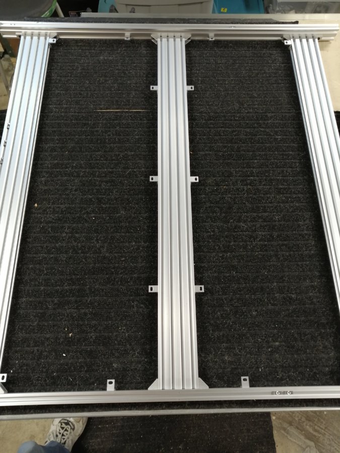
Here you see an image of the base assembly as modified. You can see the attachment of the 20x80's using cast corner brackets. Make sure to square up the whole assembly and then do a final tightening of all the screws.
If you look closely on the left of the above image, you can see the 4 tee nuts I put in the side 20x40's to hold the edges of the bed board. These are also shown by arrows in the first image. They are out of the way here, and the screw heads will not interfere with the router as it can't reach them during normal operation. Note that the tee nuts are "upside down" with the extruded thread boss facing up, this makes it a bit easier to put in the screws and gives a bit more thread engagement. Drill holes 10mm from the outside edge of the board for the screws. For the other build, I space them at 200mm distance along the 20x80's, for this build, the board is 40mm shorter, so the outside ones are 180mm from the ends.
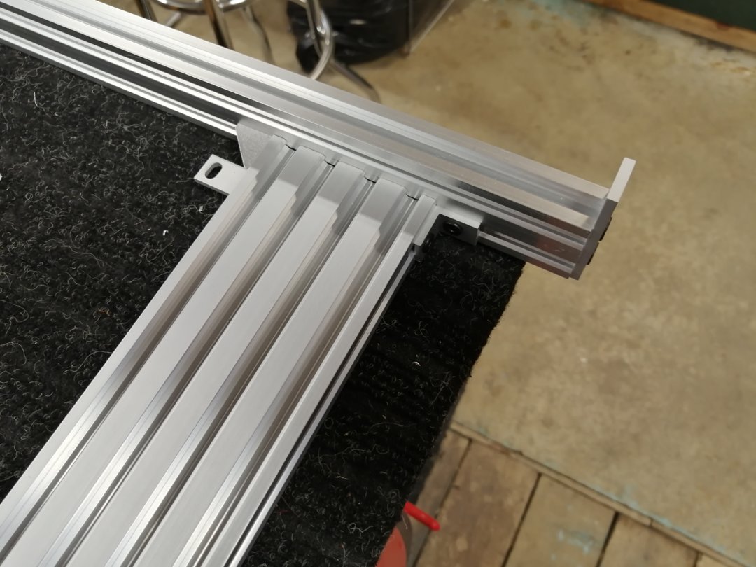
This photo shows the outside corner of the frame. the Y axis c-beam will sit on the front and rear crossmembers at this location. Note that the outside support for the 20x80 is a 2 hole corner bracket instead of a cast corner bracket. I found that the cast ones interfered with the inside gantry plate and reduced travel by a few mm. Note also that instead of the black 2 hole flat plates that are supplied with the kit for purely cosmetic reasons, I use a 3 hole plate. This makes it easy to center the c-beams, and gives a bit of extra support. You need to place an extra tee nut at each outside end of each c-beam. Note that to use these, your front and back rails must be exactly the same length to avoid getting the c-beams non-parallel, which would cause the carriage to bind up. The length on these is usually exactly 995mm. This also assumes your X axis beam is exactly 1000mm long.
That's pretty much all there is to it. Cut the bed board to 960x875 instead of 1000x875. If you use a 5/8" (16mm) MDF board, there is a bit of a lip front and back on the bed. This is actually handy, because if you use a piece of 1/4" hardboard for a spoil board, it fits nicely in between the front and back rails. A few pieces of double sided tape are all you need to hold it in place.
If you like the original modification for the extra bed stiffness, there is an easy way to maintain it while still having the recessed bed. It just involves replacing the front and back 20x40 beams with 20x60 beams. Then the bed can be built identically to the original, or with the other modification mentioned above, while still being able to use the recessed bed. The c-beam end plates will just go in the top two v slots on the 20x60.
YAWBM - Yet another Workbee Modification
Build in 'CNC ROUTER BUILDS' published by Metalguru, Oct 6, 2020.
Increase Z axis travel by 20-25mm with minimal modifications
-
-
Build Author Metalguru, Find all builds by Metalguru
-
- Loading...
-
Build Details
- Build License:
-
- CC - Attribution - CC BY