
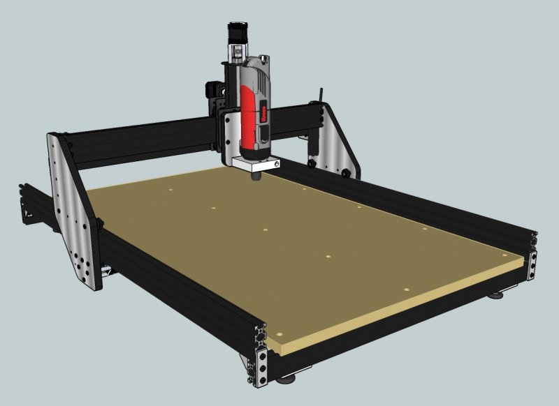
Overall size machine 101 x 72.5 x 54 cm (39.7 x 28.5 x 21.25 inches)
Milling boundaries XYZ: 57 x 79 x 9,5 cm (22.4 x 31.1 x 3.75 inches)
Features:
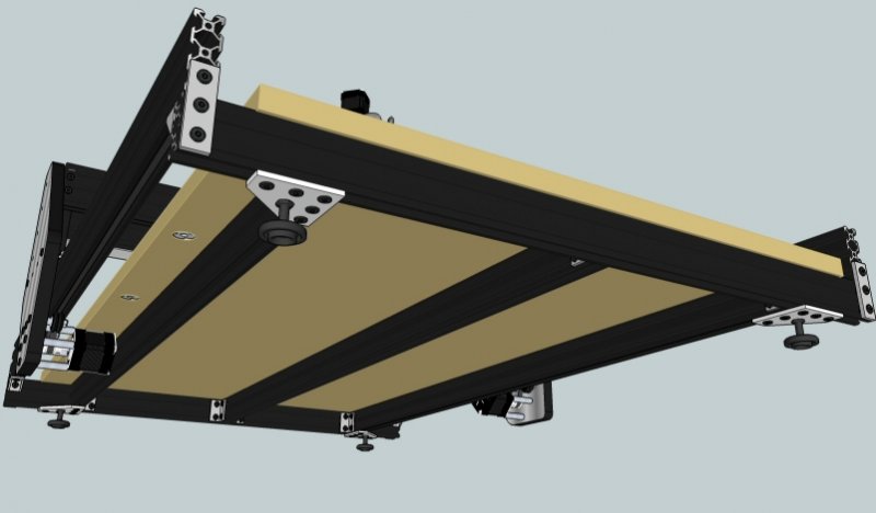
- height adjustable X axis bar
- Y axis motors underneath bed
- Y axis motors turned 45 degrees (saving some height)
Inspired by the Routy (Gantry carriage, height adjustable gantry) and the Frog (custom gantry plates, belt tensioner)
Experimented with belt tensioner from the Frog, but does not seem necessary. Manual tensioning and reverse T-nut works perfect. The Frog tensioner is also a bit 'weak', imho hanging on the outside (i have to move the machine a lot)
I used regular aluminium profiles in various places;
cable gutter, brackets for limit switches, cable clamps etc.
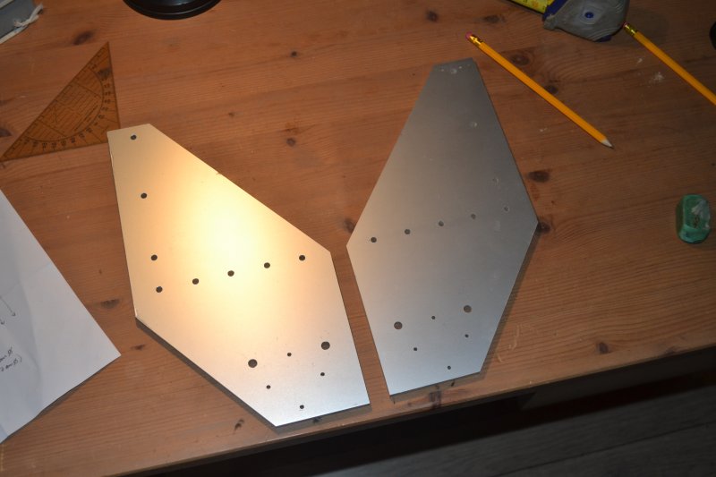
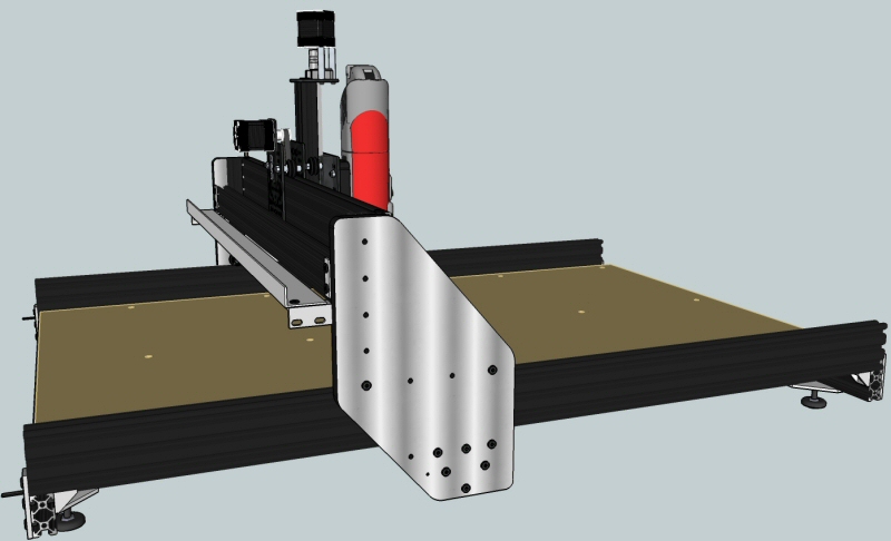
When building, i had no acces to a cnc machine. I build my gantry and z-axis plates from 6mm MDF sandwiched between two sheets 1.5mm aluminium, glued with epoxy resin.
It is both light and stiff.
Note: My first version was only one sheet of aluminium and 6mm MDF. The MDF was not strong enough and gradually, the holes on the MDF side became bigger (causing play on the v-slot wheels)
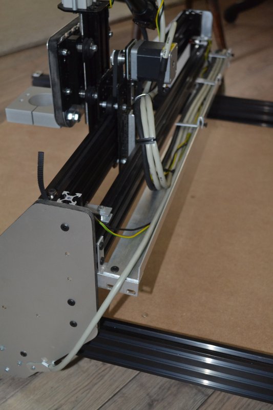
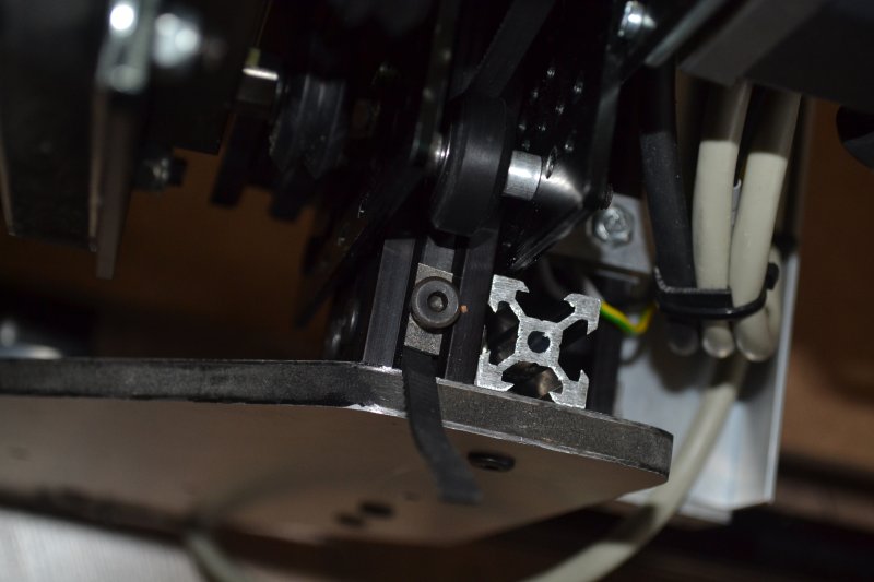
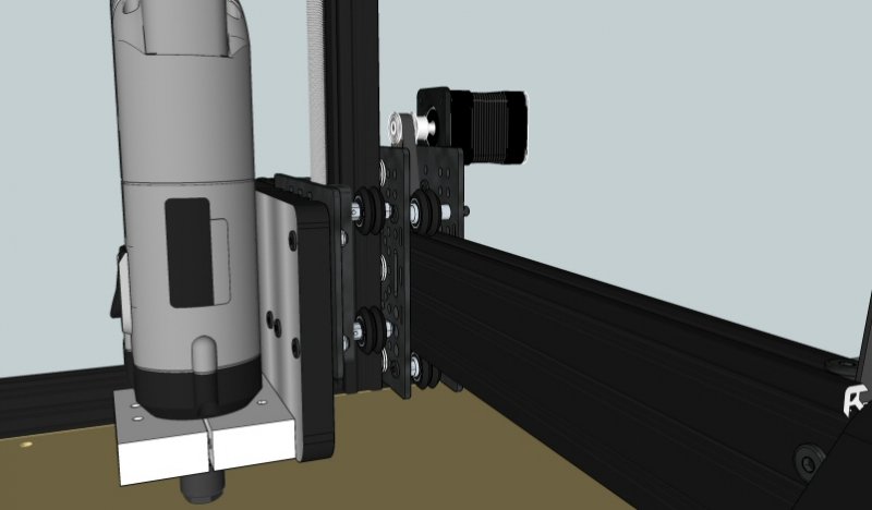
Two vslot extrusions are used for the x-axis for extra sturdyness
I drilled holes in these bars to mount them directly without L-brackets. This way I achieved an extra 4 cm x-axis travel.
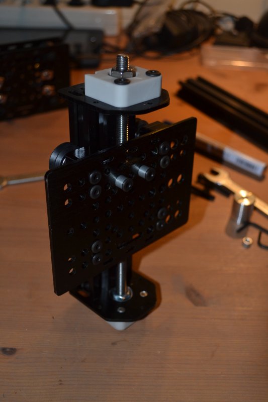
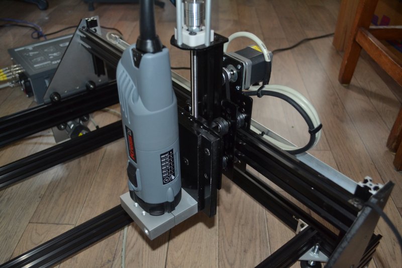
A Polished stainless M10 leadscrew is used on the Z-axis. No bearing mounted on the bottom means extra Z-axis travel.
The Sketchup file is not entirely correct (most T-nuts are missing for instance ;-)), but i hope it will inspire others.
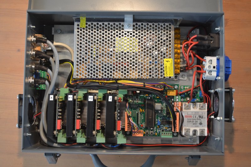
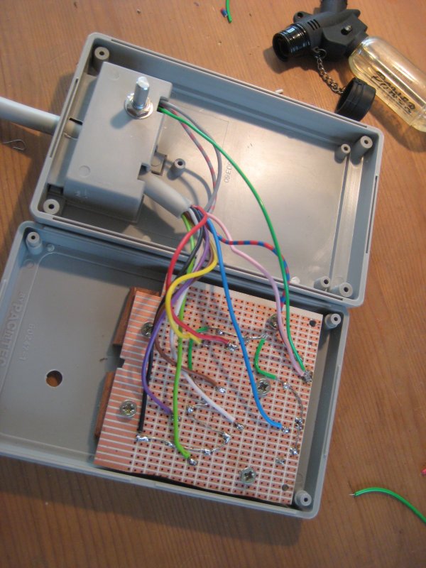
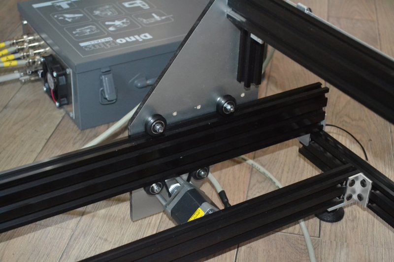
Control box was already finished when my openbuilds stuff arrived (had to wait for it a few months due to being out of stock and shipping to the Netherlands)
I used a universal tool case for the box. (bought empty for around 12 euros)
It houses the power supply, controller board, motor drivers, solid state relay (for spindle), and a DC stepdown converter which powers 2 fans.
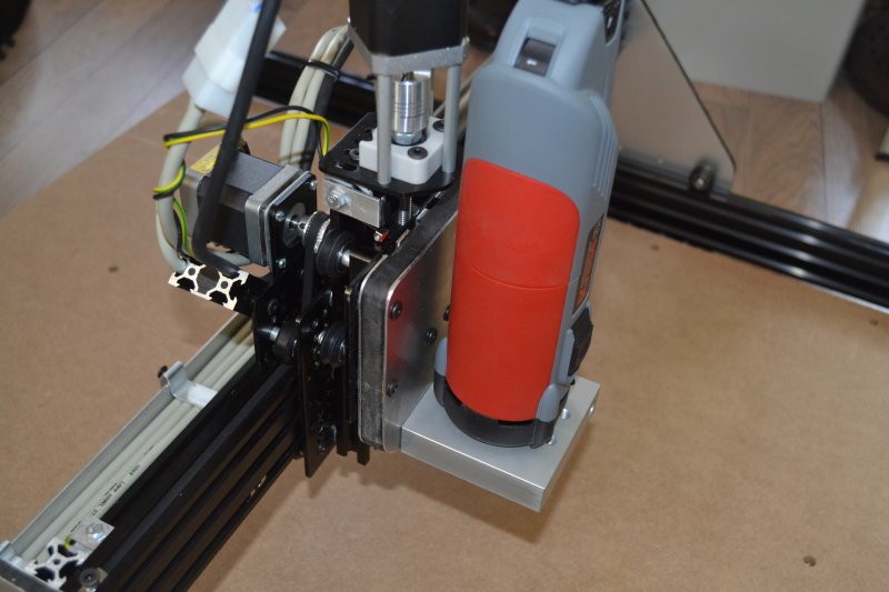
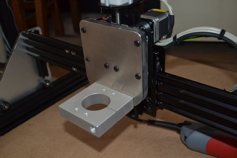
The mounting block for the Kress is a milled from a solid block of aluminium and bought "of the shelf".
My main tools for building: Drill press, small vice and hand miter saw..
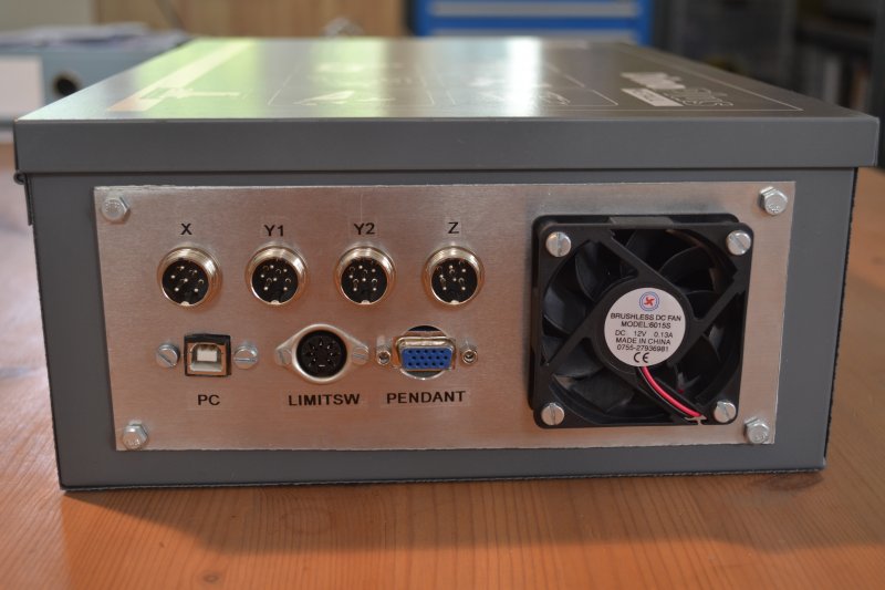
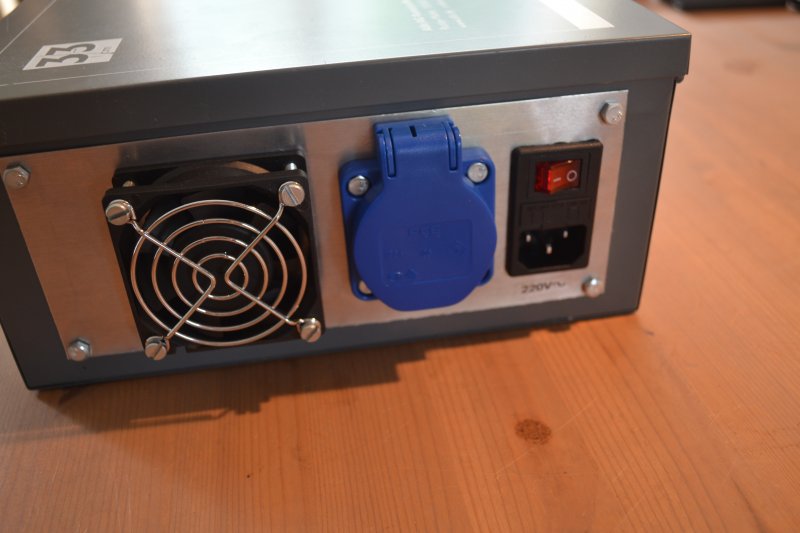
The control box:
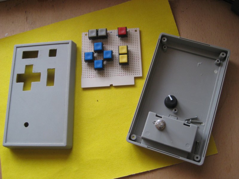
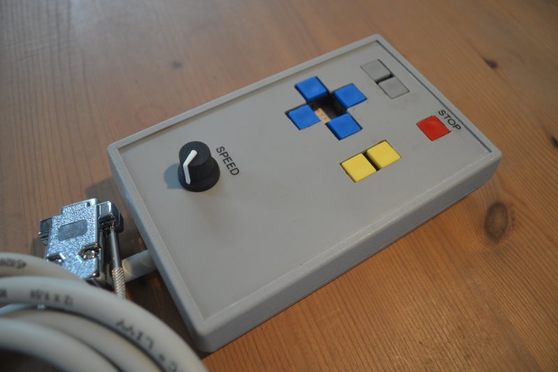
The home build pendant controller:
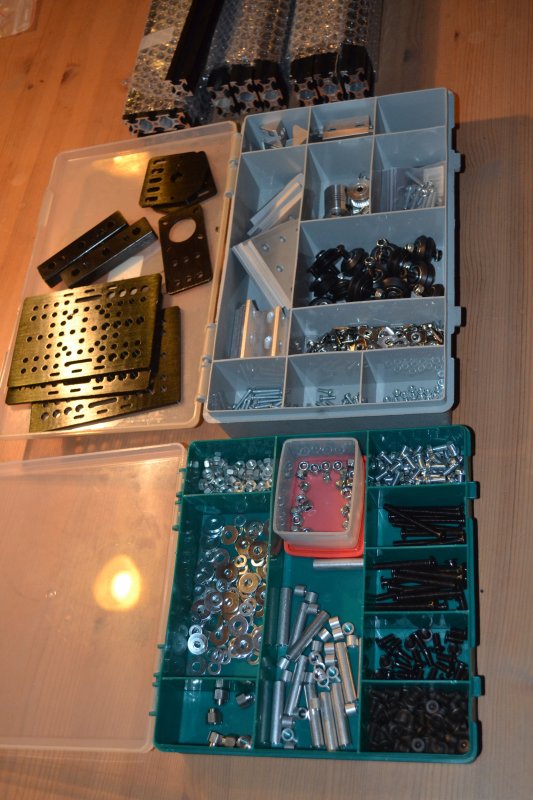
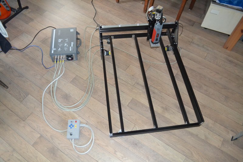
Finally it has arrived! Let's build something
First version of the Z-axis with bearing at bottom (too little travel):
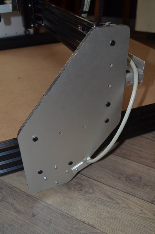
First version of the gantry plates (single side aluminium) :
(next version is double sided aluminium and slightly wider thus more stable, but loosing some Y axis travel)
Z-axis carriage. M5 nut pressed into the delrin block gives a flat back side:
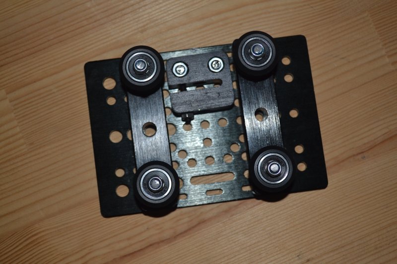
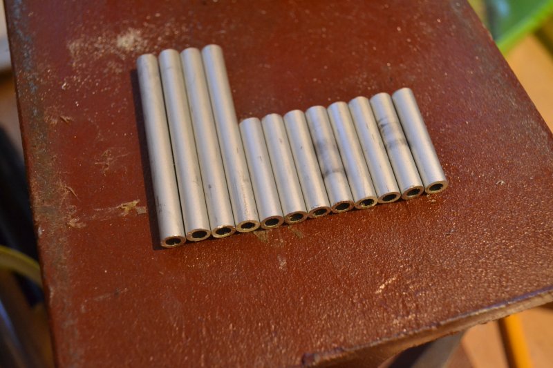
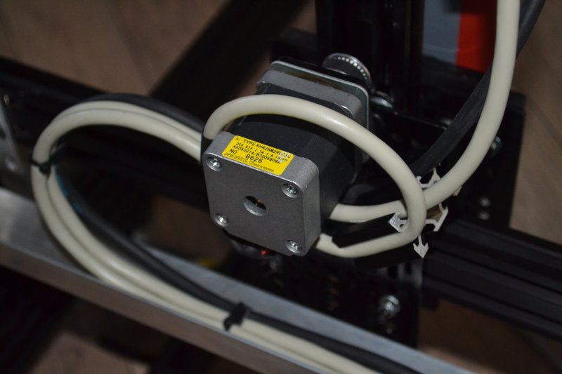
Custom made spacers for the stepper motors:
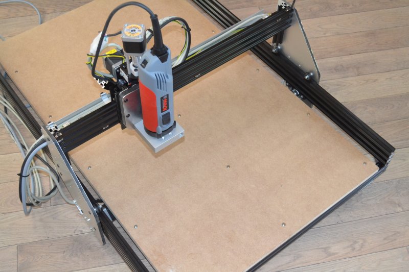
Ready for a test run:
Simple and easy for tensioning the belt:
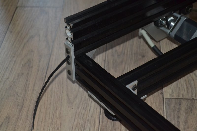
A small peace of 40x20 serves as a cable guidance:
The first version of one of the gantry plates:
First version of the Z-axis plate:
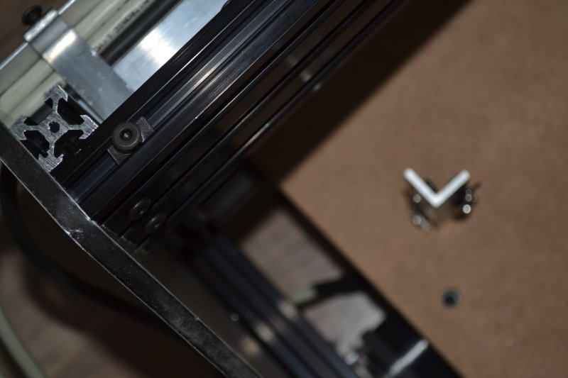
The L-bracket prevents the X carriage to move an extra 2 cm:
Mounting the beams with a bolt trough some drilled holes solves this:

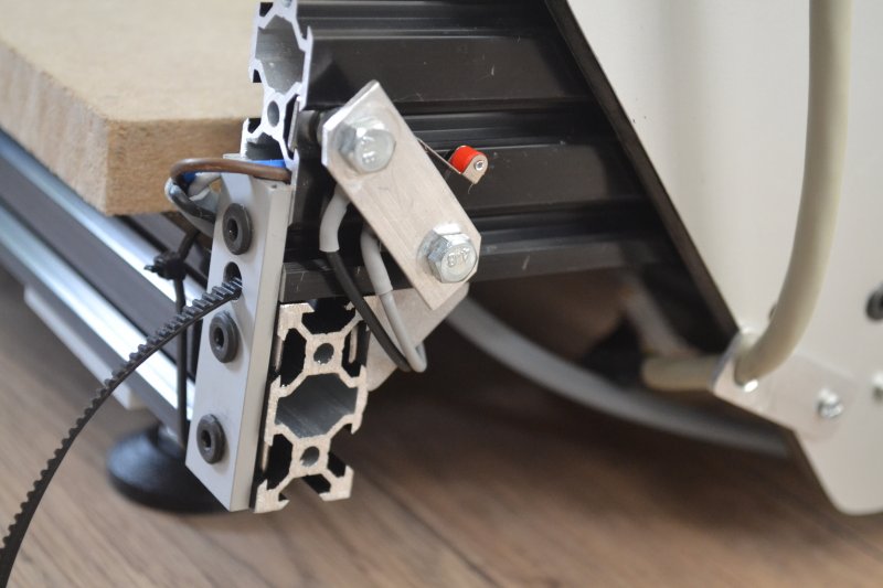
Still a bit untidy, the Y- limit switch :
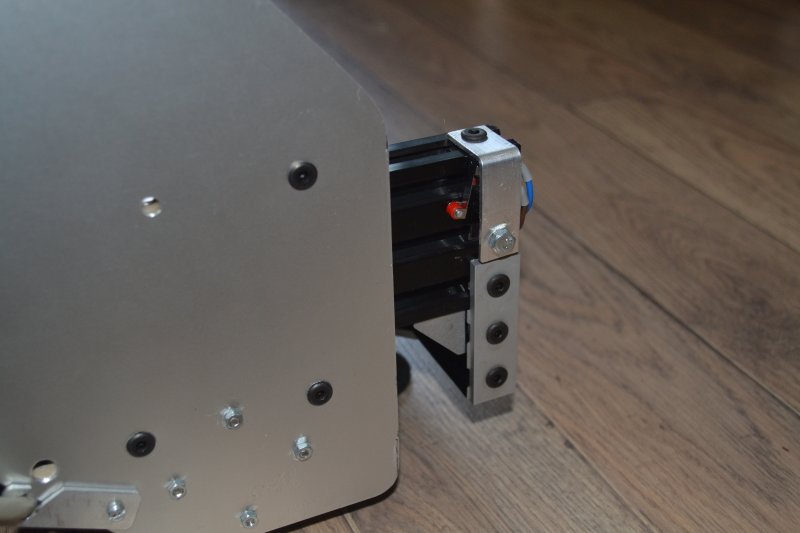
The Y+ limit switch:
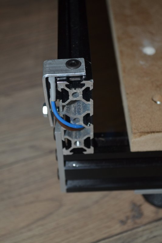
One of the two X-limit switches:
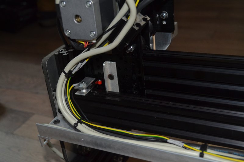
A look at the cable gutter with 3 adjustable aluminium "bolt on" cable clamps:
Overview. 18mm MDF bed installed (not fixed yet):
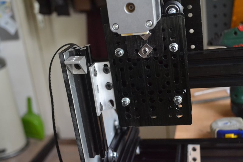
Some details of the X and Y carriage (also shown is the Z+ limit switch):
A small bolt on cable hook:
The X carriage at its most righthand side position, limit switch activated:
The current Z-axis mounting plate with the kress mount bolted to it with 2 M8 bolts (back side)
The sketchup design:
Things i would do different (and i probably will change that in near future) :
The Y limit switches are mounted on the fixed part of the table, all other cables are mounted on the movable gantry. Mounting both Y limit switches on the gantry plate gives one neat bunch of cables to te control box. Now the limit switches cable is a split cable, going to gantry an to the fixed table..

YAOR (Yet Another Openbuilds Router)
Build in 'Cartesian Style CNC' published by winand, May 31, 2014.
Yet Another Openbuilds Router, my version :-)
-
-
Build Author winand, Find all builds by winand
-
- Loading...
-
Build Details
- Build License:
-
- CC - Attribution NonCommercial - CC BY NC
Reason for this Build
Just for fun! I like to build things..Inspired by
Routy & the Frog -
Attached Files: