
Initially, i had ordered a Phoenix 3D printer (see this "build")
After 8 months aftfer ordering, i was tired of waiting and cancelled my order. Unfortunately the company went bankrupt and i've lost all the money i payed for it (over 500 usd incl shipping)
After this debacle i decided to build one myself.
Openbuilds material would be a perfect basis, so the printer is build with Openbuilds stuff along with various custom made aluminium plates.
I've done my best to make the printer a solid and sturdy as possible, also, i wanted to maximize print head travel beyond the edges of the build plate. This can be very handy when making use of filament scrapers (nozzle cleaning) and a bed leveling probe.
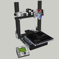
I wanted to get rid of the most often seen X motor on one side, pulley idler on the other side. I've made my X axis motor stationary in the middle of the X axis,
moved the Z axis lead screws to the back and voila, the whole width of the printer is available for moving the gantry
(added bonus; Motor in the middle divides the weight of the motor equally to the two towers)
The Y-travel of the print nozzle also goes beyond the bed edges. The bed extends further than the depth of the printer (front and back). In theory, i can print up to 270mm(x) by 230mm(y) when i put on a bigger glass plate (no heating, so only PLA then)
I have made the graphical LCD control box separate which will magnetically clicks onto the steel front plate of the printer. (little idea i got from Werner Berrys nicely made Berrybot)
Just like my CNC router (YAOR), i was keen on putting the electronics as neatly and compact as possible. I really don't like all the PCB's fixed with tie wraps and wires hanging everywhere, separate power supply etc etc.. I just want one compact printer with a 220V lead and a USB lead
After building, calibrating the axes i went on and did some tests heating the hotend and bed. The bed was struggling to heat up to 85`C, which is not enough for ABS :-(
To solve this, i modified the RAMPS 1.4 board. I replaced the 11A polyfuse by a regular 15A car fuse and made a little heat sink for the FET. In my revision2 box (1cm higher), fans blow air directly on to it from the side keeping the lot cool.
After this modification heating went up to 95'C. Still troublesome for ABS. Then i thought that my heatbed is an aluminium version mark3 which i bolted on an aluminium plate with some alu stand-offs. (no adjusting needed when using auto bed leveling)
This connection is a big heat conductor causing the bed beneath also to heat up equally :-O
After running tests without the bolts and spacers, I can reach 105'C now, hoping that will be enough.
Note: I have ordered some nylon M3 screws and stand-offs now which will soon arrive.
Build is as good as complete now, still, haven't printed anything.
Filament is ordered yesterday, so i'll be tweaking software soon
Features:
- One neat electronic box at the bottom, bottom plate detachable for maintanance
- Z motors and leadscrew at the back of the Y columns, leaving max x-axis travel
- graphic control ia a separate box, attaches to front panel magnetically
- X axis movement not restricted by distance between Z columns
- Y axis movement not entirely restricted by printer depth
- printer bed is 205mm by 205mm, reachable by nozzle: 270mm(x) by 245mm(y)
- compact dimensions; 350mm wide, 310mm deep (electronic box only 220mm wide and 260mm deep
- printable volume: 205 x 205 x 235mm
(easilly expandable to 230 x 270mm with bigger glass plate if no heated bed is required)
- DRV8825 stepper drivers with 1/32 microstepping
- auto bed leveling (Marlin firmware) using servo
- E3D v6 hotend
- Modified RAMPS 1.4 board; 11A polyfuse replaced by regular 15A car fuse. Custom heatsink attached to FET
Marlin tip;
When engaging the Z probe with the servo, i noticed that the angle of the probe was not consistent every time. If i gave a second engage command (M401), the servos position would be accurate every time.
So i changed the engage_z_probe() routine in marlin_main.cpp (from approx line 1094)
To make sure the routine is done twice in a row, just put the original lines of code between the following:
int k=0;
while (k++<2)
<ORIGINAL LINES OF CODE IN engage_z_probe()>
}
So now G29 also engages the probe two times.. Works flawlessly!
Sketchup design:


The real thing:


Check out the "Files" tab to download the SKP Sketchup file.
Don't forget to check the "discussion" pages of this build, any further updates will
be posted there!
YAOP (Yet Another Openbuilds Printer)
Build in 'Cartesian Style Bots' published by winand, Oct 29, 2015.
Yet Another Openbuilds Printer, my version :-P
-
-
Build Author winand, Find all builds by winand
-
- Loading...
-
Build Details
- Build License:
-
- CC - Attribution NonCommercial - CC BY NC
Reason for this Build
Like to build stuff")
Inspired by
Various 3D printers on the web. -
Attached Files: