
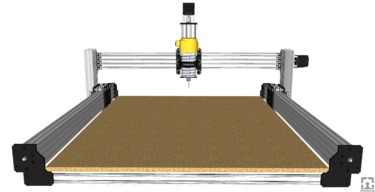
Since I have this strange malady whereby I can't leave anything alone, I present the WorkLead Machine, no wait, the LeadBee, Naw, I think I'll just call it the WoodWorker.
There are parts of the Workbee I like a lot, and there are parts that I don't like. Same thing with the Lead machine. So, I had this idea to Frankenstein the two together to form the WoodWorker.
The Workbee has several admirable traits:
It also has some less admirable traits:
- Lots of wheels
- nice mounting plates/motor mounts that hold the corners of the machine together
- great 4 hole end plates for the Z axis that allow sturdy motor mounts
- c-beam construction throughout
When the new Lead Machine came out, I thought "Finally, someone has come up with a machine that addresses some of these problems". Turns out it's kind of a yes and no thing. The Lead machine uses standard plates all around, which is great, but they kind of sacrificed some things to do this.
- The Workbee has poor base design. I never understood why anyone would sacrifice so much Z axis travel for the dubious advantage of a bit of stiffness. I don't think it would make a lot of difference. I have never built or recommended a kit builder to use the high bed design on this machine.
- Base has limited stiffness because of the 20x80's mounted flat across the bottom. The original only had 2 to support the meter wide spoil board, this was not enough. Current kits have 3, but they are still mounted with the 20mm profile doing the supporting, which is not very strong. I have addressed this somewhat in another build -https://openbuilds.com/builds/some-improvements-on-the-workbee-1000x1000.7431/
- There are a lot of compromises due to the ability to use both belt and screw drive. Enough compromises, that the design suffers for it. My opinion is that V-slot technology extrusions just aren't stiff enough to make machines larger than 1000mm in any direction. I strongly discourage anyone from making the 1500x1500 flavors of this machine, the long extrusions just are not stiff enough, compounded by the belt drive system which has a lot of belt stretch at these lengths. Machine performance suffers greatly in this configuration
But, enough griping, lets see the approach I took with this machine.
- The mounting for the Y axis beams leaves a lot to be desired. Only 4 corner brackets hold the whole beam in place. Not very strong.
- They still use the lame 2 screw motor mount. I don't like this arrangement at all, and I have been using custom plates to fix it for quite some time now. I recently found a supplier who could make these plates for me very cheaply, and I have been using them exclusively instead of the OpenBuilds thick end plates.
- The adjustable X axis height using v-slot instead of a gantry plate was great. I did this on one of my first designs about 3 years ago. I one upped this in this design, as you will see in a bit.
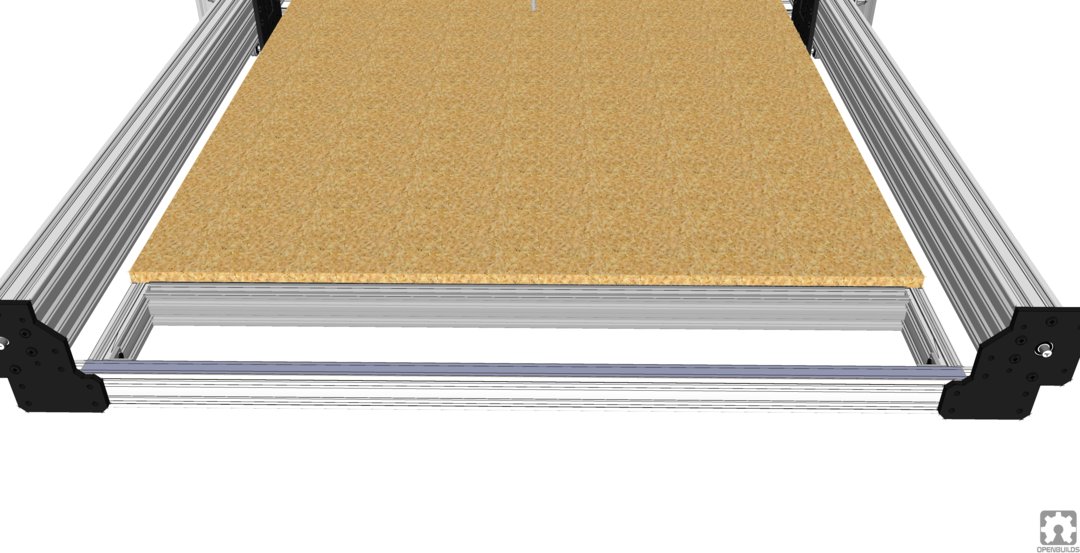
- I also added some support to the base in the form of an additional 20x40 support beam, using 4 instead of 3. I think base rigidity is important to ensure a flat spoil board and overall machine rigidity. If I was building one for me, I would use 40x40's instead of 20x40's.
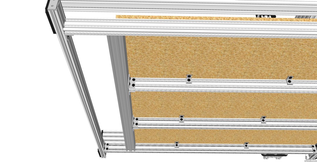
First thing I did was to replace the flimsy corner bracket Y supports with the Workbee end plates. This allows me to mount the motors using 4 screws, and is infinitely stronger for mounting the C-beam Y axes. It also ties the whole corner of the machine together nicely. This is one of the best features of the Workbee design, IMHO. The other thing I did was have my supplier put a 16mm thru hole for the lead screw bearing mount instead of the stepped hole that's in the Workbee design. This way, it is only one part, there is no left and right pieces. Less parts, easier manufacturing, lower cost. I just use a flanged bearing instead of the standard bearing.
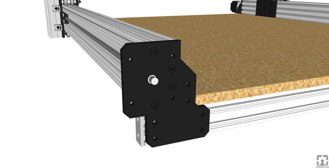
Note that I also added a 3 hole joineer plate across the end of the 20x40 front + rear legs, just to dress it up a bit, and unlike the Workbee, the third hole helps tie the leg to the c-beam.
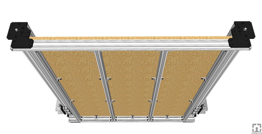
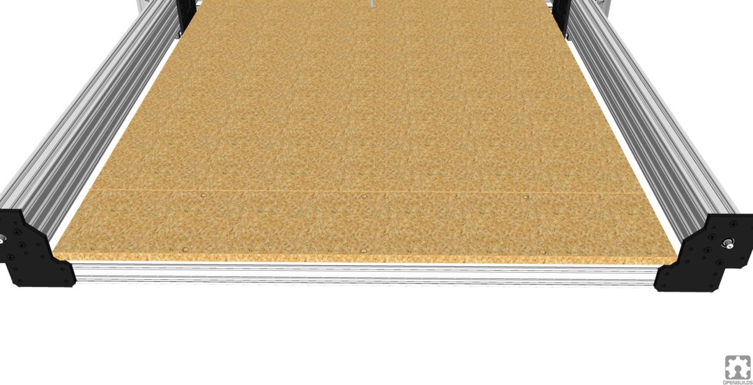
Next thing I addressed was base support. I added an additional 20x40 to the base. Just gives better support in my opinion. I added a couple more angle brackets to attach the spoil board as well. This is another shortfall of the original Workbee kits, there is no hardware to attach the spoil board. I include this with all the Workbee kits I sell. I still think I am going to use the thru hole screw attachment of the spoilboard that I have always used with my builds. I generally drill 4 holes thru the spoil board along each side, and three on the front and rear. The ones on the front and rear are recessed to avoid the screw head sticking up and holding up the end of a long work piece. These are a bit of a pain to line up, and I always forget to put some of the tee nuts in the top of the 20x40's, but worth it for rigidity. It makes the spoil board a stressed member of the frame. The screws in the center of the spoil board field are too much work to recess, so I just use angle brackets and screws from the bottom.
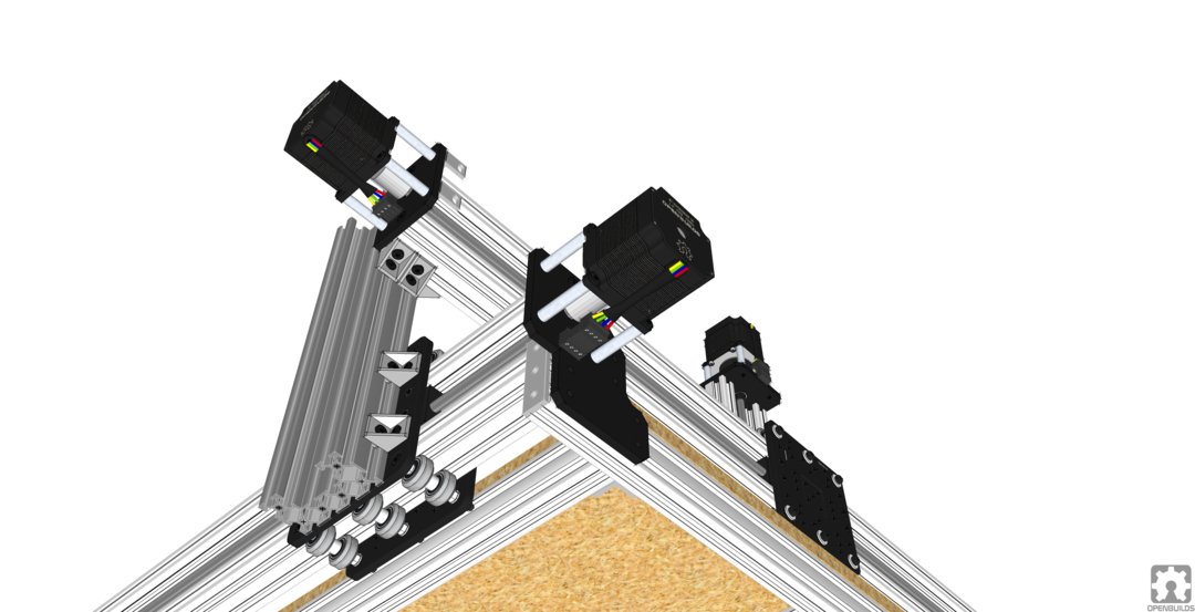
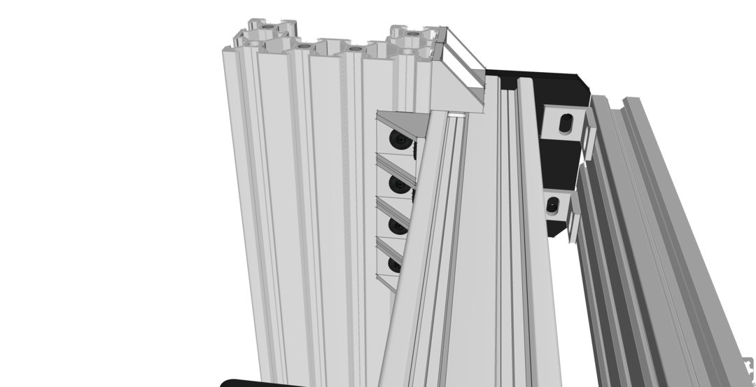
Now on to the Y axis carriages. I thought to my self, why not replace the 20x80 uprights with c-beam? Cant't hurt, right? Gotta be stiffer than a 20x80. But, now I have a decision to make. If I left the X axis mounting the same as the original, I wouldn't really gain anything. So, I decided to move the Y axis carriage in by 20mm on each side, making the bed 40mm narrower. This allows me to use 8 (count em', 8) angle brackets on each end to support the X axis beam. This should stiffen things up nicely. I also made the side c-beam supports 50mm longer, which allows me to put 2 corner brackets on the top of the x axis for additional support. This also raises the X axis up by about 30mm, giving full travel on the Z axis of 130mm.
I never liked the 3 cornered brackets to join the top of the axis to the uprights. They are wheel killers. If you run a polycarbonate wheel up against that sharp corner of the 3 corner bracket hard, it will crack the wheel every time.
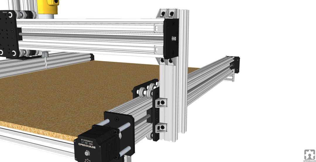
As you can see, the 4 hole motor mount is a big improvement.

Should be good and strong. As you can see from the last couple of pix, I also added the full complement of v-wheels. Not sure why OB left them out, it seems like a no brainer. Especially on the Z axis. 4 wheels supporting the Z is definitely not enough. So, the wheel count on this machine is 42, just a bit shy of the 48 on the Workbee. Good enough, though, I think. A couple more on the Z axis would have been nice,
I used Workbee 4 hole c-beam end plates for all axes, including the Z axis. Makes motor mounting SO much better and more stable.
Oh, and I added a 20x60 across the back of the X axis using 4 x 2 hole angle brackets to hold the cable chain and the electronics. Probably wont add much for strength, but it looks good.
The ability to adjust the X axis up and down on the supports is a great plus. You can lower it right down until its sitting on top of the Y gantry plates for maximum stiffness, or raise it to the top and get a full 130mm of Z travel. I think this is the best feature of this machine. The strength and stiffness should be as good as theoretically possible with the c-beam.
I did lose a tad off the width of the machine, about 40mm. This is not such a big deal, especially considering the bit on the router can reach just about the whole width of the bed when its mounted high. When it's lowered down, the width is a bit less, but not enough to worry about.
Now I gotta get out and build one of these. This is just a concept for now. I do have a supplier for some of the Workbee plates, customized a bit, so I know I can buy them. Perhaps Mark can ask his supplier to make them separately as well. I am going to be talking to Chris Laidlaw to see if he can produce them for a reasonable price. I think the improvements that I have outlined here will make this a great machine, perhaps even better than the Workbee.
I do have the Sketchup model for this machine, let me know if you want me to post it. It's not quite complete, missing some screws and such, but it is what it is. Pretty large file, around 20M, but I may be able to zip it up.
Metalguru
Update
I had some thoughts on this while talking to a friend. This machine could easily be adapted to do things like dovetails, box joints, and mortises and tenons.
A couple of approaches I thought about :
1. Move the X gantry from the back of the Y uprights to the front. Have to do a bit of jigging with the aux support beam in the back, but it would allow the router to overhang the front of the machine by about 100mm. This would allow work to be clamped vertically to the front of the machine, so box joints or mortises could be cut on the ends of boards. This would make the useable area at the back of the bed 100mm shorter as well.
2. Put a cross beam across the machine a hundred mm or so behind the existing front crossmember. This would require shortening the front to back bed supports by the same amount. Essentially, this would leave a rectangular "hole" in the bed at the front, which could be used similar to the above for dovetails, mortises, tenons, and box joints. Boards could be almost as wide as the bed. If you used a 40x40 for the new front beam, you could cut the spoil board halfway across the 40x40, and screw the piece down across the front rail and the second rail, and leave the rest of the spoil board alone. This would mean you could still use the full bed with the front piece of the spoil board in place, and simply take out a few screws and remove the front spoil board to get access for doing vertical pieces. You would still have full size of the bed available.
I think #2 makes the most sense. I did the modification in Sketchup. A couple of renderings below:
MG
WorkLead, no wait, LeadBee, naw... WoodWorker
Build in 'CNC ROUTER BUILDS' published by Metalguru, Feb 14, 2019.
Improvements on the Lead machine using some Workbee parts
-
-
Build Author Metalguru, Find all builds by Metalguru
-
- Loading...
-
Build Details
- Build License:
-
- CC - Attribution NonCommercial - CC BY NC
Reason for this Build
Because I CanInspired by
Workbee, Lead Machine, Mark -
Attached Files: