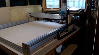
My Workbee style CNC.
Hi everyone. Greetings from New Zealand.
Well, the journey begins…
Let me kick off by saying that although I have five or six years’ experience in 3D printing, I have no practical experience with CNC routers. Building such a machine though has been on my mind for the last few months – certainly since I stumbled upon the Openbuilds website. I found the site a rich resource for ideas, and based on the fact that the Workbee seems quite popular and there are some educational build videos covering several models by the Openbuilds team, I decided to give it a crack. I was never going to try and design a machine from scratch when I knew nothing about them….although I probably will do later on.
After studying the Workbee for a few weeks, I formulated a plan of what I wanted to do. My first consideration was to “prototype” some temporary plates from MDF – the reason being that there were some changes that I planned on making to some of the plates which, hopefully, could be cut in aluminium when the machine was complete. Also, as the build progressed, I expected other changes might take place in the plate designs. Buying a set of aluminium plates that (maybe) would become redundant made no sense. Of course, if the MDF plates won’t stand up then I will have to buy the metal ones. The machine will be used almost entirely on wood and plastic materials plus a few aluminium jobs.
I will post pictures and some videos to clearly illustrate the progress of the build and some of the methods and changes I will be making to the machine. I will also include some Sketchup 3D files etc. This will not be a kit build, I’ll just acquire bits and pieces as I go – importing a kit from overseas is very expensive to ship here with import duties and taxes on top. Anyway, I’m not really a “kit guy” and I guess I like the challenge. Also, there’s probably no point in charting every aspect of my own build, the guys at Openbuilds have some amazing build videos available.
Making the Plates
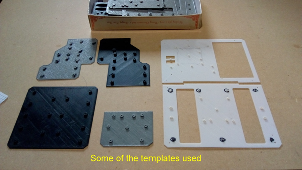
OK, so I began with making some prototypes of all the temporary plates. The pictures can be referenced at this point and the accompanying videos will explain the method I used to create them. My apologies for the distinctly non-professional quality video content, I don’t have the fancy equipment that some people have, just my cellphone in its phone cradle, stuck to the shed window!
Using the cad drawings of the plate set from the OB website, I set about the task of actually making them. My first attempt was to use inkjet printed copies of the plate faces and gum them to the MDF. Having done that though, I looked at the prints on the MDF for a few minutes and decided this wasn’t going to give me the precision they deserved - I didn’t even drill one hole! Everything really has to line up perfectly if one expects to build a precision machine, and trying to find the exact centre of a hole on an inkjet copy was a non-starter for me with my eyesight - I had to come up with something else.
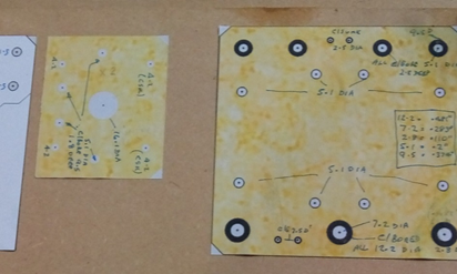
Ink jet “plate labels” on MDF.
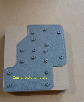
My next thought was to make some sort of 3d printed drill templates and use them to mark out the MDF plates. I had no idea initially of just how successful this would prove to be. One of the templates – a corner plate, can be seen in the picture. Templates were made from PLA, (which I don’t use very often) but was selected because it is more stable and resistant to shrinking. I wouldn’t recommend ABS for instance though it may be ok. Of course, the 3D printer was checked for calibration and the templates measured to check them dimensionally before being used on the MDF.
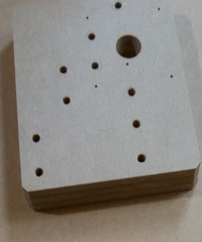
The templates were printed only 1mm thick but with raised holes for the drill to guide through. I saw no benefit in printing the template bodies too thick considering they would be discarded after the job was done and the plastic just wasted. The drill guide holes in the templates are 2mm diameter although as anyone knows who has a 3D printer they will always come out smaller. Before any attempt was made to drill/mark the MDF, the holes in the printed template were “pre-conditioned” with a 1/16th drill I had handy although 2mm would also be fine. This was done so I could feel the drill entering the MDF when I was ready to make a plate – an important precursor as I only wanted to drill down into the board 1 to 2mm.
To reinforce what is explained in the video, the drilling into the MDF was only to be to a depth of 1 to2 mm – one just has to judge it. The reason is, if the hole is drilled right through with the cordless drill there’s a chance it will go offline which may affect the final drilling accuracy on the pillar drill. The entire process can be seen in the pictures and video.
To say that I’m happy with the outcome of the fitting of the plates to the extrusions would, indeed, be an understatement. I was surprised by the accuracy of the fit, especially considering that the 6 MDF plates that have to be screwed into the C beam extrusion ends had to be drilled with a 5mm drill – I had no 5.1mm drill. The MDF gripped the screw pretty firmly (why do wood holes seem to shrink?) so there was zero wiggle room, but they lined up perfectly. In fact, on all the plates, not a single hole out of the 230 or so holes had to be enlarged to fit. It did get me thinking though that maybe I should use this method on other jobs, including maybe, metal? Before fitting the plates, I tapped deeper into the C-beam ends to take 30mm low profile screws. The usual spec, I think, is 15mm screws, meaning only 9mm is available to fit in the extrusion (6mm is taken up in the plate). 15mm is probably fine but I like to give aluminium all the help it needs when threading!
My only concern at that stage was whether the Z axis would be rigid enough with MDF plates. Even if it had aluminium plates fitted, I think it could benefit from being made more rigid – food for thought but I’ll reserve judgement until later. The four corner Y axis plates plus the top and bottom Z axis C beam cover plates and the inner Y plates are 6mm MDF while the X plates, the outer Y plates and the Z plate are 3/8” (9.5mm) thick. That meant using some longer bolts.
Video links:
templates
MDF plates
Lead-screw Mod and nut blocks
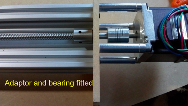
So, some time later and having something beginning to look like a machine, I decided to tackle the next issue – Leadscrews! The 1010 Workbee I am building needs, by necessity, 1040mm leadscrews – just as a 750 model has 790 leadscrews etc. The reason of course is, although the C beam is 1000mm long, the L/Screw has to pass through the back bearing (an extra 6mm) plus the front bearing (another 6mm) and also has to extend into the flexible coupling – hence the need for the extra length. It seems a bit odd though having such a weird dimension. Anyway, I had some 1000mm leadscrews at the back of the shack which I was determined to use.
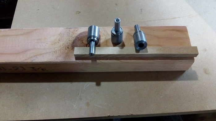
My original thought was to slice 40mm off the X and Y axis C beams. That however, would mean losing 40mm of build envelope along those 2 axes and I would need to get the “square end” precision of a factory cut. After a bit of thought and playing with ideas, the final solution, as can be seen, was to make some adaptors for the screws which effectively lengthen them. The adaptor does not interfere with anything, no motion distance is lost and no changes to the machine are necessary. In fact, the adaptor also serves as a lock collar so only one is needed (at the other end of the L/Screw.) This simple solution standardizes the L/screw requirement at 1000mm. Of course, I had to make the adaptors on my lathe – they need to be pretty accurate after all but I bet our Chinese friends could knock ‘em out for 2 or 3 dollars. I used some 1045 steel which I had plenty of but my preference would be for Stainless which, when I obtain some, will be machined and retrofitted. Thus, both the Y axes and the X are using 1000mm Leadscrews to the same effect as 1040 screws.
Video link:
Leadscrew and adaptor
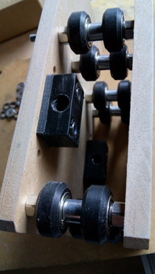
Nut Blocks
The nut blocks…mmm. The current nut blocks appear to be of a design that is used in some other applications which I know nothing of. They have counterbores which a 5mm low-profile screw fits nicely into. The problem is, however, the nut block counterbores are redundant on the Workbee (and others?) and are used differently. They are normally fitted with a small spacer and precision shim between the nut blocks and the plates. The issue is, because of the counterbores, the precision shim or indeed the spacer has only about 0.5mm of metal surrounding the edge of the hole – not a firm foundation for the block at all. I removed the shim and spacer and made some 4mm plastic nut block size spacers to fit the entire back of the block. Much better, a solid foundation for the blocks and they cost virtually nothing.
Drag Chains
Fitting the drag chains was pretty straightforward, although I used my 3D printer to make both the anchor points for the Y axis. Only one 3d print was needed for the X and this was screwed on using the pre-existing holes in the rear X plate. The other end was attached to the 2040 back rail using a screw and T nut. The Oozenest Workbees use a taller anchor on an already tall X axis plate which seemed to gobble up some of the drag chain length vertically hence the reason I decided on a different design which lowered the chain to give back some length – no problem if you have a long chain of course!
Motor Mounting
To fit the X, Y and Z motors onto the MDF plates I needed to get a bit creative. Tapping into MDF might work but it’s hardly desirable. The pics and videos reveal what was required to enable screw
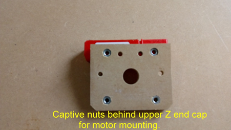
and nut fixing. Basically, what I needed was a pocket of about nut depth and 8mm in diameter – a perfect size to draw the nut into the wood, grip it, and be held firmly in place. Two of these nuts are hidden when the plates are attached to the ends of the C beam but, amazingly, the C Beam traps the edges of the nuts to stop them being pushed out while allowing the screw itself to engage right through the nut. Standard 60mm screws were used.
Base extrusions
Well, having droned on earlier about not cutting the C beams, I then, of course, realised that I needed to cut the pesky base extrusions to fit inside the frame! Oh well, at least those parts are hidden. I bought an aluminium-cutting saw blade for my cheapo saw bench and used a cross cut sled to slice up the extrusions. It’s a good idea to clamp them to the front guide to stop them moving and to counteract the cutting forces. They came out decent enough. They do differ from the stock Workbee though due to the fact that I used 2060 extrusions for the base, fitted upright to gain more rigidity – one at each end (replacing the Workbee 2040’s) and 4 from front to back, therefore six total.
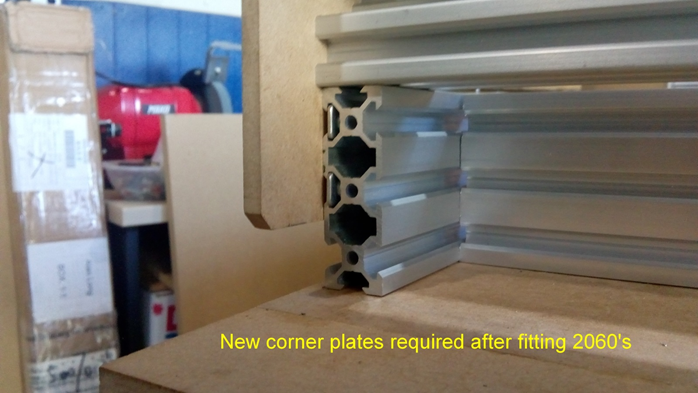
However, having 20mm taller rails meant that the corner plates were now sat up by 20mm from the table – they would still work the same but I figured that as I was using temporary MDF plates anyway and (as detailed earlier) they are easy to make using my template method, I just knocked up another 3D printed template, 20mm taller, and made 4 new plates. I incorporated two more screw holes for the wider rail giving 6 fastening points instead of the original 4 on each corner plate which should yield more rigidity – good job I didn’t have aluminium plates already but that’s a good example of why I started with temporary ones.
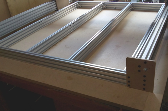
New corner plates done.
Wiring and Electronics
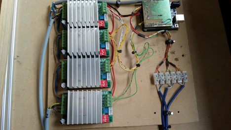
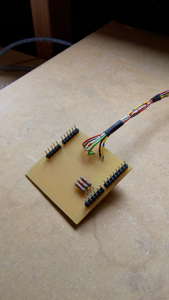
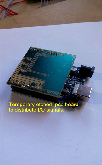
For the electronics, I have gone with Nema 23’s @ 270 oz-in (I’m guessing 170 oz would be plenty enough but I’m thinking ahead in case I need more power for a future build). I had a couple of Arduino UNO’s, so no reason not to give one of them some meaningful employment. Motor drivers are un-cased TB6600’s which have a fanciful rating of 4 to 5 amps – I’ll be happy if they deliver the 3 amps the motors require. I knocked up a PCB drawing of an Arduino shield to sit on the UNO – this to provide a means of feeding all the wiring to the drivers, adding pull-up resistors for the limit switch connections and a 5 volt/ground connection. I intend to re-design the shield to accommodate a plug and socket connection. The power supply is set to deliver 32v which should be fine.
The motor wires have been fitted with aviation plugs which I’ve had in my spares box for several years but never used. For the Y axis motor connections, I printed a couple of brackets which attach to the end plates using 1 of the 2 holes already there – the aviation plugs are mounted to the brackets.
The Z motor connector is plugged into a printed receptacle attached to the X rear plate which houses the aviation plug, while the X motor is wired through the Y outer plate. See pics to see what I mean.
Regarding the limit switches….
On my old 3D printer I installed miniature, glass encapsulated, reed switches during construction which have proved to be very accurate and reliable in use. I am considering them for my CNC build. They are completely immune to dust etc and moisture resistant, and in 6 years of use I have never had a fault or replaced one. For now though, I have regular micro-switches on X and Y, and a reed switch on Z.
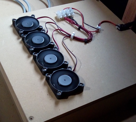
While agonising over what router (or spindle) to purchase I ran some G-code of the openbuilds logo and a few others to test out the motion. I used a pencil for the OB logo and all seemed fine. The motor drivers heated up to what I would call “operating temp”, but cooling fans will definitely be added when I’ve finished testing and they get to do some real work!
Z axis
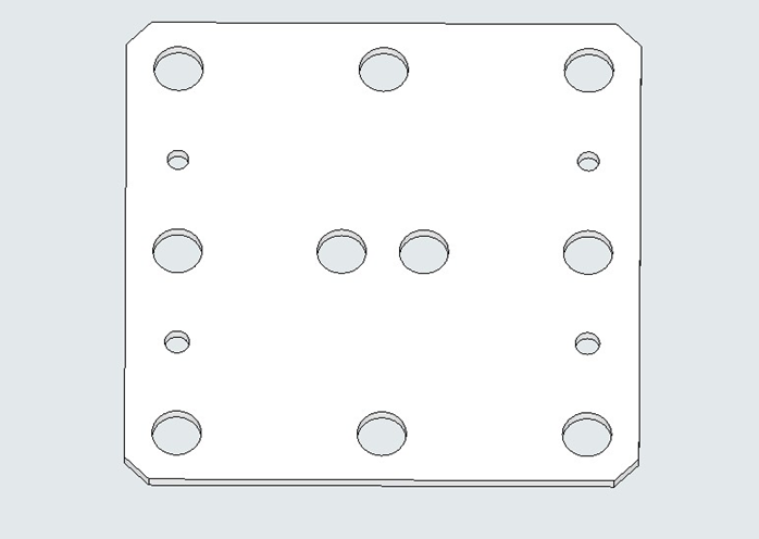
As I mentioned previously, I was a little concerned about how the “Z” MDF plate would stand up. Well, it didn’t really. Once I had it assembled to the X plate I realised that even with thicker plates it was too easy to stress the plate – that is, the roller shafts could move/stress the MDF shaft holes by pulling on the Z C-beam. At this point, I realised that I would have to make an aluminium plate to overcome the problem. Fortunately, my “template system” worked fine on metal though I adjusted the procedure slightly. Of course, having had success making it, I just had to do the X plates also – well, I really wanted metal to metal and not metal to MDF. The only setback was the need to have counterbored holes in the back of the Z and the front of the X plates so they could sandwich together (to accommodate screw heads). I do not possess a tool to do that in metal. Countersinking was an option but I eventually decided on an aluminium spacer with clearance holes for the low profile screws. A temporary solution until I make aluminium plates on the machine.
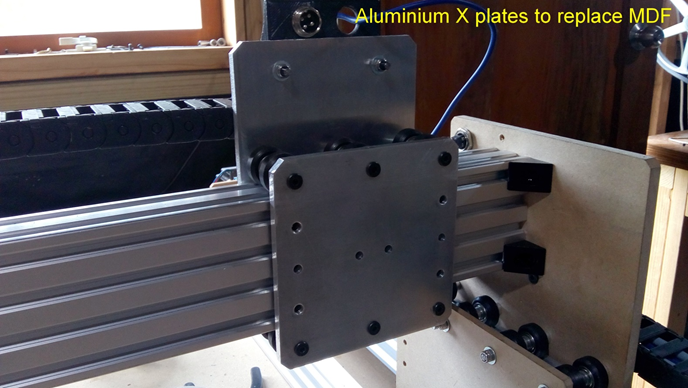
Front view of the aluminium X plate clearly showing the 4 tapped holes for mounting the Z actuator assembly (thanks to MetalGuru).
5mm spacer sandwiched between front of X plate and Z plate
Video link:
X and Z aluminium plates
.
Spoilboard
Generally, the spoilboard, from what I’ve seen, is mounted directly to the base aluminium frame. That’s where mine is fitted but I’ve decided to utilize that board as a baseboard so it becomes part of the frame structure only. I will then fit a second board on top to serve as the spoilboard. I like the idea of T–tracks that some makers have implemented so that’s what I’ll do here when I source some tracks. Doing this will reduce the usable “Z” height but as I am using temporary MDF plates, it really doesn’t matter – they can be re-designed to be a bit taller.
The following day…
Since that previous comment and not knowing when I’m likely to have some T-track in my possession, I figured I would look into machining some T-tracks directly into my spoil board like many others have done. I have plenty of MDF so I wasn’t too worried about the outcome. Having done all the measurements and calculations and drawn it up in Sketchup, all that was needed was to import it into V-carve and create a toolpath. I then discovered that I didn’t have a darned slot cutter! Not wanting to buy one at this stage, I abandoned the idea and retreated to the man-cave for a beer.
Later… Well, I figured out another way of doing it. This would be the same effective T-track but no slot cutter needed. Also, when spoil-board replacement was necessary, there was no T-track machining required (as it would be for regular t-slot boards) –they just needed cutting to size. The biggest problem I see with T-tracks cut into MDF is that when they are surfaced (or resurfaced), the top “overhangs” that the anchor bolts pull up against get thin pretty quickly. Anyway, enough of the waffle, here’s what eventuated.
Below is an idea for an MDF T-tracked spoil-board – I still like aluminium extrusions for the track but I’m beginning to warm to the idea of "t-tracked" MDF at least for the time being (or is it non-T tracked T track?) As can be seen below, the baseboard, which as I mentioned above, is part of the frame structure has several rabbets (channels) cut front to back within the machining envelope of the CNC. Easy Peasy! The spoil boards are made up of equal sections of plain, rectangular MDF routed to size – no other machining required. The idea is that the edges of the spoil-boards become the “overhangs” of the T-track. Summing up then, the baseboard milling is a once only job and the only maintenance needed is replacing spoil-board(s) when worn down through surfacing. I will be using sunken bolts in the top surface - they need to be firmly attached as you would with any other set-up. The drawings shown are Workbee 1010 size.
I have not started this job yet but will shortly.
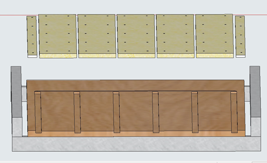
Exploded view showing the rabbeted baseboard.
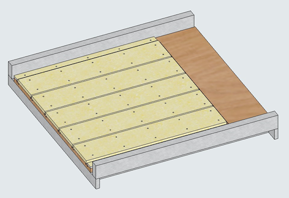
Overall view.
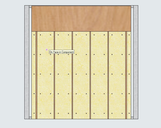
Top down view.
The channels in the baseboard are 8 mm deep. The spoil-boards have their edges overhanging the slots by 8mm. The gaps between the spoil boards are 8mm wide. Thus, an 8mm wide bolt secured to a suitably sized flat brass or steel block will make up the T bolts.The rabbets shown in the baseboard are 24mm wide but they could be different. Note that the 2 narrow pieces far left and far right (Wood or aluminium) are not part of the spoil board, they are there for clamping purposes. When surfacing, the entire area of the spoil board is machined thus giving a total wall to wall flat base. However, there will be a slightly raised surface on the left and right edges (where the narrow boards or aluminium strips are fitted) which would render the slot slightly high on the left and right sides.This is unlikely to impact on the clamping due to the minimal base surfacing that's needed but if necessary, a fillet could be fitted under the side strips as shown (height exaggerated for clarity) . These edge strips shouldn't really need replacing and the baseboard shouldn't need surfacing again so its a one-off job. The actual thickness of these side strips is determined by the amount of re-surfacing the spoilboards will endure. For example, if the top edges of the bolts holding down the spoilboards are 8mm below the spoil board surface, then the side strips can be on the same plane (but not really higher). That means a full size board can be laid flat right up to the far left edge (or right edge) of the side strip if needed. Cutting however can only occur within the X axis envelope.
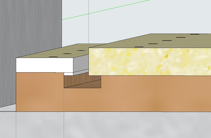
Fillet attached under left side. (If needed)
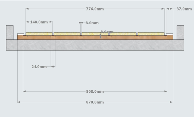
Dimensions of baseboard and spoilboard. (Standard 1010 Workbee)
I will first surface the baseboard which shouldn’t really need much of a cut – this will leave a slightly raised shoulder either side of the baseboard which is where the edge strips will sit. The surfacing cut will be 808mm wide which is the distance between the leftmost edge of the left rabbeted slot and the rightmost edge of the right side rabbeted slot. My intention is to fit a single sheet of 776mm Wide MDF (well, probably 780 wide to allow for trimming the edges) to the baseboard and then, after fixing, cut 8mm wide slots for the T bolts, front to back, milled by the machine thus guaranteeing perfect separation to create the “T” track. I will be building this design shortly - I’ll report back in due course. A Sketchup drawing and DXF file for tool-pathing the baseboard rabbets will be uploaded with the build, (If anyone is interested).
Video link:
Channels and Y plates
V-wheels and axis motion
(Included in above video). The workbee has 8 fixed V-wheels on top and 6 adjustable wheels on the bottom on both ends of the Y axis. This means the gantry load can be spread between 14 wheels which can’t be a bad thing. I did however wonder if equal pressure was being applied to all four pairs of wheels or were some just going along for the ride?
Well, that’s what I found – some were just not doing their job. It’s obviously quite difficult to get perfect balance between all 4 in a row of rollers so when I design my aluminium plates, one of the considerations will be for a 3 wheel configuration (3 pairs) of the upper part of the “Y” plates, but, not only having 3 pairs of fixed wheels instead of 4 but also changing the role of the inner wheels to be adjustable, i.e. the 2 outer wheels (in each row), are fixed and non-adjustable while the centre wheel has an eccentric – thus the outer wheels set the position of the assembly squarely to the axis while the inner wheels can be adjusted to just mate with the C beam track to get full engagement of all the wheels. Further, because of the extreme difficulty in adjusting the wheels after the machine is assembled or indeed after it’s been running a while, I think that swapping the roles of the upper and lower wheels might be worthwhile. In other words, the “fixed” wheels currently riding on top will be at the bottom, while the 3 adjustable wheels will be up top where they are easy to access. At the moment, this is just an idea. In this reversed position, the lower rollers would then set the position of the assembly squarely to the axis.
The “X” axis is already a 3 wheel design so the only change I would make there would be to implement adjustable centre wheels as above. The “Z” axis is similar to the “X” except it has single wheels on each side - something I'll be taking a long hard look at when I get time.
Router
I have gone with the Makita router for my machine. The De Walt would have been nice but seems to be impossible to buy here. The Makita though is supplied with only 1 collet – a 0.25”. Because that limits the range of cutters I can use, I decided to make some more of different sizes on my lathe. They turned out very well with little runout, maybe 0.0004” (0.01 mm) so happy with that. I will upload the dimensions for others to make if they wish.I have already made a 1/8" collet, a 4mm collet and a 6mm. I have not yet made an 8mm collet - not sure if I'll need one.
..still to come.
machining spoil board, wiring diagrams, files and drawings, aluminium plates plus any other changes.
Workbee "style" 1010 cnc
Build in 'CNC ROUTER BUILDS' published by Christian James, Feb 12, 2019.
This build is based on the Workbee 1010 CNC. It is not a kit build and is much the same as the original but with some significant changes made here and there as the build progresses.
-
-
Build Author Christian James, Find all builds by Christian James
-
- Loading...
-
Build Details
- Build License:
-
- CC - Creative Commons Public Domain (CCO 1+)
Reason for this Build
A natural progression from a 3d printer and another supertool to add to the shop.Inspired by
Openbuilds!


