WorkBee 750 x 750 from Ooznest.
You'll have to bare with me here as this is my fist foray into the CNC world. I first began by looking into designing and building my own cnc machine, after much research and the pros & cons of a DIY build as opposed to a readily available kit, it quickly became apparent that a full kit would be the best option. In reality, there isn't much of a saving, if you decide on purchasing all the necessary parts from various sources the costs increase. The distinct advantage is the support you'll also get if you purchase all the necessary parts ( or kit ) from one supplier.
Reading the members builds section on this forum I eventually found www.oosnest.co.uk. As I'm based in France this was my only option .................... I'm certainly not paying French money for a cnc machine ! This sort of kit is really expensive in France, and the UK is only a stones throw from where I am.
I'll try and give future buyers of the WorkBee valuable tips I've learned while assembling my machine, hopefully some people will find it interesting. And I'll also give you my honest opinion on the WorkBee kit and how easy it is to assemble and operate. But don't forget, I'm learning this also so there may be errors !
The complete kit arrived very well packaged ( 2 boxes ), one slightly damaged box, but that's the shippers for you ! However, the contents were very well wrapped that everything was in order >>
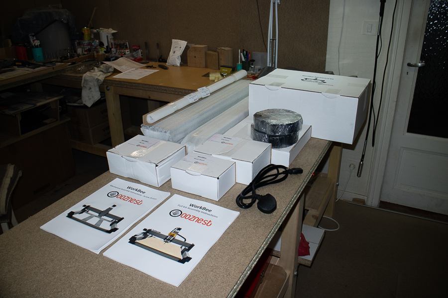
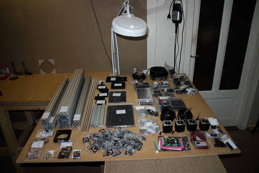
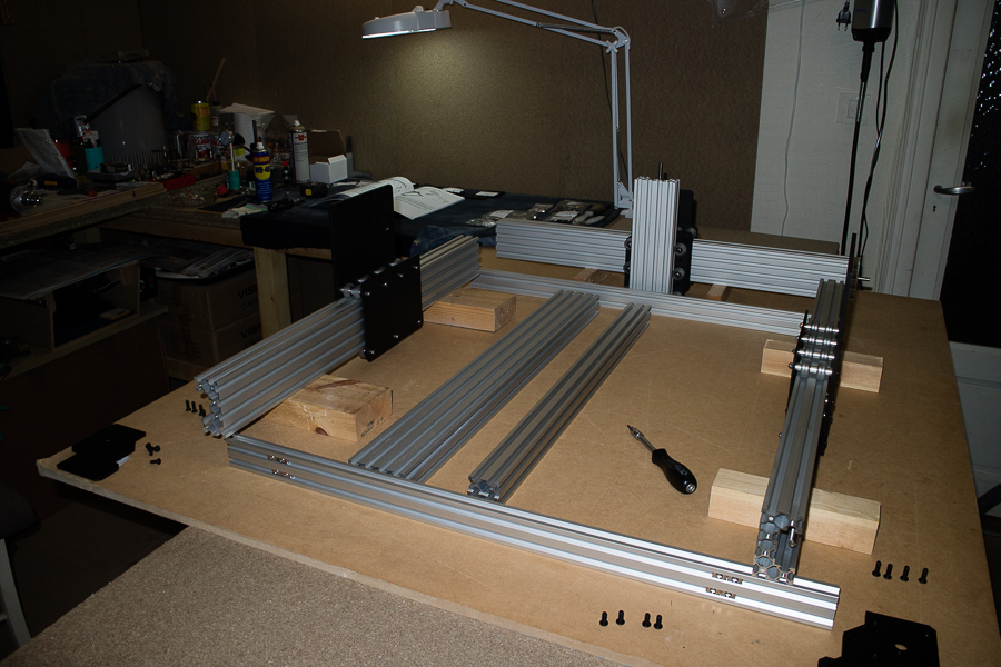
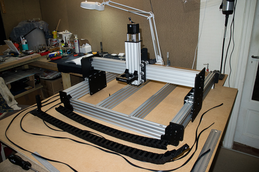
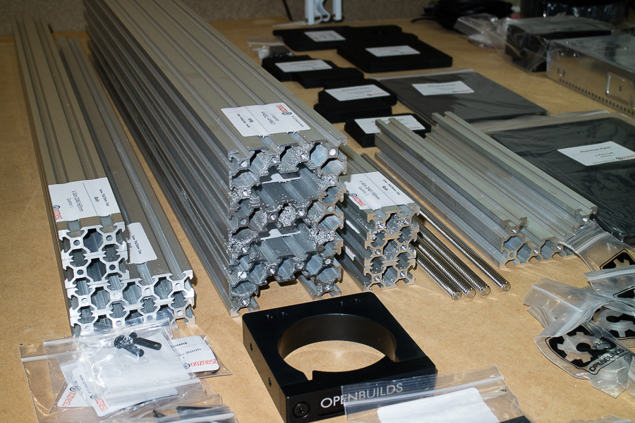
After unpacking everything ( that took me almost an hour ! ) I did a visual check of everything. As you can see, there's a fair bit to it. >>
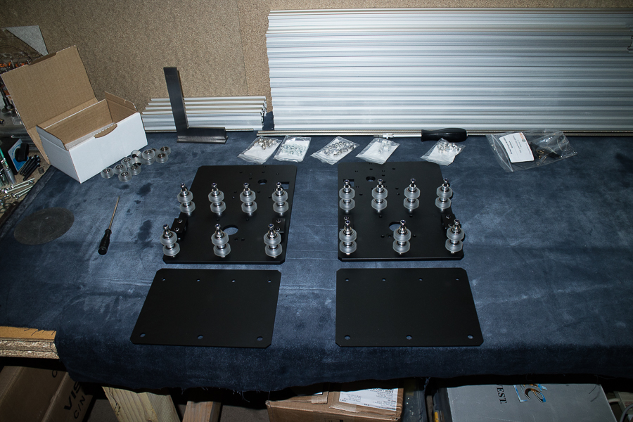
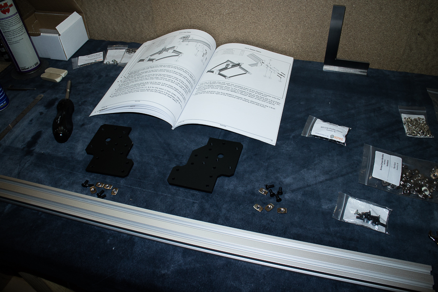
As can be seen from the first image, the kit comes with 2 very well laid out assembly manuals. So I began by assembling the wheels as per the instructions >>
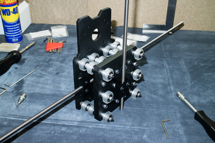
Then installing the wheels to the Y plates. So far everything looks pretty straight forward >>
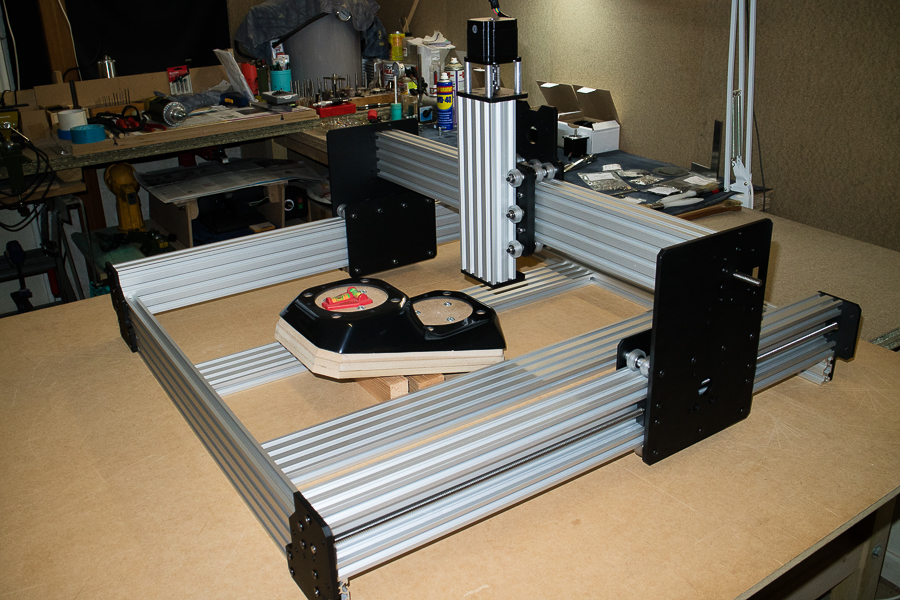
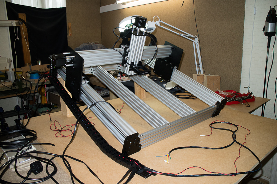
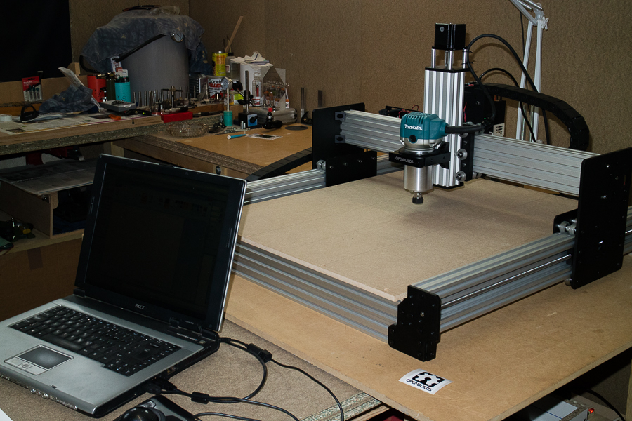
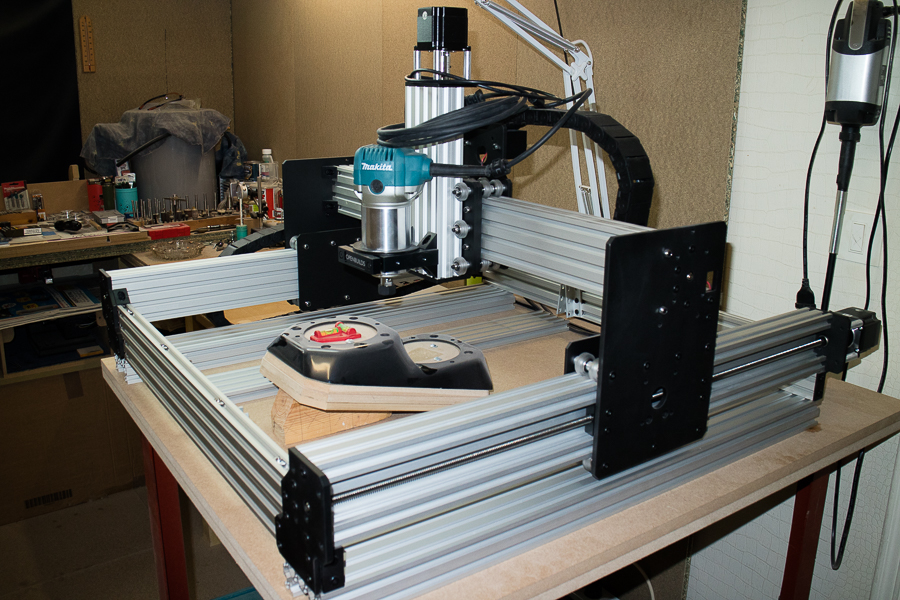
I had planned on using an old table that I have, but I was quite taken aback by the shear size of this machine, it may only be a 750mm x 750mm screw driven machine, but you do need something a little larger to accommodate it. In the coming weeks I will have to build a proper torsion type workbench for it >>
The 'Ikea' style assembly manual with all the step-by-step diagrams with all the numbered parts, is very easy to follow, even a novice such as myself didn't have any problems following it >>
I did have a couple of issues however .............. the ACMC nut blocks in my kit were very very tight, to the point that I couldn't even turn them. A quick phone call to Ryan at Ooznest, and the replacement parts were FedEx'd instantly ! I received them the following dayGreat service Ryan ....... thank you so much ! A service I doubt I would of had, had I of bought my parts from China ! >>
The assembly' coming along nicely now. I found it very helpful to support various assemblies with box's, blocks of wood or what ever you have laying about, they help to support the weight as some of these parts can be quite heavy while you're trying to screw them together >>
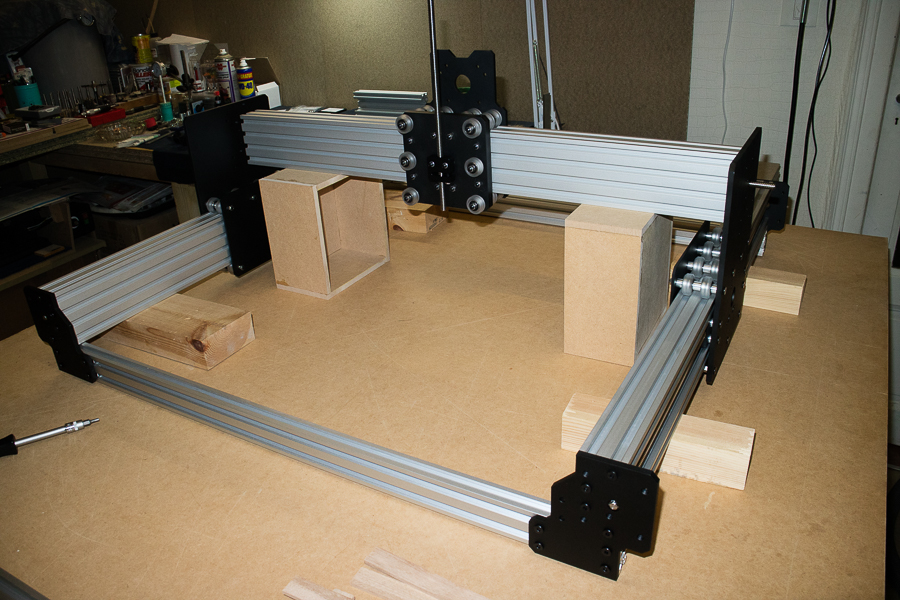
I also veered from the assembly manual in a few places as I found certain things were easier to do my way, so I would build a 'sub-assembly' them assemble that to the rest of the machine. You do what suits you basically >>
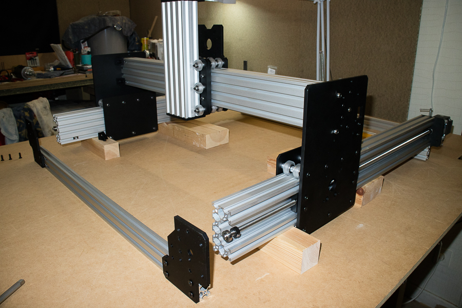
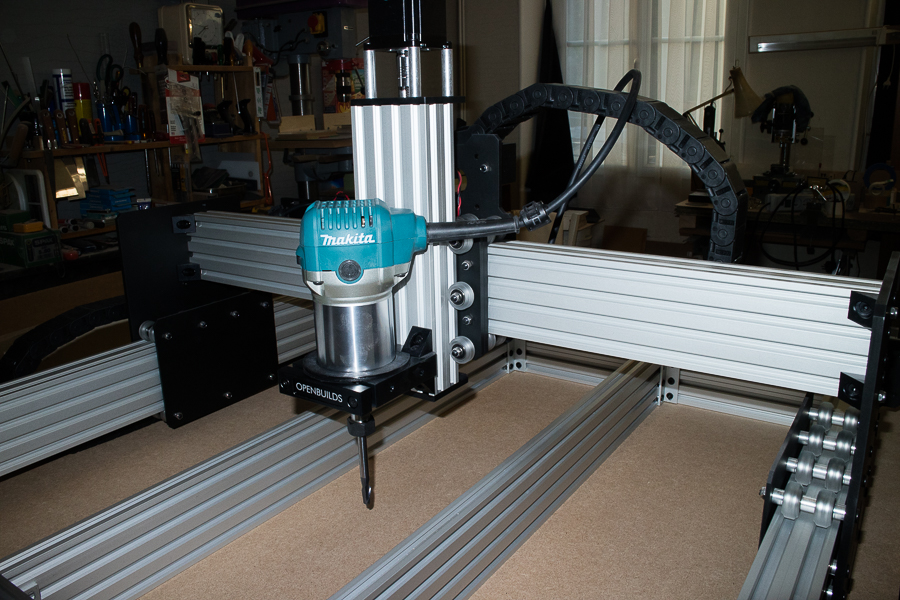
A great innovation that the WorkBee has is the 'Dual height' method. You can basically have your spoilboard set high or low ( as in the image below ). In this set up you would increase your cut depth >>
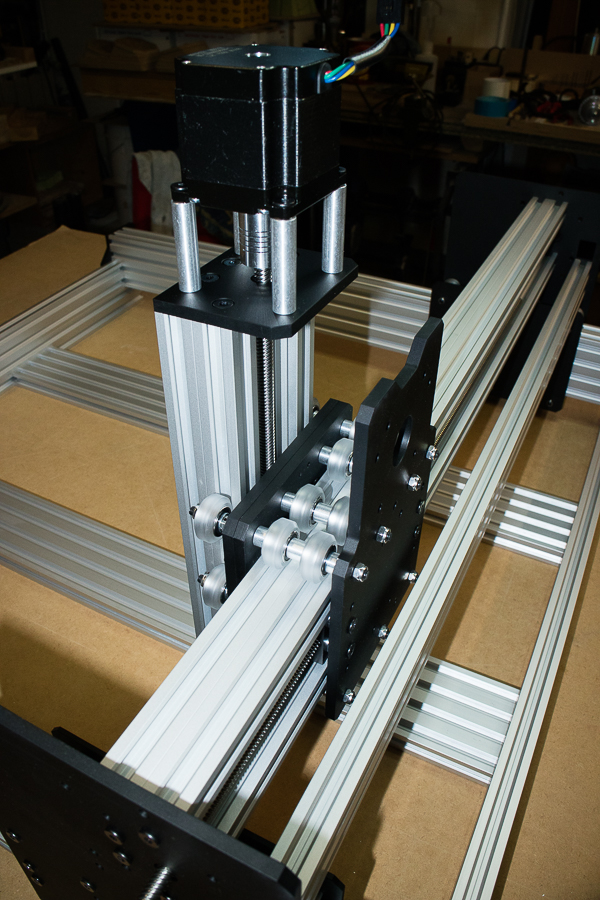
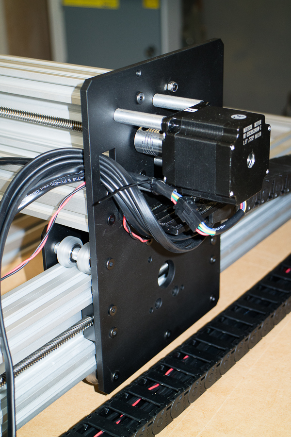
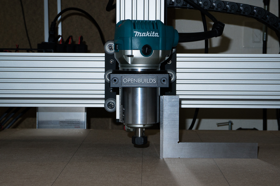
A close-up of the Z axis and NEMA23 stepper motor installed onto the X Gantry .............. I do love precision stuff !
As I design and fabricate custom quad headlights, I needed a machine that's capable of profiling, cutting all the holes in the headlight mounting brackets, the material I mostly use is 3mm ABS so there's no great stresses involved as there would be with machining aluminium for example. But they do have to be millimetre precise >>
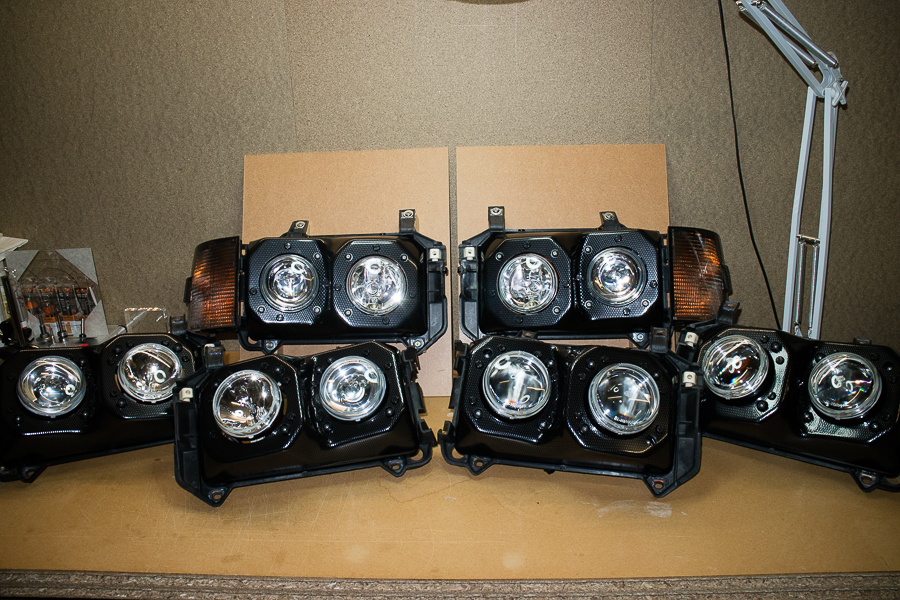
Up until now, I have been cutting ( profiling ) all the headlight unit mounting holes by hand >>
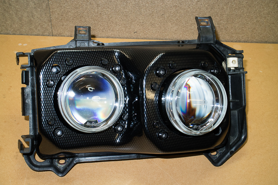
So this is how I intend in using my new cnc ......... The headlight mounting bracket is quite an awkward shape, but I can take advantage of the WorkBee's dual set up, and mount my brackets 'under' the spoilboard with just the top part exposed. More on that at a later date >>
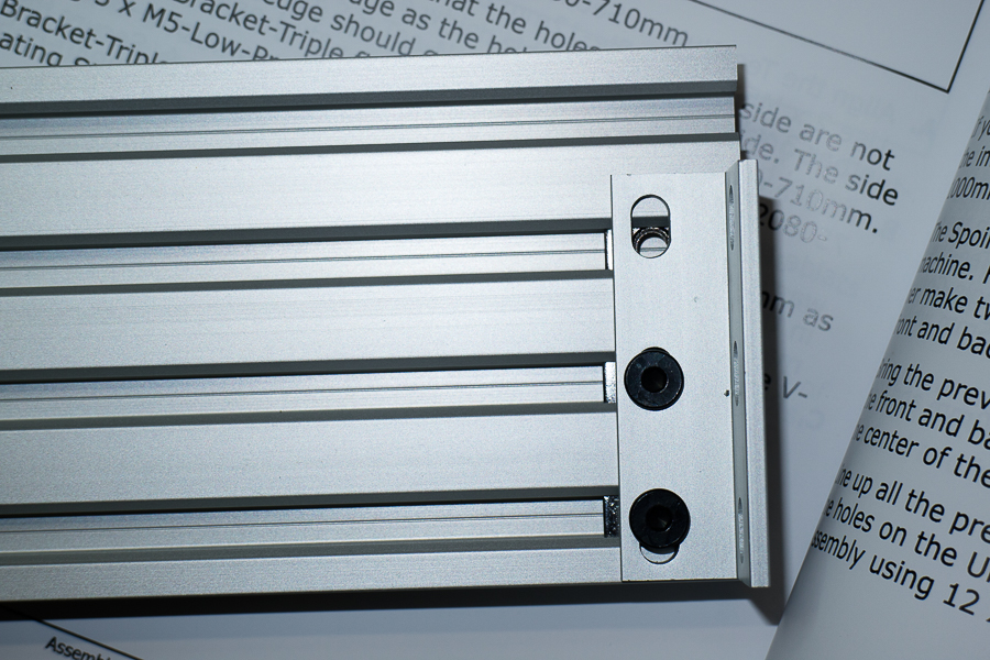
Another issue I'm having is the 'Universal-Bracket-Triple', I can't for the life of me figure why I can't get the third screw in, it just won't line up ! Anyone else encountered this ? Did you simply file the hole a little bigger ? For the time being I'm having to only use the two bottom holes >>
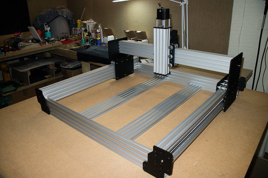
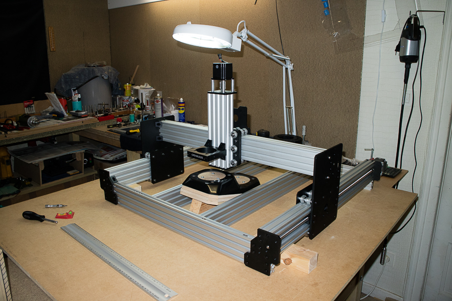
For the time being I've chosen to assemble my WorkBee as 'Method 1', whereas the 'spoilerboard-extrusion-supports' are installed vertically. As I can still take advantage of the space inside the WorkBee, and the extrusions help to hold my part in place >>
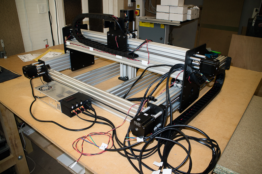
Once the 'mechanical' side of things has been fully completed, you move onto the second assembly manual that covers the cabling, wiring and the final installation of the limit switches, the controller board and the power supply. The first step is to begin assembling the drag chains and running the cables. I found it helped to label the cables at their ends when running the cables, as with so many cables it soon becomes quite confusing which is which >>
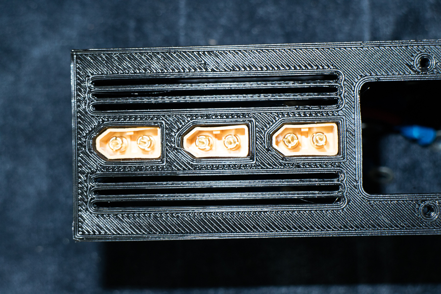
Also, at this point I think it's worth mentioning that if you insert the XT60 male connectors into the 3D printed power supply cover first, as instructed in the assembly manual, you may encounter a problem as I did. You can see in the photo below that the XT60 male connector is now deformed. I found it easier to connect the two ends of the power cables first, then push the XT60 connectors into their slots >>
Another thing to note, all the wires for connecting to the power supply are rather short. Makes the assembly a little awkward, doable ! but very fiddly. They could do with being a centimetre or two longer >>
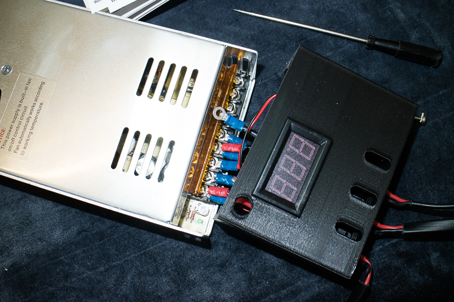
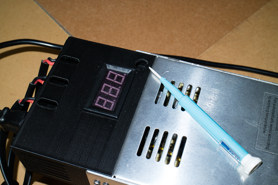
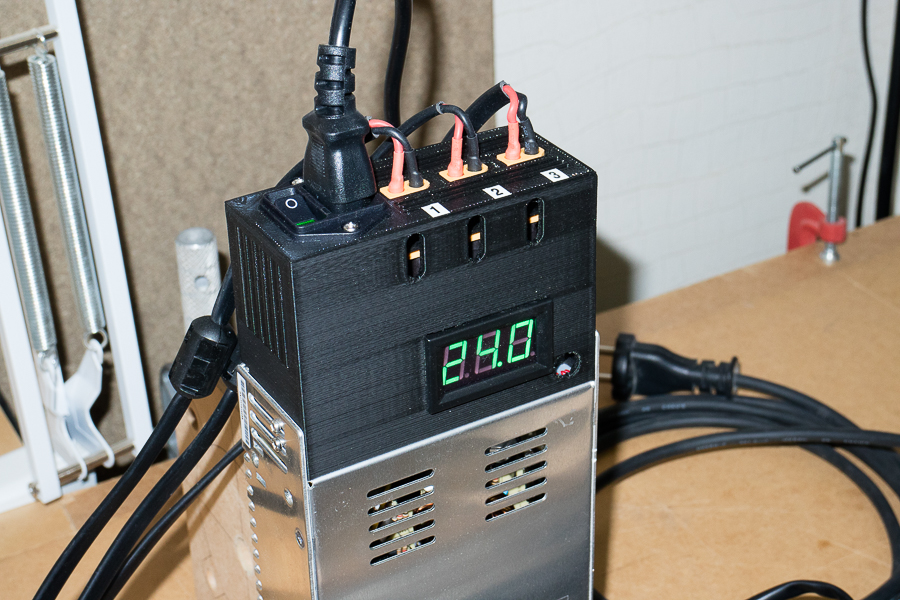
The manual specifies to test the power supply is actually supplying 24 volts ( it can be 'tweaked' ), as you can see from the image below, mine is reading 24.3v is it absolutely crucial that the power supply reads 24.0 volt ? would I risk damaging my X-Pro CNC controller board otherwise ? >>

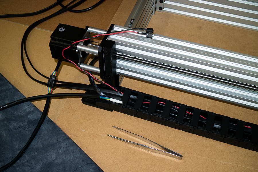
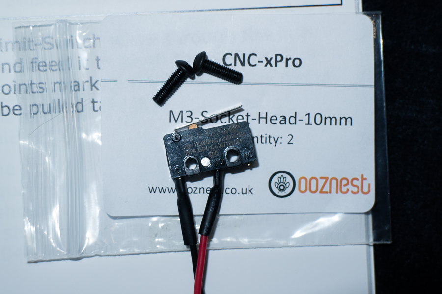
I then set about installing the limit switches and running the wiring down the drag chains. Helpful hint for any would be owners of the WorkBee ............... a little electrical tape on the ends of the wires, and a pair of tweezers to help feed it through >>
It was only at this point that I realised that the limit switch mounting holes were too small, I found only one hole was large enough to accommodate the 3mm screw supplied. I was a little nervous about drilling a larger hole, as the switch looks as though it's made of 'bakerlite' ! so I opted for a safer option and filed a larger hole using a round needle nose file >>
It was then I suddenly realised that I had made a very big mistake !
Now this is the view I have of it's location ! .......... I tried for hours to get that tiny little switch in there. I'm no contortionist that's for sure>>
Drastic measures were required, so I was resorted to doing this !Yeah, I know, laugh all you want, but I think there's a lesson to be learned here .......................... READ the frig'n manual dude ! and make sure you understand it.
How unprofessional
All is well again ! ................ and here's were it goes

And now we get to the electricery. Should be straight forward though as I've labelled up all my cables >>
As tidy as I can get them I think >>
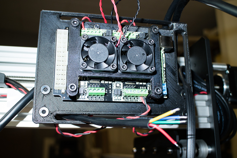
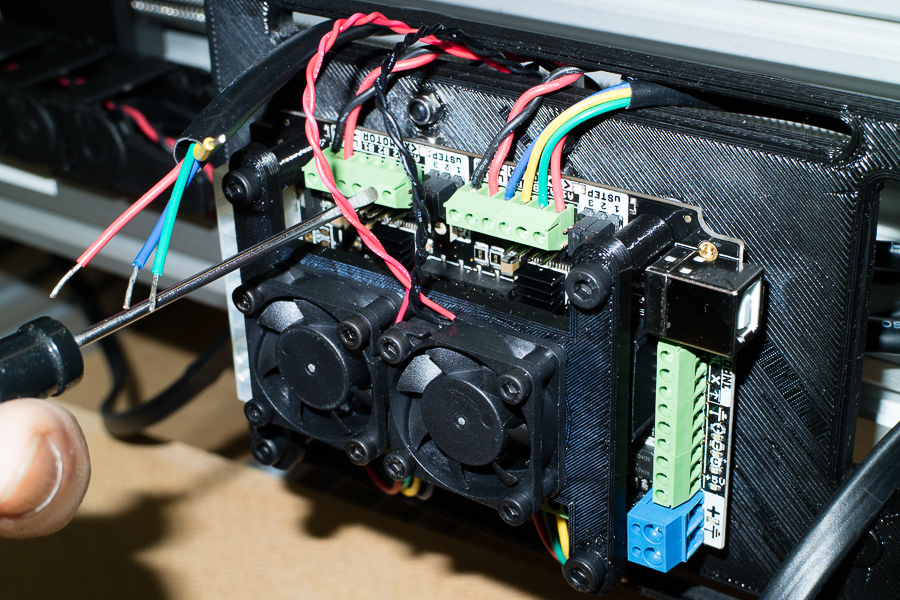
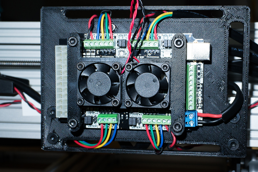
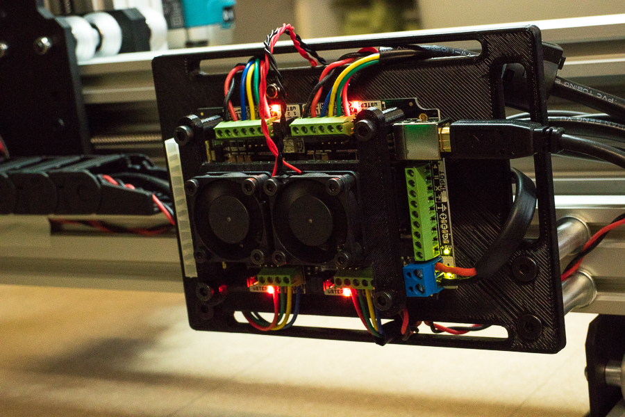
Next up, preparing the X-Pro CNC controller board and mounting the fans >>
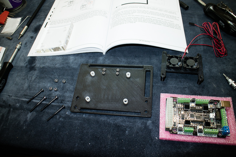
Easy peasy ! .................. hopefully I have the fans directed downward, they should push cool air onto the board to keep the chips cool >>
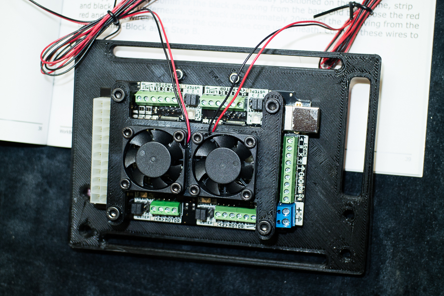
Connecting one of the 24 volt power cable to the dual cooling fans. I decided to use crimp on connectors here as I had some in stock >>
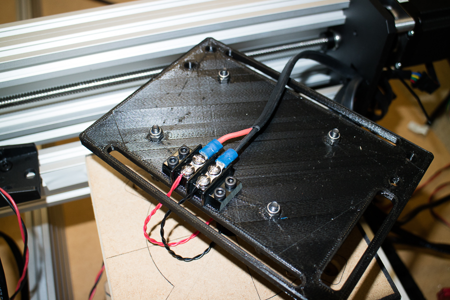
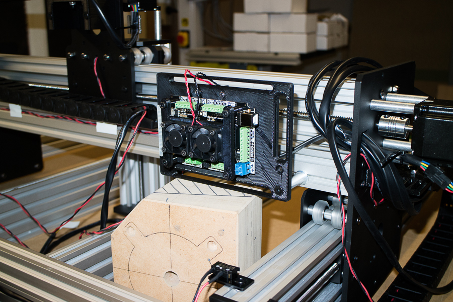
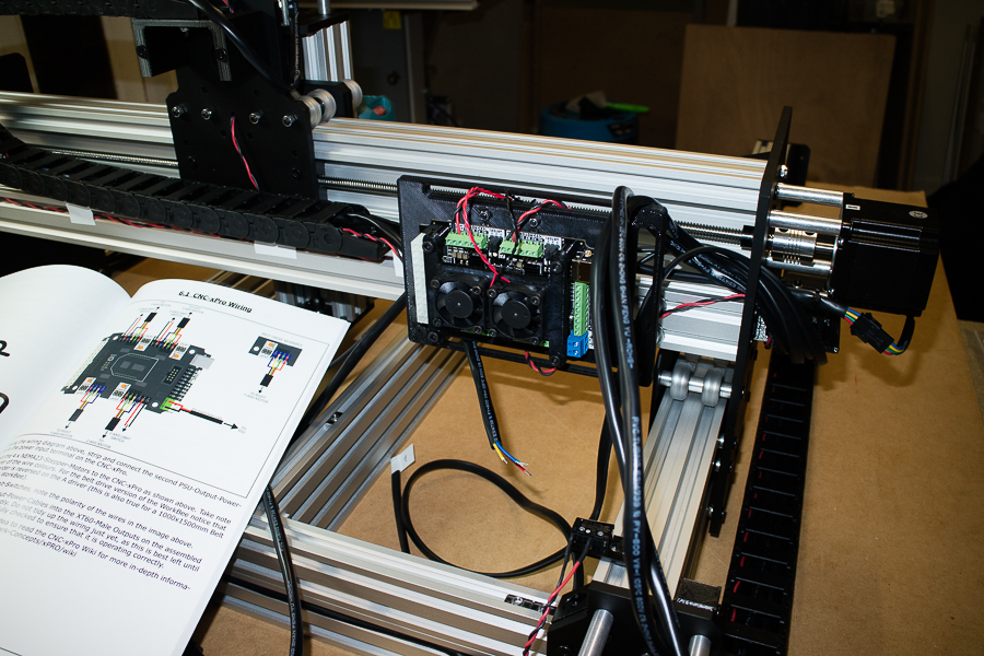
And then mount that assembly onto the X gantry, a little support helped immensely while screwing it in place >>
You don't have to be an electronics engineer to accomplish this task, the directions in the manual are very clear, Ooznest even supply the tiny ceramic screw driver that's needed >>
Well folks, that's as far as I got today ..................... overall, a very pleasurable experience, lessons learned ( many more to come no doubt ). Tomorrow I will complete the wiring, and hopefully run some code
And just on a final note, I also just received my 3D printed 65mm shim ( also from Ooznest ) many thanks Ryan
Hope you all enjoyed my little write-up, and how I did my assembly of the screw driven WorkBee,
My honest assessment of the WorkBee Full Kit .................... can't fault it thus far. Would I recommend one ? absolutely
Edited: 9th February 2018
Hi all, Glad everyone is enjoying the build thus far ................. as for me, the best fun I've had while still wearing all my clothes !
So I'll carry on ..........................
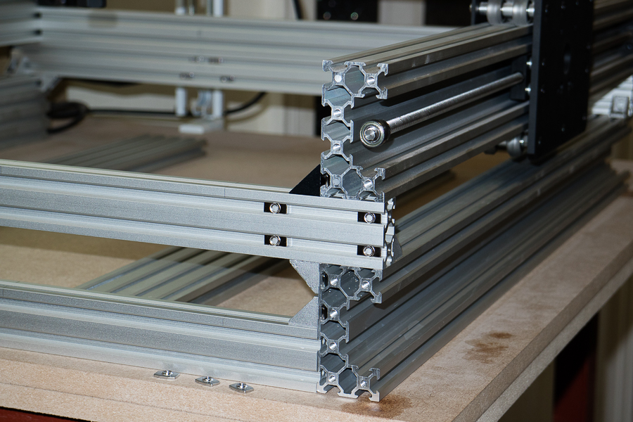
A couple of things I neglected to mention, firstly, one of the main advantages of ordering a full kit over a custom DIY build is, I didn't want to have to struggle with cutting and tapping the aluminium extrusions. You would need an extremely accurate chop saw to get decent clean cuts that are perfectly square, and sometimes tapping holes to the correct thread isn't always as straight forward as it seems. If you don't possess that sort of tooling Ooznest offer a cutting and tapping service anyway, well worth the little extra if you choose the custom size option. This is how the kit looked before I began assembling the sections.
Everything cut and tapped as it should be, I doubt that I would of got them as neat as that !
Also, you may of seen in one of the pictures a can of WD40, I did not use that to spray on the V-Wheels to aid with the running of the machine, the WD40 was only used to clean the residue left by the stickers on the aluminium extrusions. If you need to lubricate any moving parts only use Silicone spray. I just lubricated the ACMC lead screws >>
OK, so I'll carry on from where I left off last time .............. finalising the wiring. After struggling for quite a while inserting the stepper motor wires into the tiny connectors on the controller board, as the holes are rather small and the multi strand wires tend to fray easily, I decided to solder the ends of the wires. Don't put too much solder on them though, as you'll never get them in the holes >>
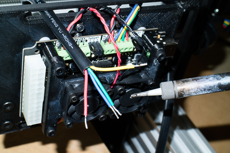
I would also definitely recommend on using a small flat blade screw driver, like watch makers screw drivers to tighten the connectors up, as I managed to crack the tip off my Ceramic screw driver that came with the kit
And here's where it's really needed .............. You wouldn't want to poke a metal screw driver down that little hole to adjust the 24 volt voltages ! That power supply may need a little tweaking as you'll see later. It may also be needed to adjust the pots on the controller board that adjusts the voltage to the stepper motors. I first tried to fix the broken end of mine by sanding it flat, then I tried to file it ............. nothing touches it ! it's amazingly tough stuff. Looks like I'll have to get my grinder out ! So, try not to damage it. >>
OK, so that's all the wiring done .................. nice and neat just as I like it
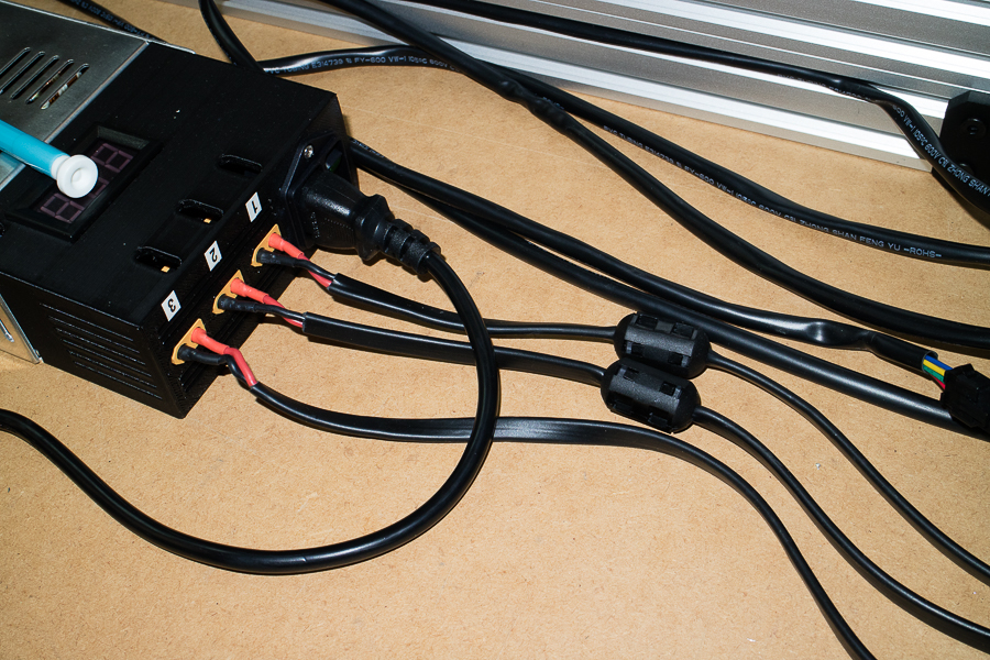
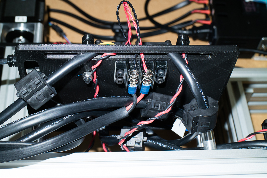
Next up was to put the 'Ferrites' on. There are two types of ferrites to install, a couple on the power cables and one on each of the motor wires. The manual didn't actually specify at which end !? I don't really know how effective a ferrite is depending on it's location
You really do have to clamp down on these, as the ferrites are round and the cables are flat, but they work quite well >>
And these are the locations of the ferrites for the stepper motors. If I have these incorrect, could somebody let me know please >>
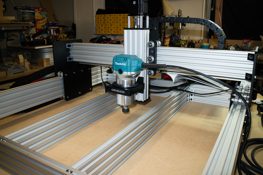
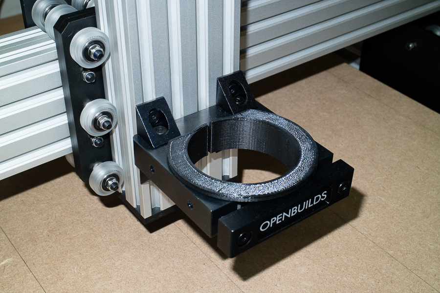
The other thing that I didn't show you guys was, the 65mm 3D printed shim that Ryan at Ooznest supplied me. Nice ! now I can use my Makita RT0700 router without the need of bodging something up
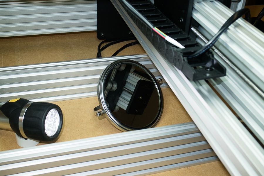
I won't be using my router just yet, but that's no reason to not check alignment. As the manual suggests, use a marker pen for your first trials runs, as I will be doing >>
At this point I was getting ready to power everything up, but first I had to set my power supply to read exactly 24 volts, the ceramic screw driver is made for this purpose ! You'll also notice here that I have numbered my power outlets, #1 through to #3 ......... what I didn't know at the time was, only two power leads are needed. The third is a spare !
It lives !
Now I'm ready to hook up my newly built CNC WorkBee to my computer

Here's where things went slightly awry ! ............. Firstly, I made a poor choice of wanting to use an old laptop
So I installed Windows 7 Professional on the laptop ( I'm also running Windows 7 Ultimate on my desktop PC ), but running Windows 7 on a laptop that has a mere Gig of RAM, forget it, don't even go there folks. Get a decent PC would be my recommendation. You may think that running mere G-Code is a simple thing, but you also need things like JAVA to run 'Universal GCode Sender', and a bunch of other stuff >>
Following the excellent guidelines outlined in the WorkBee Manual, I did mange to do a little something >>
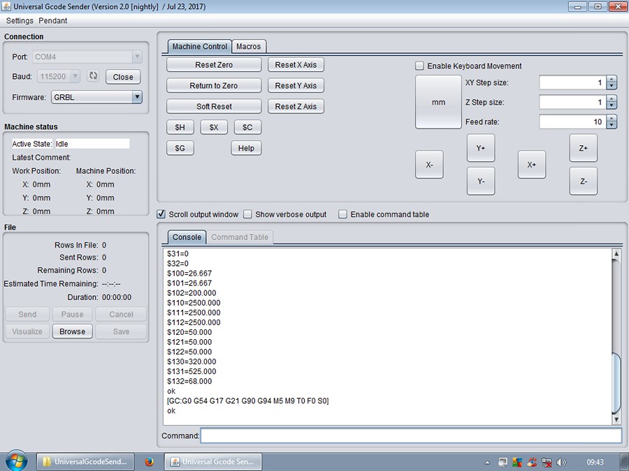
I was surprised that I had to change quite a few setting though. But that's understandable, as not two cnc will have the same dimensions >>
I kind of suspected that I would get stuck on some of these settings, having never seen a CNC machine in operation. Following the manual, I was wonder why it was 'Homing' top right of my machine !? It then dawned on me that it was actually locating the limit switches !
Anyway guys, this is where I've got to ................... X, Y and Z jog correctly, I can 'Home' the machine, I've 'reset' or 'set' the correct 'Home' position, but why is that 'Machine Position' in the 'Machine Status' not resetting to '0' ?
Have I missed something ? >>
Not very impressive I grant you, but it's moving under it's own steam, so far so good, and I'm well happy
I'll post up my current UGS settings later, hopefully somebody can point me in the right direction. Right now, I'm off to read the Wiki
********************************************
WorkBee CNC build Update: 16th February 2018
Hi folks,
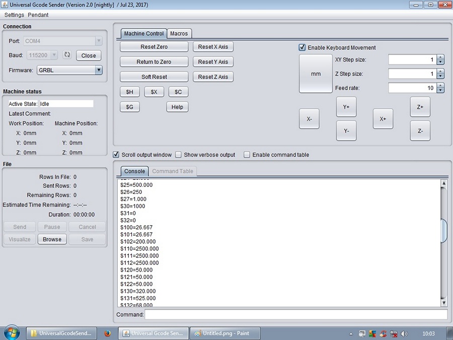
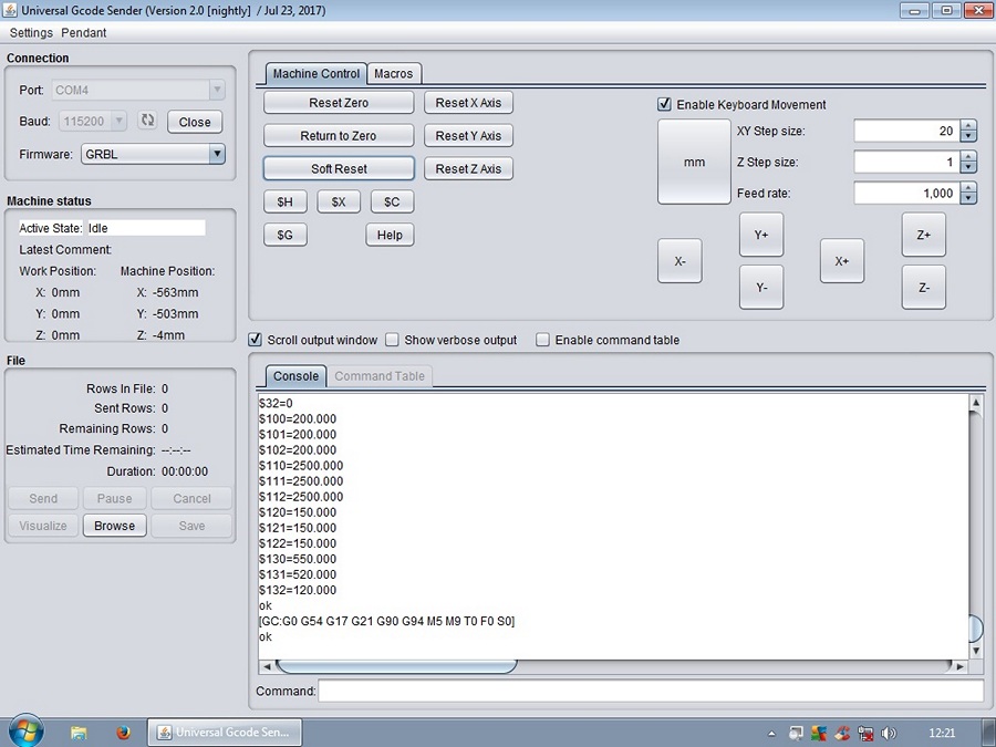
Last time I happen to mention that I would post my current UGS settings ( or GRBL firmware settings ), so here they are. They may help others to setup their 750mmx750mm correctly.
START *
$0=10 (step pulse, usec)
$1=255 (step idle delay, msec)
$2=0 (step port invert mask:00000000)
$3=6 (dir port invert mask:00000110)
$4=1 (step enable invert, bool)
$5=0 (limit pins invert, bool)
$6=0 (probe pin invert, bool)
$10=1 (status report mask:00000011)
$11=0.020 (junction deviation, mm)
$12=0.002 (arc tolerance, mm)
$13=0 (report inches, bool)
$20=1 (soft limits, bool)
$21=1 (hard limits, bool)
$22=1 (homing cycle, bool)
$23=0 (homing dir invert mask:00000001)
$24=100.000 (homing feed, mm/min)
$25=1000.000 (homing seek, mm/min)
$26=250 (homing debounce, msec)
$27=3.000 (homing pull-off, mm)
$30=1000 (Maximum spindle speed, RPM)
$31=0 (Minimum spindle speed, RPM)
$32=0 (Laser-mode enable, boolean)
$100=200.000 (x, step/mm)
$101=200.000 (y, step/mm)
$102=200.000 (z, step/mm)
$110=2500 (x max rate, mm/min)
$111=2500 (y max rate, mm/min)
$112=2500 (z max rate, mm/min)
$120=150.000 (x accel, mm/sec^2)
$121=150.000 (y accel, mm/sec^2)
$122=150.000 (z accel, mm/sec^2)
$130=550.000 (x max travel, mm)
$131=520.000 (y max travel, mm)
$132=120.000 (z max travel, mm)
* END
Before I did that though, I had to check something that had me a little confused. I've read everything I could lay my hands on and watched literally dozens of CNC builds and setups, building the cnc from a kit is the easy part, setting it up correctly had me scratching my head though, until I realised that there are two 'Homing' positions ! ............... yeah, I'm even dumber than I look !
I had to get it right in my head, so to visualise the whole concept from CAD design to CNC machining, I put together a little diagram to help others, I hope the following helps to clarify what your X,Y and Z axis' are and where they are in 3D space.
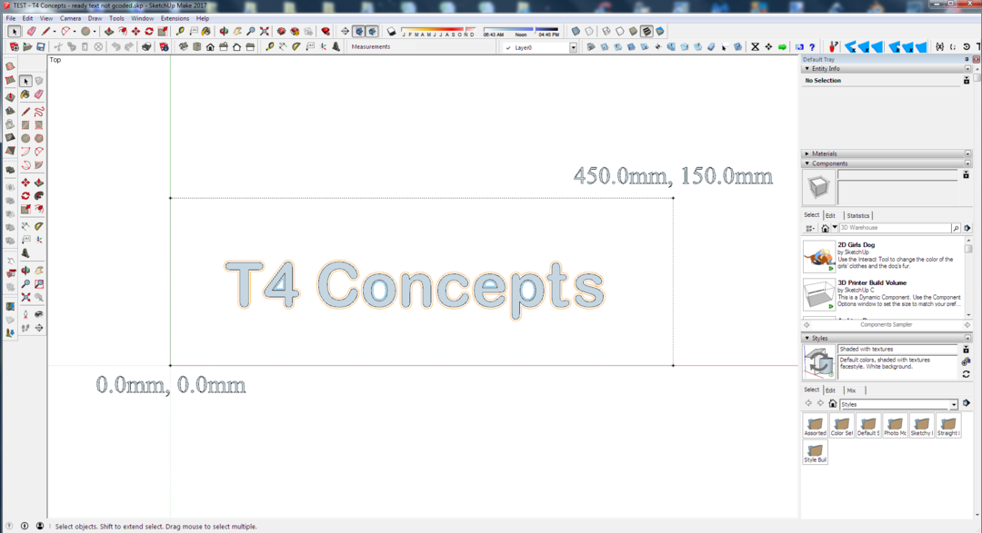
The top right hand corner ( white section ) relates to your CAD programs drawing plane, in my case 'SketchUp', only that section is used, the rest of the shaded area is never used. The yellow dot in the upper right hand corner is the 'Home' position. This is what got me confused, for a while there I thought I had setup my WorkBee incorrectly, as what I had been reading and saw in many youtube videos, their 'Home' position was front left ! Then I came across an article by David The Swarfer I think it was, where he mentions the cnc's 'homing' position and the 'work homing' position'. I've since then discovered the correct terms for these WPos & MPos. Turned out, my WorkBee cnc setup was correct. It does make great sense that your 'Machine Home' position ( MPos ) is located upper top right corner ........ that way, your tool ( spindle ) is totally out of the way so you can access your work when removing it or installing it onto the spoiler board.
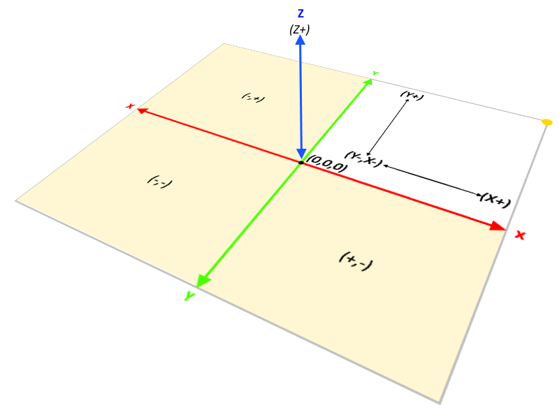
So when looking at your CAD program ( 'SketchUp Make' in my case ), you design your part within that upper left corner quadrant as in the diagram above. Here's a screenshot of how I've setup my SketchUp start file. Currently it's showing the maximum limits of my cut area of my CNC. My second 'Home' position ( WPos ) would now be set to front left corner. This now begins to make sense why you have to do it this way, because the cnc needs a reference point to start from, so everything is a negative value from the machines home position.

Having said all that, all the information is out there, just not all in one place ! Many of the directions, guides and tutorials seem to go off target very quickly when you're looking for something, things that don't really relate to what you're looking for. I'm still learning and discovering new things, if I've got any of this wrong guys please let me know in the Discussion thread, and I'll change it immediately.
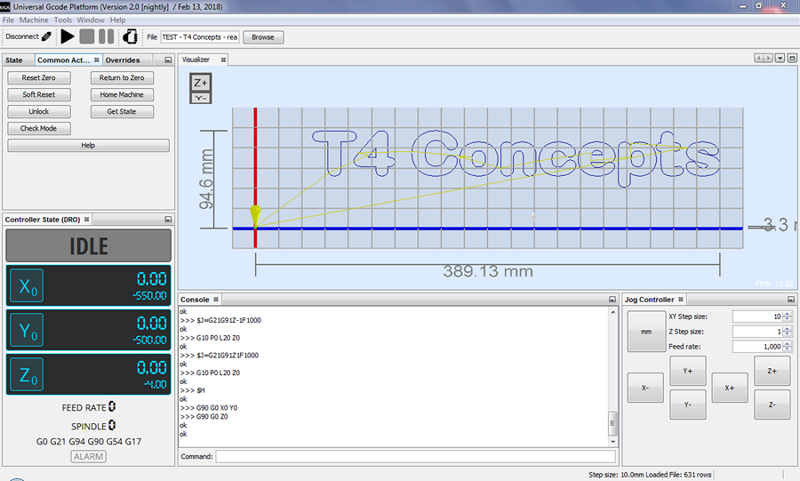
Also, another thing I just discovered ................... As I was instructed by my manual to download 'Universal Gcode Sender', you're not tied down to using the software. You can clearly see from some of the images of UGS above, that's it's rather basic to say the least. There is another version called 'UGS Platfrom', for more intuitive user interface, at this stage I don't know what advantages this gives me, but already it's looking far more professional
![Universal Gcode Platform (Version 2.0 [nightly]_900x541.png](https://openbuilds.com/attachments/universal-gcode-platform-version-2-0-nightly-_900x541-png.30352/)
Already you'll notice that the buttons indicate in words what they do, and not symbols like the previous basic version of UGS. Far more user friendly I believe. I haven't got round to making my WorkBee 'make' anything intelligent just yet, still trying to get to grips with SketchUp and having just installed the SketchUcam plugin, I've a few more things to learn yet. Once I've done that I'll cover it here also.
*******************************
Build update: 18th February 2018
Hi guys,
I thought it would be a good idea to update you all on my progress, and perhaps some newbie's may be able to glean a little information from my progress also.
The big question is, now you have your fully assembled CNC machine, you've installed the software and you've done the appropriate set up routine, and all is well ........................ now what !? What are my first steps into making my machine do something constructive or even creative ? The best piece of advise I found was, to use a pen in the tool holder and attempt to draw something, so I decided I would have a go at designing my company logo. ( I don't actually have a company to speak of really, but I do call myself 'T4 Concepts', so that's my starting point ).
As the whole point of the OpenBuilds community is OpenSource, free to use, free to share, why spend an extortionate amount of money on software that'll cost as much as your CNC did in the first place ! So, very early on I made the decision to only use free software, So my 3D design package is the very popular 'SketchUp Make 2017', my CAM software is 'SketchUcam' from PhlatBoyz, that integrates very nicely within SketchUp Make, as a fully featured CAM solution it will create the GCode required for your cnc machine. The only other piece of software that's required is a way of sending that GCode to your CNC' controller board. You could use the basic 'Universal GCode Sender' with the Classic User Interface, but there is a newer version available as mentioned above that I find much more pleasing to work with, and no doubt will be much easier to learn. So if you haven't had a look yet, you can find it here > Platform - UGS
My very first attempt at making my cnc do something creative, to draw out on a sheet of paper my logo ....... as it turned out, it was much more involved than I had originally thought. How to turn a simple text into a format that can be translated into GCode ? David The Swarfer to the rescue again ! I searched the InterWeb for what seemed hours, then I found this on YouTube 'sketchup - cutting text with sketchucam', not the best tutorial in the world

Once you're happy that your design meets your desires, it's time to generate your first GCode file
'Universal GCode Sender Platfrom' does have a GCode viewer built in, as it's always a good idea to double check your work, and that no errors have been generated by the software. Just recently I've been looking at a new type of GCode viewer called 'CAMotics', as a free piece of software I think it's fantastic so I'll continue using this for a while and see how I get on with it. You can see in the image below that the viewer ( also runs a simulation ) of the GCode tool paths, very interesting stuff indeed >>
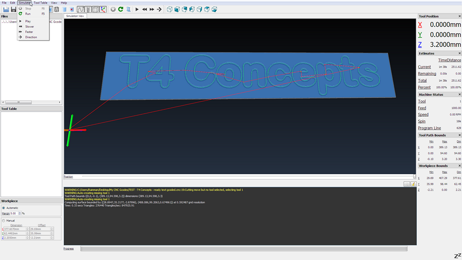
Here's a quick example of the 'CAMotics' GCode viewer and tool-path simulator >>
And here the 'UGS Platform' running ......... You may have noticed that I'm using a different laptop to run the software, so I spent a few days fixing this HP Pavilion, at least it's a Centrino Dual Core PC and not a measly Sempron ! Anyway, I have this laptop connected to my studio in another part of the house via a wireless network, so all my designs made in SketchUp are generated into GCode then I simply 'send' the file to my laptop in my workshop. I've still got my pen holder to finish so at the moment my WorkBee is just going through the motions ..................... I must say, I'm quite happy with that
Hope you all enjoyed the little update folks, and I hope that some of you may find something's helpful, maybe some of my ramblings will help to clarify uncertainties you may have. If you have any questions what so ever, or you may even be aware of something that I may of missed, join the discussion thread and we can mull it over there
Until next time.
********************************
Build Update: 20th February 2018
Hi all,
Just another quick update to my WorkBee CNC build and my first steps into learning GCode. Now that you're beginning to understand how your cnc works, and you begin to find your way around SketchUp and SketchUcam, it's now time to put some of those lessons into practice. I kept on reading and seeing in some YouTube videos, that's it's advisable to begin with a pen as a tool instead of jumping right in a breaking bit after bit, not actually knowing what you're doing. I chose to actually make a 'Pen Holder' as opposed to taping my pen to the side of my tool holder.
You may of seen in my previous update that I simply ran the Gcode as my pen holder wasn't quite ready, so the cnc just went through the motions without too much happening.
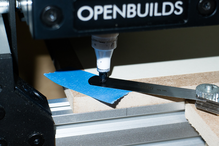
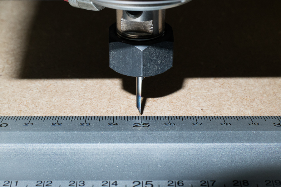
This time I was ready, all that remained to do was to 'Home' my work position ( WPos ). As my test consists of a 2D text, my company logo ........... I've seen many people 'Homing' their machines using the sheet of paper trick, that method is quite reliable as a regular 80gram sheet of printer paper is usually about 0.11mm thick. But what happens if you want to 'print' ON a sheet of paper !? I think a far better and far more accurate way of doing this is to use a metric set of feeler gauges. In the following picture I 'Zero'd' my Z axis using the 0.06mm feeler gauge ........ half the thickness of a sheet of paper basically !
Then I ran my Gcode file that I had prepared yesterday ............. and kept my fingers and toes crossed !
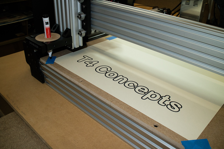
As it happens, it turned out quite well ! And it looks as though I managed to get just the right amount of pressure on the pen tip .............. more luck than anything else though I suspect ! >>
Just a couple of words on the UGS Platform - Some of you may of noticed that on the 'Controller State' window, I wasn't quite getting the entire window in, this was resulting in the Z axis figures being cut off at the bottom, I was finding this slightly frustrating. The reason for this was, my older type laptop only has a maximum screen resolution of 1280 x 800 >>
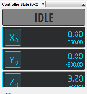
As it turns out UGS Platform is highly customisable, right down to setting up the UI as you would like it to look. So if you have a small resolution screen, I found that this set up works quite well. I just 'Docked' the JOG window over to the right, making the Console window smaller, as the lines of GCode never fills that window anyway. This leaves more room to bring the 'Controller State' window further up >>
One thing I couldn't suss out though ................... Is there a way of running a tool path previewer in the 'Visualiser' window ? as you can do with 'CAMotics ?
Well, that's it Guys and Gals, as and when I learn new tricks and tips ................. I'll be sure to pass them on
********************************
Build Update: 13th May 2018
Hi Guys,
It's been a while since my last update, I know, but I did actually mention at the beginning of my WorkBee build that I was going to 'customise' it to suite my needs. Now that I've accumulated all the parts, and built-up a small collection of end mills, I thought I would share. Maybe it'll help others to do likewise ............... the beauty of the V-Slot and C-Beam system is it's highly customisable, you can swap and change it's use at will.
We'll begin with the end mills. What bit to use and where to buy them isn't as straight forward as you will undoubtedly find out for yourselves. Reasonably good quality end mills from a respectable supplier will be the first hurdle you will encounter! as I did
Their stock seems to be of quite good quality, fast delivery ( Central France took just a couple of days ), and their prices are superb I think for what you get. Don't get me wrong, these are not high end, as I only purchased from their budget range. But they also do the 'expensive' ones. But for my tests, these will be more than adequate.
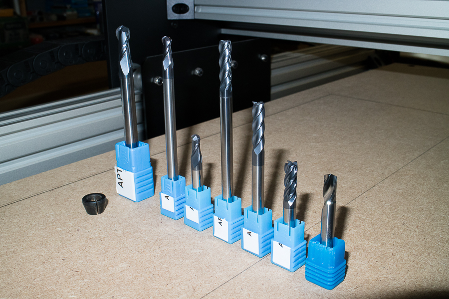
From left to right: 8mm bull nose 100mm long, 6mm bull nose 100mm long, 6mm bull nose 50mm long, 6mm end mill 4 flute 100mm long, 6mm end mill 4 flute 75mm long, 6mm end mill 4 flute 50mm long, 6mm end mill 1 flute 50mm long ( cutter ) for PVC, acrylics and non-ferrous metals. All from the 'Economy range'. So, prices ranging from £4.60 to £11.00 a piece. As far as I can tell, they're seem to be very good quality, mind you, having said that I haven't used them in anger yet! >>
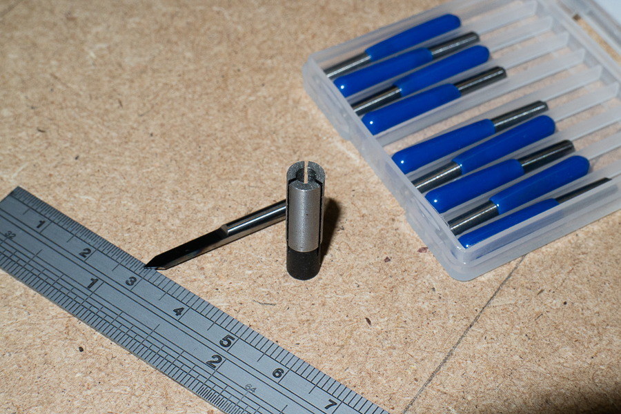
The other thing I needed, for very intricate work, and this will also come in very handy for calibrating my machine, is this tiny 'V-Carve' bit. Really designed to be used on PCB circuit boards. The thing is with these things, because they're very small ( 3.175mm ) you need a collet adaptor. So in the picture you can also see the collet adaptor that reduces the 6mm router collet down to 3.175mm >>
So, my whole collection of milling bits ................. for the time being!

And my 'PCB' bit installed into my Makita router ............... this is how I intend in calibrating my WorkBee, I don't think I'll be able to get more precise than this >>
As I'm in Europe ( France ), my Makita RT0700c was supplied with a 6mm and 8mm collets, now with my smaller adaptor, my choice of end mills has been greatly increased. Shown in the picture I have my 'monster' 8mm bull end extra long series mounted in the router. This set-up I intend in using for machining PU foams for tooling plugs >>
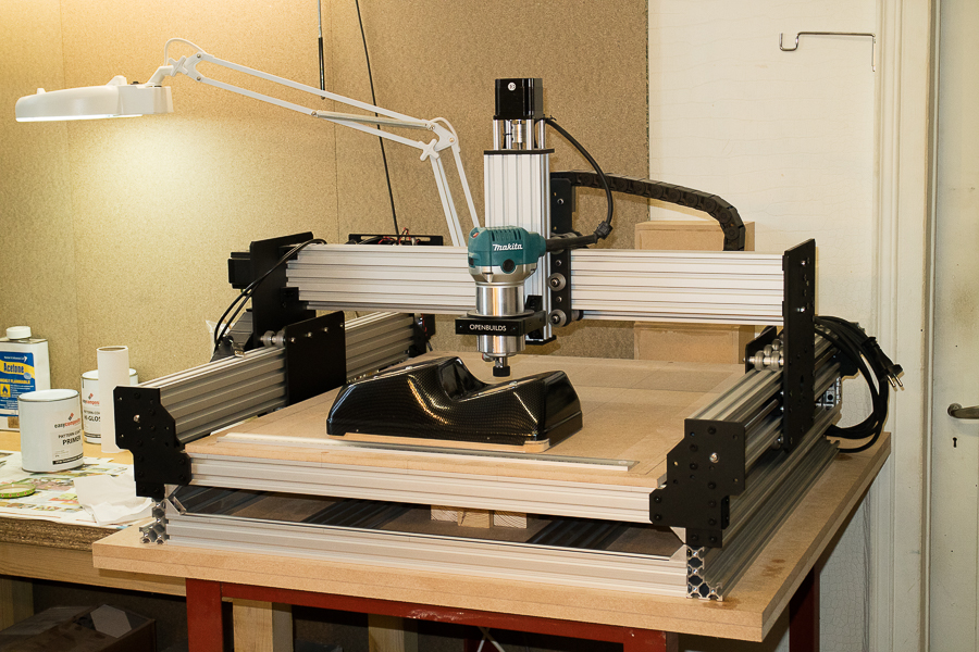
Now that I have more depth on my Z axis ( more travel ), I also need to raise my WorkBee. I could of used blocks of wood, not really my style
Some of you may be wondering why I would need to raise my cnc machine ................ and this why. Unlike most people CNC'ing I'm not machining flat pieces of wood ( or aluminium ), I'm going to try and 'Profile' ( cut holes ) in my headlight assemblies. My biggest concern right now is, will the router clear that step-down? We shall see >>
I'm already working on making a 13° wedge base to install my headlight part on, then I have to find a way on mounting that onto ( or into ) my WorkBee. That I'll cover in my next WorkBee build update.
Until then guys, cheers
TURK
********************************
Build Update: 5th August 2018
Hi Guys,
I've been contacted recently by a forum member who wanted to know how I was getting on with my WorkBee ............... I'd be lying if I said 'it does everything I want it to do'!
The truth is, I really haven't had the chance to use it in 'anger' yet!
So, I may as well take this opportunity to update my CNC build, or should I say, my WorkBee customisation. It'll also demonstrate the versatility of such a machine and the highly configurable system that is the 'Openbuilds' system.
Since I began my research in a CNC machine build, I had one goal in mind, and that was to design, machine and profile custom headlight assemblies. So I really needed something that could cope with truly 3 dimensional parts. Carving or machining flat materials to depths of mere millimetres is strictly machining in 2.5D in my mind. If however you intend on machining at greater depths, then a little ingenuity is required. So that's what I've been playing with for the last few weeks.
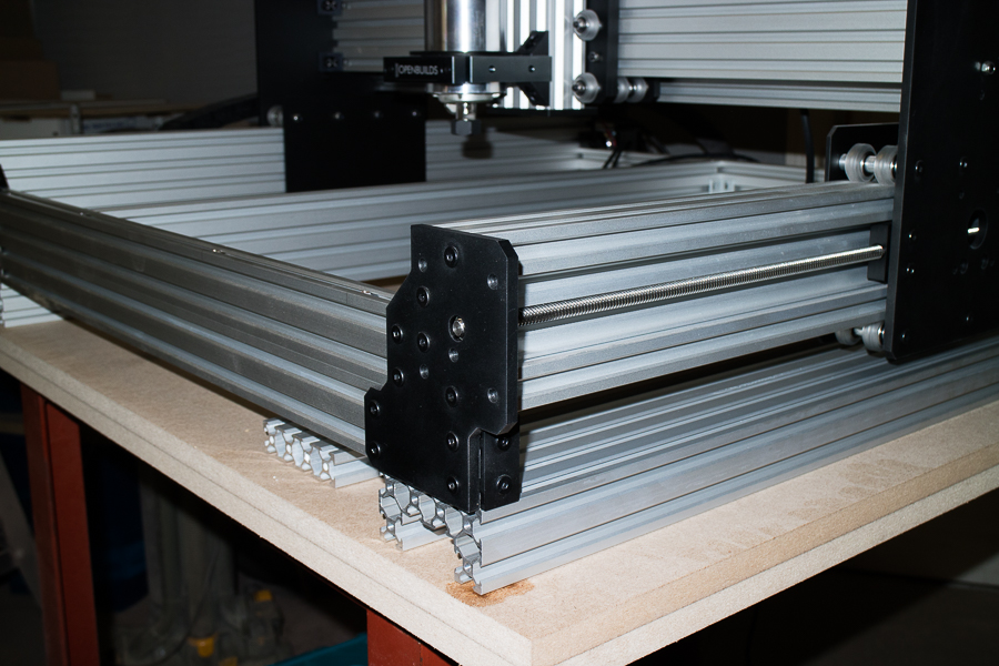
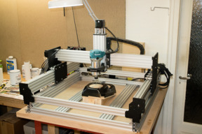
As can be seen in one of my earlier posts above, I ordered and extra two lengths of C-Beam extrusions, Tee-Nuts and dozens more 8mm screws including the corner brackets. The goal was to raise my WorkBee CNC by another 80mm so as to give me a greater cut depth without compromising the rigidity of the cnc machine. You would only need to purchase 2 extra 750mm C-Beam extrusions to do it this way, all the other extrusions are from the standard build >>
You could get the same result by building a torsion box workbench and cut a section out the middle to lower your part in, but I chose a more reliable ( I think ) alternative. You could spend days just cutting and assembling a torsion box type worktop, doing it this way I think is far easier, and far more rigid. You will also see that I now have three different cutting levels ( platforms ). In this image you can see one of my headlight parts 'inside' my cnc machine as my cutting boards have been removed >>

And in this image my cutting board installed at the 'upper level', so I can still use my cnc WorkBee for regular cnc machining. There is also a 'mid level' where I can also install the cutting boards >>
I'm now at the stage where I think my WorkBee would cope with most of my needs, I'm fine with all the hardware, but how I'm going to machine and profile these parts will come down to my ability to generate good gCode. Which will obviously mean that I need to learn how to design effective plans in CAD software.
The other thing that has me concerned are the actual bits required for cutting ABS plastics. So far I have bought a selection of milling bits, but I don't think that any would be suitable for cutting purposes as they all have flat ends on them! Could somebody recommend any cutting bits I should look at, that won't chew the plastic up please?
Would I still recommend the WorkBee for a newcomer in the CNC field .................... without a doubt!
If I would of spent all my hard earned cash on something like the popular 'Shapeoko' I doubt that I would of been able to do anything like this. The versatility of this system is the key. Money well spent!
My only regret ................. is that I didn't buy a bigger one!
TURK
T4 Concepts
********************************
Build Update: 14th September 2018
Hi Guys,
As this is an ongoing 'build', 'modification' really, I'll continue to update this thread when I complete or think of new ways of modifying my WorkBee in order to achieve certain tasks with as much accuracy as possible. Of course there are ways of doing little jobs and setting things up quickly, none of them I would consider to be effective though, I'm more of a precision man, it's the only way to get decent results. And with what I'm making, the results have to be absolutely precise!
I purchased my WorkBee CNC primarily for profiling circular holes in my headlight parts, that are mainly made of 3mm ABS plastics. At a later date I will be using it for cnc'ing headlight parts out of PU foam that I use for making moulds. So at the moment there are no intentions of driving it hard, I have no need to machine mild steel, aluminium or even hard woods. I guess I'll get to know at a later date whether my WorkBee in it's 'modified' state, is capable of machining harder materials.
Right now, this particular update is to show forum members ( or would-be WorkBee owners ) just how versatile the WorkBee kit can be. My way of setting things up may not be the usual, or even the recommended way of doing things, but they work for me
In my last update I raised my WorkBee by adding an extra two C-Beam extrusions giving me an extra 80mm on my Z axis. I then had to fabricate a jig and devise a way that I could secure the jig in place firmly. As headlight parts come in two's! I made two jigs, one for the NearSide and one for the OffSide
I didn't make a torsion-box style worktop for my machine, I found that two sheets of 16mm thick MDF was quite solid enough to take the weight, and in time I don't think the wood would warp too much, so the base is pretty solid. As I had two sheets 16mm thick, I cut a section out of the top one so I could insert my jig. The width between the two horizontal V-Extrusions is 300mm, so that's the width of my jig >>
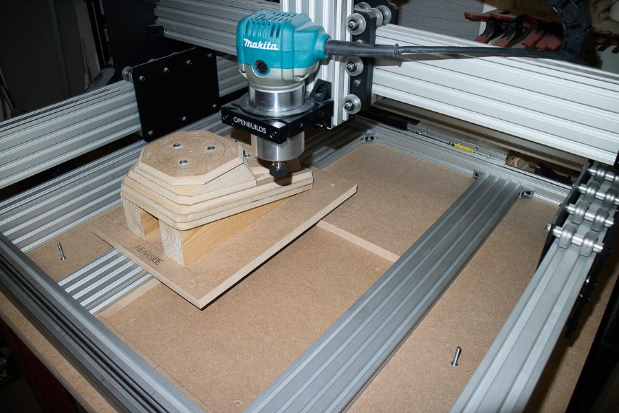
The cut-out is exactly the same size as the base of my jig, absolutely no play in it at all ....... so I have to physically push my jig into it >>
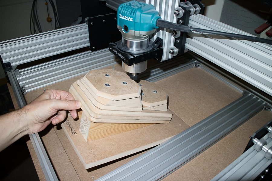
In the bottom of the two sheets of 16mm MDF I inserted four M6 'Tee-Nuts', now I can bolt my jig down securely >>
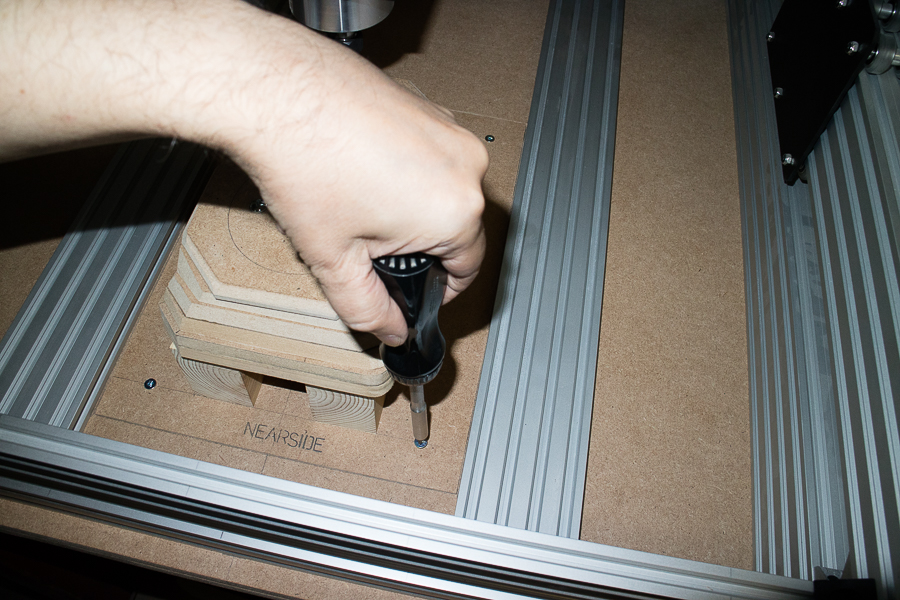
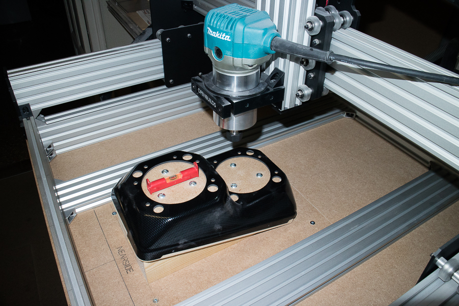
When I designed and made my wooden jig I made absolutely certain that the angle was correct, and made double sure that it would give me a level base with which to put my part on. These ABS plastic parts will be vacuum formed then installed onto these jigs for profiling, each and every hole, all 22 of them of varying diameters must be absolutely precise! Spirit level indicates that the entire setup is still dead level >>
As yet I haven't had the chance to test this setup as I'm in the process of learning a CAD program, with which I hope to transfer the design to CAM and then generate the G-Code ........................
I'll let you all know how I get on
Hope you all found this interesting, or at the very least, gave you some ideas as to how to go about your own modifications.
See you all in the next one
TURK
T4 Concepts
WorkBee CNC build - My honest opinion, tips and help
Build in 'Cartesian Style CNC' published by T4Concepts, Sep 14, 2018.
My main goal for my build is to have a machine that is capable of profiling and help me in my designs, for the manufacture of custom automotive headlights.
-
-
Build Author T4Concepts, Find all builds by T4Concepts
-
- Loading...
-
Build Details
- Build License:
-
- CC - Creative Commons Public Domain (CCO 1+)
Reason for this Build
Quad headlight project, product design