
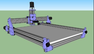
This is new territory for me, I've built a few computers but nothing like this. After scouring the Build section of the Openbuilds site, I found a likely candidate in the Halloumi CNC by Savvas. I liked the idea of lead screws verses belt drive also using temporary plates until I can mill them myself with the machine I build.
I am just getting started with it but figured if I didn't post the build as it progressed I would never get around to it, plus it's all still fresh in my mind. I don't have the entire project figured out yet but I'll weather each storm as it arises. If this build takes a year to complete it's fine with me, why rush it when you're having fun!
After making templates out of 1/4" Masonite I counter-sunk the heads of barrel bolts so they wouldn't interfere with the routing process. Later I can use the holes to bolt the plates back together for drilling holes:


The plates are made from Avonite, a solid surface material. Ready to start drilling holes:

In order to better see my marks, I covered the surface of the plate with masking tape. After carefully measuring and marking the hole centers with a extra fine mechanical pencil, I used a sharpened awl to mark the centers and followed that with a small centering bit before drilling out the final hole on the drill press:


Here is a fly by of the Vox Solid State. It's not totally finished yet, but you can get an idea of what it will look like when completed:
I needed to cut my C-beams to length and make them both exactly the same so I took a queue from DazTheGas using the router to trim them. I used a piece of 3/4" MDF and counter sunk the heads of some low profile screws so I could fasten the c-beams side by side with some t-nuts. This kept them in place when they were flipped around to trim the other ends. Once I figured out where to clamp the 90 degree fence to take off about a millimeter I added another section of c-beam so the router base would ride flat and true. I also added a couple layers of masking tape to the fence so after the initial cut I could remove the tape to just remove a wisper of a cut. They came out great, unfortunately after having some thread tapping issues I got to do it all over again, but that's a story for another day.


So like I said, I had some problems trying to cut new threads in the c-beams. I had purchased an M5 tap from Openbuilds and used it with a cordless drill to do a number of holes. When I tried running a bolt in I noticed some of the holes where kind of sloppy and a few were stripped about halfway in. Even though I backed out the tap as I was cutting the threads, the chips just didn't clear very well and the job suffered, (I should have used some type of cutting fluid.)That is why I had to shorten up the rails enough to get rid of the damaged threads. I found a metric M5 tap locally and with a spritz of WD-40 cut the new threads by hand, turning it in about a half turn and then backing off a bit to clear out the chips of aluminum, rinse and repeat and repeat etc.... After about an hour I had finished and the threads looked wonderful! It's so much easier to feel how the tap is cutting when doing it by hand verses using a power drill, lesson learned!


Moving on, I am using double wheels on the x-axis plates and I knew there would be a problem getting both wheels sitting down perfectly in the v-slot. From everything I've seen so far it goes like this: spacer (or eccentric), precision shim, wheel, precision shim, spacer, 2 precision shims, wheel and nylon locknut. This will get you close, but not right on, so I decided to make my own custom spacer to fit between the wheels by itself without any precision shims. I made a jig finding just the right size bit to drill a hole for the aluminum spacer, then I cut them a little over size on the table saw, (not for the faint of heart because they like to spin and come out of the hole). Using a 90 degree fence on my edge sander I gently took off a little bit at a time until I got the length I needed.
I updated my "spacer jig" with a hold-down bolt so the spacers now stay firmly seated while cutting and sanding! I don't recall exactly what length I finally found to work but when I take the assembly apart again I will measure and post it.


Spacer jig update: After numerous attempts at making the aluminum spacers I gave up on the jig with the hole drilled in the side because it was impossible to hold such a short piece square and I always ended up with one side a few thousands off. I still use this jig to cut the spacers to length on the table saw.
Spacer jig v.2! After pondering my dilemma for a few days I came up with an easy solution. I chucked a 13/64 bit in the drill press and drilled out the center of a 45mm spacer, removing just a whisker. Now I could slip the spacers on the 13/64 drill bit and slide it against the fence while sanding off the final few thousandth's. It's working great and even a short spacer comes out quite square, it's amazing how fast aluminum heats up, you may need to wear gloves. D'oh


As long as we're talkin spacers: Can anyone tell me why the Openbuilds anti-backlash blocks have a hole countersunk on the front side that is 9mm in diameter? It would've been sweet if it were 10mm, then an aluminum spacer would slip right in. I needed to keep the nut block 4.some millimeters away from my Y-plate so instead of stacking up a bunch of washers I thought the spacers would look pretty and actually help hold it in place. I am not a machinist nor do I have the right tools to do this so I had to get a bit creative. At first I tried to sand/file down an aluminum spacer on my drill press to a diameter of 9mm, but that was very time consuming and not very accurate. Then I thought why not just reduce the diameter of the end that fits in the anti-backlash block, so I drilled a 1/2" hole for a carbide router bit and made a poor man's lathe (see the video). It worked surprisingly well!


So I finished drilling the y-axis plates, I did make a test plate out of 1/2" plywood just to make sure the holes for the eccentric spacers were the right distance apart. Everything seems to work ok, although I might move the eccentric holes on the final plate just a tad closer to the fixed wheels as I was close to running out of adjustment. I also found that the access hole for the anti-backlash block was 10mm too high on the left side plate, plus I think if they were square instead of a triangle it may be easier to adjust the block later on.
When I checked the plates for square they were leaning out just a bit at the top so I checked the end plates and after a little adjustment everything squared up nicely, plus I think it helped leveling the frame.
The closest bit I had for drilling the bearing holes is a 5/8" forsner bit, and it was a shade too small for the lead screw bearing to fit. I chucked a 5/8" bolt in the drill press and used a metal file to reduce the diameter then used some spray adhesive to attach some 320 grit paper. With light pressure I was able to enlarge the hole enough for the bearing to snap in. (see video)
With both y-plates rolling smoothly I cut the c-beam and the 20x40 v-slot extrusion that mounts underneath the bed and screwed it in place. It's nice to be able to actually see some parts moving.


Today I worked on the zed-plate, as they say across the pond.I already had a Bosch Colt router in my wood shop and since Openbuilds offers a spindle mount that's the correct size for it I figured, why not! The plate design comes from Savvas and in his build he used an upper and lower mount to secure the spindle. With the Bosch there's a limited area to fasten a mount so it needs to be very rigid.
The design I came up with uses two outer supports, kind of like arms on a chair, with a dado to accept the spindle mount. I had planned to permanently attach these arms to the plate with solid surface adhesive but after I drilled and tapped holes for 4 m5 bolts I realized it was rock solid. The spindle mount can slide in and then be bolted from the sides and back.


Hey, I'm back. Had a new knee put in and I'm on the mend. I finally got around to wiring up the Arduino Uno with the drivers and steppers to make sure it all worked before I find a suitable case for all the components. My main concern was if the Uno would work with 2 Y-axis steppers, they did just fine. I think my Granddaughters will enjoy seeing themselves twirling wildly!


I started work on a spoil board and I knew I wanted to counter sink the m5 bolt heads so I didn't crash into them while running an operation. The perimeter holes were not a problem, I could reach them with a drill press, but the interior holes caused me to scratch my head, so I came up with this jig. I pressed a drill bit guide into a scrap 1x4, then used a brad point bit a little larger than the head of the m5 to make the counter bore. I found a piece of tubing that fit over the bit to make a depth stop that kept all the holes the same. The center locator is just a drill bit with a bushing taped on so I could keep the counter bores centered over the already drilled bolt holes. 2 c-clamps held the jig firmly in place while I made the bore holes.
After some trial and error I have everything up and running including the proximity sensors and the opto-coupler. I was a little concerned that while working on the homing cycle I would crash into the end stops so I installed some springs on the sensors to give me enough time to lunge for the power switch if needed. (see video)
Power to the opto-coupler's high side is provided by the 24 volt power supply and the low side receives 9 volts from a power converter. I originally tried using a 5 volt supply but the signal to the Arduino Uno was only 3 volts, with the 9 volt supply it's in the neighborhood of 5 volts.
I thought it might be useful to someone out there struggling with sensors or opto-couplers to have a schematic of the wiring that worked for me. I used Sketchup to draw it so I'll include the skp. file plus a pdf of it. (It may be difficult to make out all the wiring on the pdf so the best bet would be to view it using Sketchup.
These are the components I used in my build:


Ha, where does the time go? It's been over a year since I last posted anything, my cnc is up and running great so I thought I'd better at least upload some photos of the completed project.
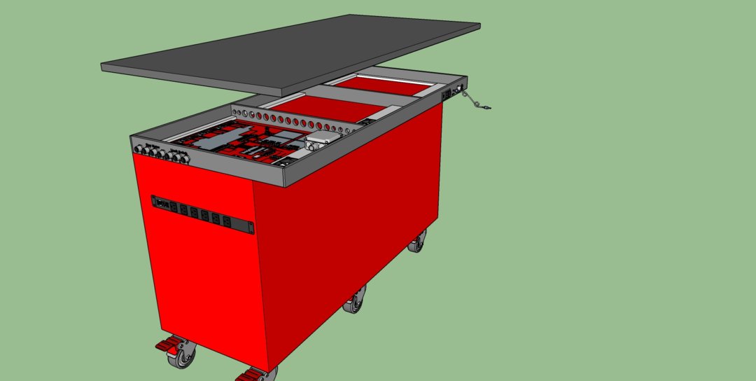
Side note: I finally purchased a dedicated cnc cart so I no longer have to move it to my shop table every time I want to use it. I found this sweet Milwaukee 61 inch mobile work bench at Home Depot, it's not quite wide enough for this cnc so I will be replacing the wooden top with a 30 inch wide Corian counter top. I plan on raising the top 3 inches to give me space for all the controller electronic. The projects never end!


So I got a start on the mobile cnc cart, a few pieces are machined, now I'm just waiting for a couple parts. I drew it up in Sketchup and will post the file plus an image here.
Vox Solid State
Build in 'Cartesian Style CNC' published by CharlieShimota, Mar 15, 2019.
I never thought owning a CNC machine was possible until I stumbled upon the Openbuilds site. After viewing numerous builds I was drawn to the Ox by Mark Carew but ultimately decided on a build of similar design, Halloumi by Savvas. It's a C-beam design driven by Nema 23 steppers with Acme lead screws. Like Savvas I will be fabricating temporary plates to get up and running then use the machine to mill the final plates. The material I'm using for the temp plates is solid surface (Avonite).
-
-
Build Author CharlieShimota, Find all builds by CharlieShimota
-
- Loading...
-
Build Details
- Build License:
-
- CC - Attribution - CC BY
Reason for this Build
I love building things, from homes to computers. This will be a fun challenge because of the small scale.Inspired by
The Ox - Mark Carew and Halloumi - Savvas -
Attached Files:


