I recently sold my custom delta build so I decided to start a new build. I needed something that was a bit more robust to meet my use case. This is the result.
Design Considerations
Features:
- Mid-range build cost ($700-$1000)
- Reasonable print area (200x200x380), Can grow to 200x300x380
- Capacity for change/growth, extra space in the frame
- Fully enclosed - nothing hanging out on top of the machine (filament, electronics, belts, etc)
- Controlled airflow
- Multi-material Capable
- Movable with minimal re-calibration (just throw it in the back seat of your car, it will print the same when you get to your destination)
- Capable of long term prints
- Easy local and remote monitoring (use OctoPrint from your tablet or phone to view progress)
- Laser cut shell and "plates"
- Bright! 5m of multi-colored LED inside the t-slot and v-slot.
Status Update 1: April 4, 2015 (Version 1.1)
- All axial movement using Belt and Pinion (with mini-wheels)
- MK3 Heated Bed
- RAMBO 1.2d Board
- Integrated RaspberryPi with PiCam and Octo-Print for remote monitoring
- Multicolour remote controlled LED
Status Update 2: April 13, 2015 (Version 1.2)
- all of the parts ordered, from various suppliers (Canada, US, China)
- acrylic purchased locally, needed 14 - 1' x 2' (3/16" thick) sheets @ $10 per sheet = $168 CDN (taxes)
- a note on the acrylic... I went with 3/16" because I wanted something really rigid (no bowing or flexing) to assist with the structure of the frame, guess what? 14 pieces of 2'x1'x3/16" acrylic weighs about 30 lbs. Good thing light weight wasn't one of my design goals.
- used a laser cutter I have access to, to start cutting cardboard sections to "visualize" the design of the shell, proceeded to break laser cutter, waiting for it to be fixed before cutting more shell elements from cardboard (if they allow me to use it again).
- decided on 2020 t-slot for the basic frame instead of v-slot, used t-slot because it is a bit cheaper for non-movement elements and I can source it closer to home (read: reduced shipping), needed 8m in total, was able to get it for a killer price.
- identified a slight design defect in the x-axis v-slot length, I originally thought I needed to shorten the length of the x-axis v-slot because I wanted to use 2, 1500 mm lengths to do all the axial movement with no left over pieces, there are two 150 mm pieces that connect the y-axis to the t-slot, if I made these slightly shorter I would be able to use the extra length to extend the x-axis, Doh!
- I have updated the design reference to fix the problem above but now the pieces I have on hand to actually do the build are different than the design. Learning is fun.
- made the mistake of purchasing the mini-V wheels through a supplier in BC (ProtoDrake), 3 weeks out from the order and they haven't changed the status of my order from 'Awaiting Pickup', I paid for shipping, tried to contact them multiple time for an update, no response, cancelled order and repurchased items through OpenBuilds.
- updated the build plate, the corner holes to mount the build surface were too close to the edge of the build plate which would have lead to cut errors.
Status Update 3: April 19th, 2015 (Version 1.3)
- updated the major version number from 3 to 1 (there are not 2 other production versions)
- updated the design to use the cast aluminum 20x28x28mm 90 degree angle connectors
- added the 40mm low profile fans
- decreased the size of the top fan vents to use less material
- built the "feet" on the printer using the corner joins
- demo of belt and pinion design using the laser cut acrylic plate (4.3mm)
*Build Pics *
Y-Axis
z-axis plate with motor
Status Update 4: April 25th, 2015 (Version 1.4)
Status Update 5: May 3rd, 2015 (Version 1.4)
- updated the shell to account for the "channel alignment tabs" on the 20x28x28mm 90 degree angle connectors
- fixed the x, y, and z axis plates to correct for the actual dimension of the corner joints
- re-positioned the stepper motor on the y-axis build plate, it was a bit too far from the v-slot, further than the other plates
- changed out the reference motors for the stepper motors that match the dimension of the purchased motors (actual motors were a few mm shorter than the OpenBuilds stepper motors used in the reference design).
- updated the shell on the production build to match the actual thickness ~4.3mm (it is currently at 4.7625mm or 3/16")
Status Update 6: May 24rd, 2015 (Version 1.4)
- Starting on build of the X/Z and Y axis.
- Movement test video will be uploaded soon.
- Frame mostly complete.
- y-axis attached.
- need to make change to the x-axis, some dis-assembly required. (ARG!!)
- using jam nuts was a pain in the but
Status Update 6: May 31st, 2015 (Version 1.4)
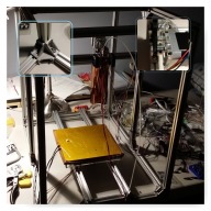
- Build substantially complete, still working on shell
- Print head attached to the x-axis using magnets with 10lbs force.
- Next step to confirm movement.
Status Update 7: June 14th, 2015 (Version 1.4)
Still To Do for Next Iteration
- movement tests (will post video soon)
- wire routing
Still to Do After this Design is Complete
- build a vibration protection "plate" on the feet.
- fix the darn screws, you know, the darn screws, fix them
- and put some proper nuts on them, seriously...
- rebuild using parts from the Open Builds store and publish a parts list should anyone decide to build.
V 1.4 - Bright Box Cartesian Printer - *BUILD PROGRESS PICTURES
Build in 'Cartesian Style Bots' published by Darren Ditto, Jun 14, 2015.
Cartesian Printer, 200mm x 200mm x 380mm build area, enclosed, belt and pinion movement, heated bed, Raspberry Pi, Pi Cam, OctoPrint
-
-
Build Author Darren Ditto, Find all builds by Darren Ditto
-
- Loading...
-
Build Details
- Build License:
-
- CC - Attribution NonCommercial - Share Alike - CC BY NC SA
Reason for this Build
I needed a build that I could move between home and the MakerLab on a regular basis without significant re-calibration. I used to have a large delta that was too tall to stand-up in my car or truck so I had to lay it on its side for every movement, get it to the destination, then spend 20 minutes getting it printing just right. With this design I have something that is significantly more robust, will fit in both my vehicles, and will not need tinkering at the destination. Oh, and I can use it for a coffee table. -
Attached Files:
-
![[IMG]](proxy.php?image=http%3A%2F%2Fi.imgur.com%2FCmWkuqrl.jpg&hash=a42cf5cb5b30b779115a93ef19532634)
![[IMG]](proxy.php?image=http%3A%2F%2Fi.imgur.com%2Fc6oeoiEl.jpg&hash=5800cc95bb421256b9fb87222d31a5b8)
![[IMG]](proxy.php?image=http%3A%2F%2Fi.imgur.com%2Fu7uxBlMl.jpg&hash=a556dd1787b8a8e8166975178b69dc5d)
![[IMG]](proxy.php?image=http%3A%2F%2Fi.imgur.com%2Fbb37usNl.jpg&hash=1e3245c267eb5c06bd4b13609c5d5d25)
![[IMG]](proxy.php?image=http%3A%2F%2Fi.imgur.com%2FRI8JCwKl.jpg&hash=99be03ba42b58a59fb4351a3111a6745)
![[IMG]](proxy.php?image=http%3A%2F%2Fi.imgur.com%2F8aEZtqFl.jpg&hash=83ceccacd15a40de431ea6da5a53d8a8)
![[IMG]](proxy.php?image=http%3A%2F%2Fi.imgur.com%2F1b6sbWBl.jpg&hash=d2ee8c48ccfea2466c2a3d613e1bfc30)
![[IMG]](proxy.php?image=http%3A%2F%2Fi.imgur.com%2FvaKkOm0l.jpg&hash=843a24ee60dddf0a1b17786c076d54ff)
![[IMG]](proxy.php?image=http%3A%2F%2Fi.imgur.com%2Ft8VXf6ll.jpg&hash=bac3bb3d6719d7c538a831e156f17921)
![[IMG]](proxy.php?image=http%3A%2F%2Fi.imgur.com%2FghgS2Yxl.jpg&hash=5eb57394a8ad1f368a3faa3f6ee80973)
![[IMG]](proxy.php?image=http%3A%2F%2Fi.imgur.com%2FGomcQOYl.jpg&hash=8467e54566109c5a0ba869fc1e33a258)
![[IMG]](proxy.php?image=http%3A%2F%2Fi.imgur.com%2FDLdpsBdl.jpg&hash=115c33fd0e5e7d2a3567015c941ff174)
![[IMG]](proxy.php?image=http%3A%2F%2Fi.imgur.com%2FZ0K2WSGl.jpg&hash=48f4fd29bf516b49df82d4fb92685e15)
![[IMG]](proxy.php?image=http%3A%2F%2Fi.imgur.com%2F434yhool.jpg&hash=477559cc22c42f2af22efe9e597b9b6b)
![[IMG]](proxy.php?image=http%3A%2F%2Fi.imgur.com%2F6ZBMFRll.jpg&hash=783e6c257d7ecceebf209a616d1ea6f8)
![[IMG]](proxy.php?image=http%3A%2F%2Fi.imgur.com%2FOCxyFhPl.jpg&hash=3378e534dd936161864b219603d3bda6)
![[IMG]](proxy.php?image=http%3A%2F%2Fi.imgur.com%2FLLQNh9ul.jpg&hash=76d5fa0397855083e4be54aae68bacc8)
![[IMG]](proxy.php?image=http%3A%2F%2Fi.imgur.com%2Ff8nDBRJl.jpg&hash=efc82f4d4d1bcc44892907d1821afbf6)
![[IMG]](proxy.php?image=http%3A%2F%2Fi.imgur.com%2Fc5mmHmbl.jpg&hash=ec824c3e51dd55f2ad8db6edcaa92584)
![[IMG]](proxy.php?image=http%3A%2F%2Fi.imgur.com%2FPHFFHiDl.jpg&hash=ae4cbd6fec4ff5de749412618ceba316)
![[IMG]](proxy.php?image=http%3A%2F%2Fi.imgur.com%2FCt4K8Zal.jpg&hash=a5c23a3d225cdf7e0a701cc30324351c)
![[IMG]](proxy.php?image=http%3A%2F%2Fi.imgur.com%2FmfAaPBOl.jpg&hash=d1b13b94ed4ddaa4132cd66a6e3525d7)
![[IMG]](proxy.php?image=http%3A%2F%2Fi.imgur.com%2FUhPcKhQl.jpg&hash=ab80a595bd34f8d29952af07c4e3dd33)
![[IMG]](proxy.php?image=http%3A%2F%2Fi.imgur.com%2FXHzaj0ml.jpg&hash=1f2745eae81dbb43f2883b918acc8d1d)
![[IMG]](proxy.php?image=http%3A%2F%2Fi.imgur.com%2FbRZfRQ0l.jpg&hash=a6b35e2c4b91485ac4eed5ca7873be70)
![[IMG]](proxy.php?image=http%3A%2F%2Fi.imgur.com%2FvoPminxl.jpg&hash=b86af0595546c3a312adf18491b20996)
![[IMG]](proxy.php?image=http%3A%2F%2Fi.imgur.com%2Fpe3XMQdl.jpg&hash=93b2f134363dfffe058da8b84c068eba)


