Tool Position Setting Part 1.
X – Y positioning.
I do quite a lot of label and instrument panel engraving using ‘Traffolite’ (a multi-layered phenolic plastic) and in most instances the work is cut to size first and the engraving layout is then centered on the blank. Centre finding of the work is just a matter of drawing two diagonal lines, corner to corner and where they cross is the centre. To zero the machine to this centre position is relatively easy if the tool is an engraving point but becomes much more difficult when using a ‘slot drill’ or ‘ball nose’ tool. Please note that the following is Mach3 related and all dimensions are in millimeters.
One solution to this problem is to use a cheap and readily available laser ‘cross hair’ pointer and the following describes how I have implemented this with my Mach3 setup. Obviously, there is always more than one way to do everything so please feel free to make changes and / or improvements to this implementation as you see necessary.
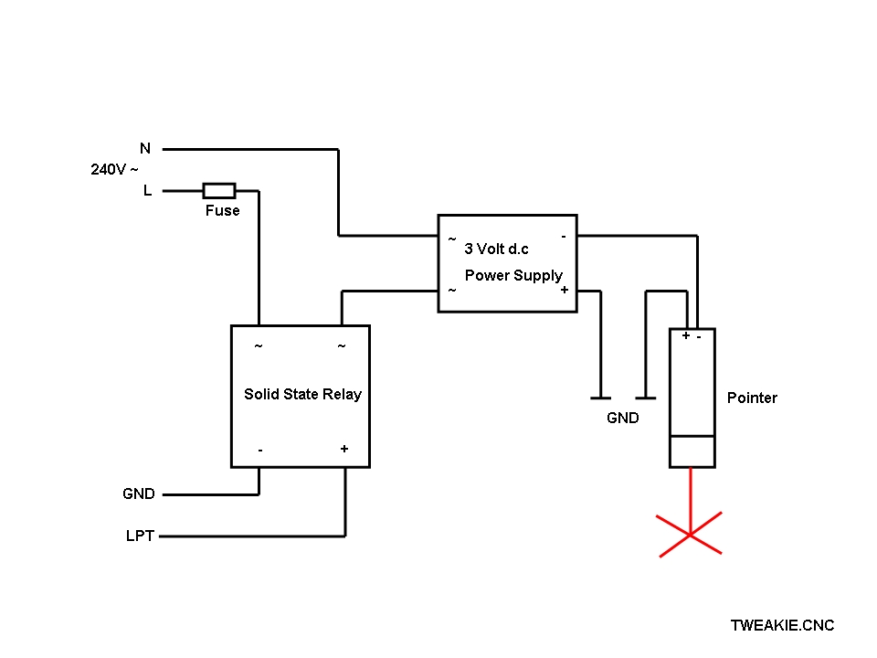
The cross hair pointer is fixed to the Z axis (as close to the spindle centre as is reasonably practical) then the offset (between the pointer position and the tool position) is measured using the X and Y axis DRO’s. I have used one of the screen designers to add two new buttons to the Mach screen – one for turning the pointer on / off and the second to home the spindle (tool) to the current pointer position on the surface of the work.
To use, I mark the surface of the work with the datum point (usually the centre), turn on the pointer and jog the X and Y axis until the cross hairs align with this datum mark then click the ‘Home to Sight’ button – the X and Y axis then move so the spindle is now aligned with the datum.
This method of positioning is extremely quick and easy to use and it has now become a tool which I would not be without.
It should be noted that the accuracy I am able to achieve with this device is better than 0.5 mm and whilst this is just fine for a router (where alignment is often to a pencil line on the surface of the work or the edge of an engraving blank) it would not really be a suitable addition for a mill which may require precise alignment to an edge where the conventional edge finders can achieve a much greater degree of accuracy.
There a number of problems with laser cross hair pointers which have to be overcome.
(1)I found, with my version, that the metal casing of the pointer is electrically connected to it’s positive (+) supply and as my machine is of all metal construction (with the frame electrically connected to GND) and with the pointer mechanically and electrically connected to the frame it needs a negative (-) supply.
There are a number of different ways to resolve this issue but I chose to use a small, isolated, dc power source (ex-mobile phone charger) which has it’s positive (+) output connected to GND (machine frame) and it’s negative (-) output connected to the pointer with the on / off switching accomplished with a solid state relay.
(2)The optical output from the cross hair pointer is extremely bright andbecause the reflectivity of various materials and their surface textures vary it is desirable to be able to adjust the apparent brightness of the cross pattern. In addition, it is a factor of our eyesight that makes coherent laser light appear to ‘sparkle’ therefore the narrower the perceived beam width the better it is to view.
As the photon beam from diode lasers is plane polarized I have fitted a rotatable disc incorporating a piece of polarizing film and when this disc is rotated between 0 degrees and 90 degrees the apparent brightness varies from full on to completely off thus enabling an optimum brightness to be selected.
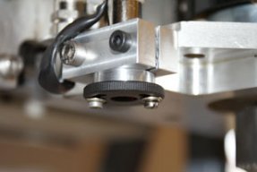
(3)The Chinese seem to be the masters of the ‘sloppy fit thread’ and the focus ring (incorporating the cross pattern) will move during use unless it is suitably locked in position.
When clamping the pointer to the machine frame I have also clamped the focus ring. It is a bit tricky to initially get it set correctly, when done this way, but it only has to be done once and it is worth taking the time to get it right. The focal distance has to be set to an optimum for the travel of the Z axis and the pointer has to be mounted perpendicular in both planes so that the position of the cross pattern does not move (on the surface of the work) when the Z axis is raised and lowered. The orientation of the cross pattern is not that critical as it is only the crossing point that is used but I have aligned mine with the X and Y axis (at least, as near as I can).
To operate the cross hair pointer, as mentioned earlier, I have added two new buttons to the Mach3 screen. These are VB buttons and can be easily added using one of the free screen designer programs available from the Artsoft website.
The ‘SIGHT ON/OFF’ button will toggle the pointer on/off (turn it on if it is off and turn it off if it is on) and within Mach contains the following script ;
If IsOutputActive(OUTPUT5) Then
DeActivateSignal(OUTPUT5) 'turn off pointer
Else
ActivateSignal(OUTPUT5) 'turn on pointer
End If
Here I am using Output #5 which is mapped, within the Mach3 setup, to the LPT output pin connected to the solid state relay shown in the previous schematic.
The ‘HOME TO SIGHT’ button will move the X and Y axis to the position of the cross hair, reset the X and Y axis DRO’s to zero and turn the pointer off.
This VB button contains the following script ;
Xs=GetOemDRO(59) 'Xscale DRO
Ys=GetOemDRO(60) 'Yscale DRO
Xmove = -73.8344 * 1/Xs 'move distance adjusted for Xscale factor
Ymove = 10.5625 * 1/Ys 'move distance adjusted for Yscale factor
DeActivateSignal(OUTPUT5) 'turn off pointer
Code "G91 G0 X" &Xmove & "Y" &Ymove ' makes an incremental move
While IsMoving () ' waits while that happens
Wend
Code "G90" 'goes back to absolute moves
DoOEMButton (1008) 'zero X DRO
DoOEMButton (1009) 'zero Y DRO
The ‘Xmove’ and ‘Ymove’ values, in the above script, will need to be changed to suit the positioning of the pointer on your own machine but they can be easily measured by fixing a piece of scrap to the work table and then by using an engraving point in the spindle making an indentation into the scrap. The X and Y axis DRO’s are then zeroed, the pointer turned on and the X and Y axis jogged until the cross pattern is exactly centered on the previously made indentation. The X and Y axis DRO’s will now read the correct values to be entered into the script, changing the sign (+ or -) as necessary (In my case, the spindle is offset from the pointer in the –X and +Y directions so the sign of the values in my script reflect this offset).
I think I have covered everything here but if I have missed anything or failed to explain anything clearly please ask.
In Part 2. I will describe my implementation of ‘Auto Tool Zero’ or tool height setting relating to the surface of the work.
Tweakie.
Tool position setting Part I
Build in 'CNC ROUTER BUILDS' published by Tweakie, Apr 27, 2014.
The method used for tool position setting is a matter of personal choice but this is what I do.
-
-
Build Author Tweakie, Find all builds by Tweakie
-
- Loading...
-
Build Details
- Build License:
-
- CC - Attribution Share Alike - CC BY SA