
I am currently studying a Bachelor of Engineering Technology (Mechanical) at AUT in Auckland, New Zealand.
I started this build in my holidays a few months ago and have been working on it in my spare time since then, it features an E3D hotend in a bowden configuration with a dodgy chinese aluminium extruder I bought on aliexpress. The total cost of the first version was around $1000 NZD (about $670 USD) but would cost a fair bit less if I didnt have to pay to get parts shipped halfway across the planet.
I had been wanting to build a 3D printer for a while but not having a 3D printer to make the parts for one with, and not knowing anybody with one, I decided to design one using off the shelf non-printed parts.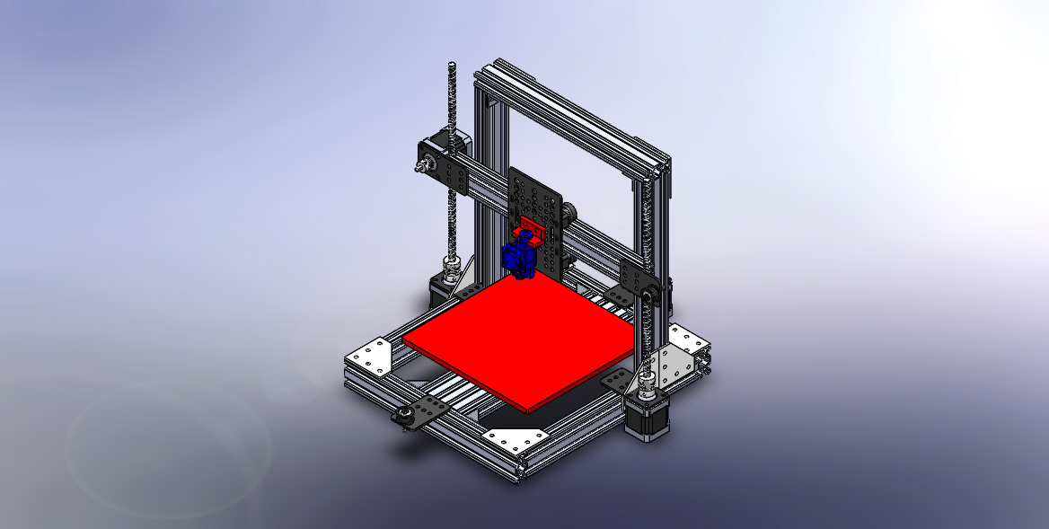
I made an assembly on solidworks using parts from the openbuilds part store, ordered them and some others from aliexpress and built the first model.
The initial test prints I did were average at best, but I think I have worked out the biggest problems and am in the process of upgrading my printer in the hope of higher quality prints.
The BOM I uploaded is what I would buy if I was going to make another printer from scratch, using just the openbuilds part store and differs from my printer in some aspects.
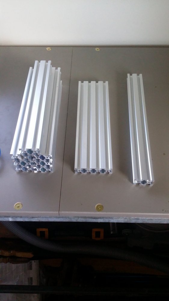
The lengths of the v-slot that I would recommend using would be 350mm for all pieces except the x-axis which must be longer, this should allow a 200*200*200+ build volume.
Mine uses 290mm lengths and its slightly too small but still allows a 170*180*155 build volume.
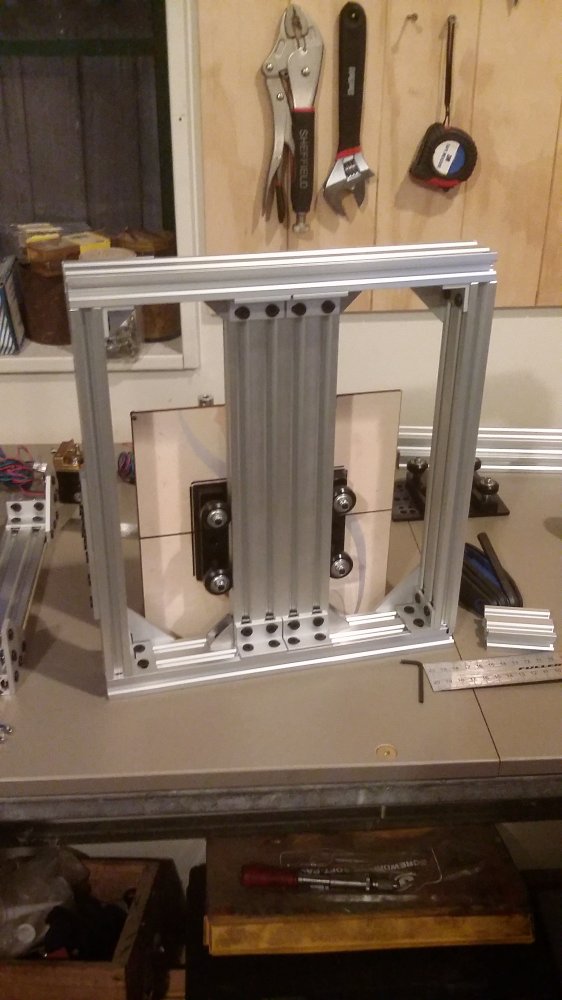
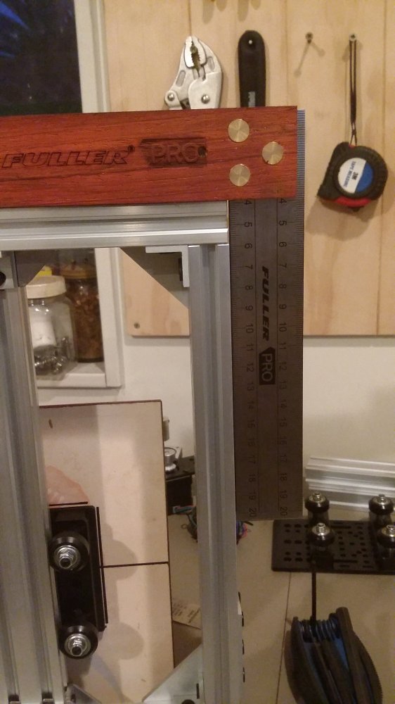
With accurate cutting and filing (or milling if possible) it is possible to get a very square and rigid frame, this can be quite fiddly to get right but its worth putting in the time to get it right.
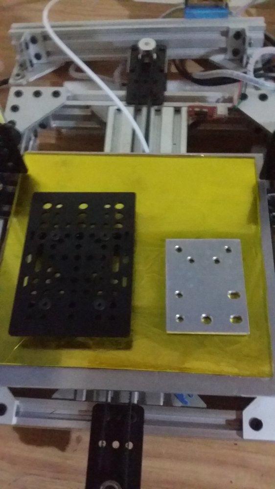
The x-axis is mounted to the 20mm universal plates as shown below, I used 2 washers to support the middle and help stop the v-slot getting warped by the pressure of the screws.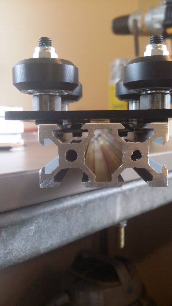
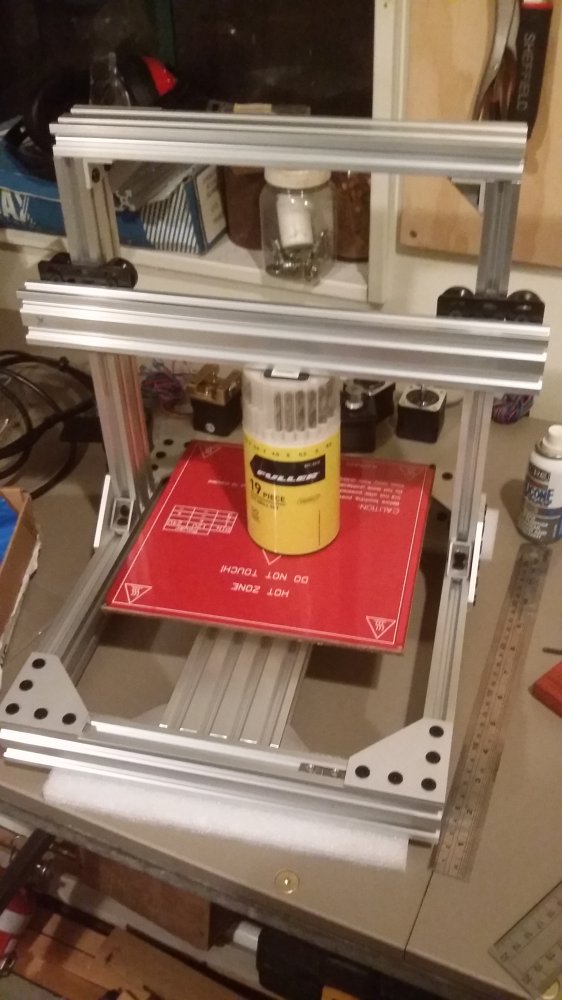
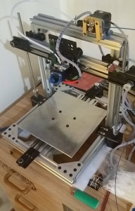
This is the only picture I can find of the printer while it was (almost) together, ill upload some better ones once I have it all back together and upload an updated solidworks assembly.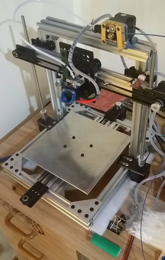
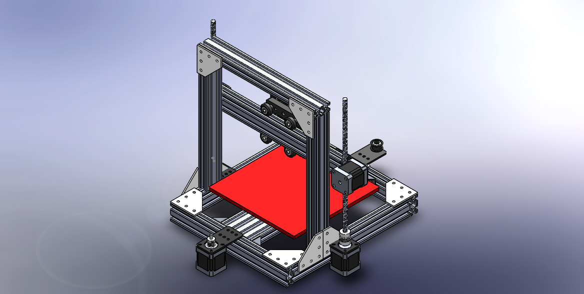
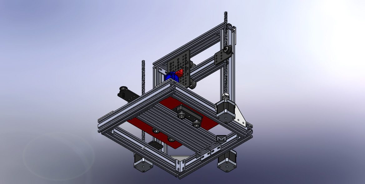
Since beginning the project I invested in a small milling machine and have made a much smaller x-axis plate, and made the following changes to the design.
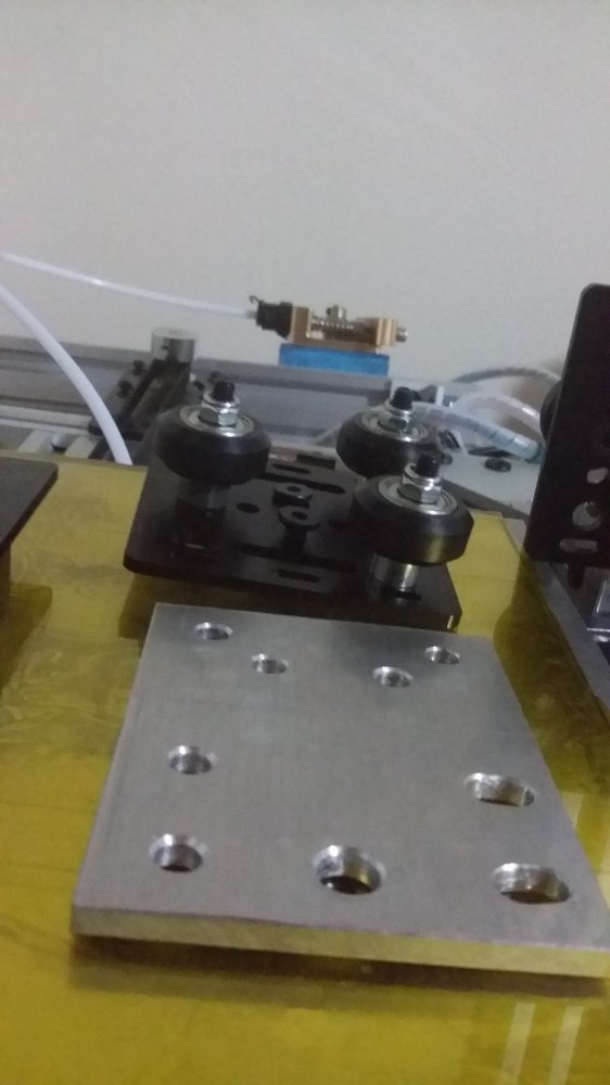
- changed to 3 wheels instead of 4 on the z and x axis plates as it is much easier to get even pressure on the wheels
- swapped out the 4 start, 8mm lead z-axis leadscrews for single start, 2mm lead ones as the load on them was causing them to overdrive, I suspect this was the cause of the uneven layer heights that were produced on the test prints I did (shown on the fan shroud in the following picture)
- made a plate for the leadscrew nut to mount on rather than running it through holes drilled in the x-axis v-slot

The current state of the printer...
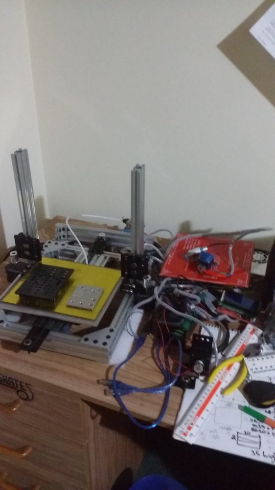
More updates soon...
the STD
Build in 'Cartesian Style Bots' published by Sam Dobbie, Oct 28, 2015.
A fully aluminium printer made from off the shelf components, no printed parts.
-
-
Build Author Sam Dobbie, Find all builds by Sam Dobbie
-
- Loading...
-
Build Details
- Build License:
-
- CC - Attribution NonCommercial - CC BY NC
Reason for this Build
I wanted to build a 3D printer, but didn't own or have access to one on which I could print the parts for one. I therefore decided to design and build one using only off the shelf aluminium components.Inspired by
-
Attached Files:

