
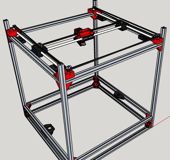
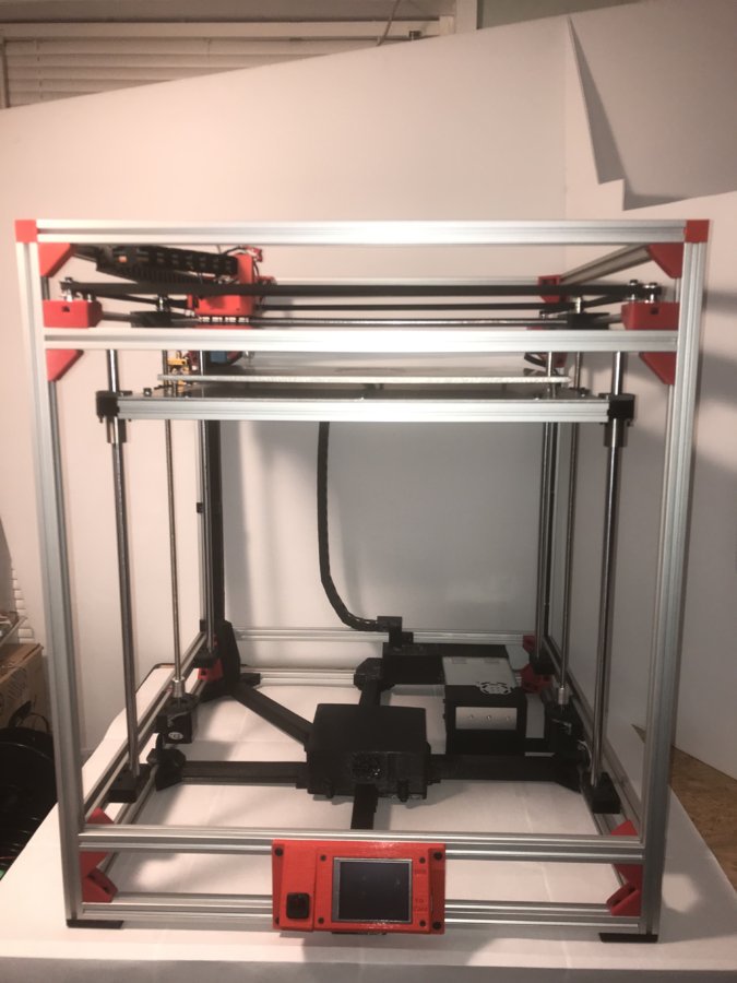
This is my first printer build and although it took me a year and a half, this printer is awesome. The Plastic Beast is a CoreXY printer and has a 440mm x 440mm x 440mm build area, and can print up to 600mm diagonally.
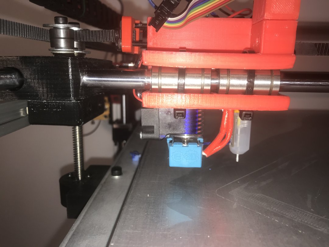
The Printer consist of a frame built out of 2020 Aluminum Extrusion Metal, MKS Sbase V1.3 controller and TFT32 Touch Screen. It has an E3D V6 Hotend and a BLTouch for auto bed leveling. I also designed a series of cable concealment brackets to conceal all of the wires and make it look neater.
I have included my Sketchup drawing, Bill of Materials, and a complete step by step tutorial with pictures. Every part on the drawing is 3D printable and ready for .stl export. This allows you to modify for your own equipment.
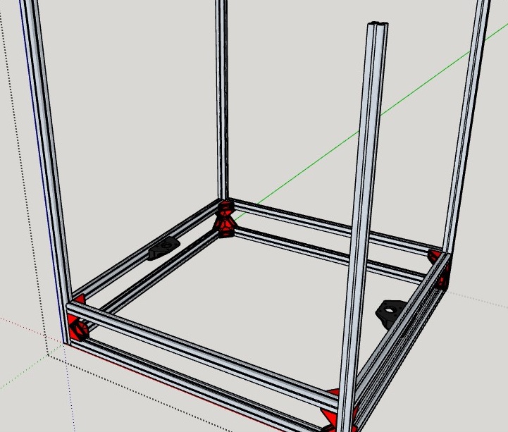
Step 1
Frame
Item Quantity
2020_3_Way_Corner 12
2020_2_Way_Corner 4
2020_Corner_Blanks 4
Z_Motor_Bracket 2
Z_12mm_Rod_Holder 8
Z_Top_Lead_Screw_Bracket 2
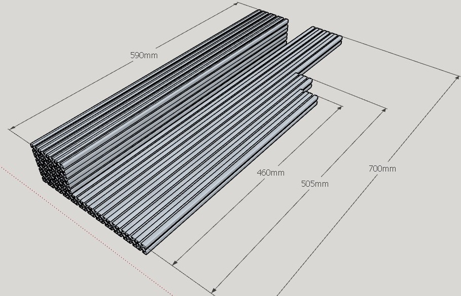
590mm 2020 Aluminum Extrusion 16
700mm 2020 Aluminum Extrusion 4
M5 x 10mm Socket head cap screw 122
M5 Drop In Extrusion T Nuts 92
M5 Extrusion T Nuts 30
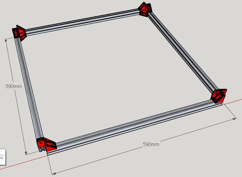
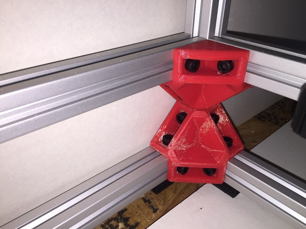
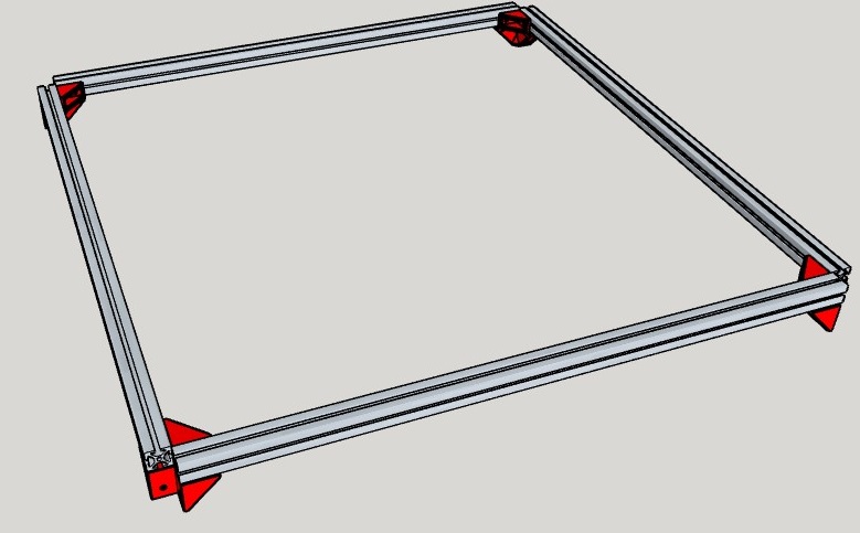
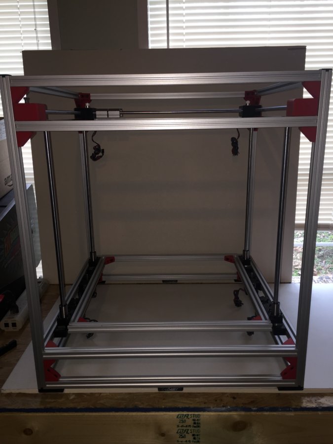
1. The first step assembling the frame is to make each of the 4 square sections at each level. When assembling each one, pay attention to the direction of corners. See the pictures below for reference. When tightening the screws, just get them snug at first because you’ll want to make sure the whole frame is square before you tighten them for good.
Bottom Level
Second Level
Third Level
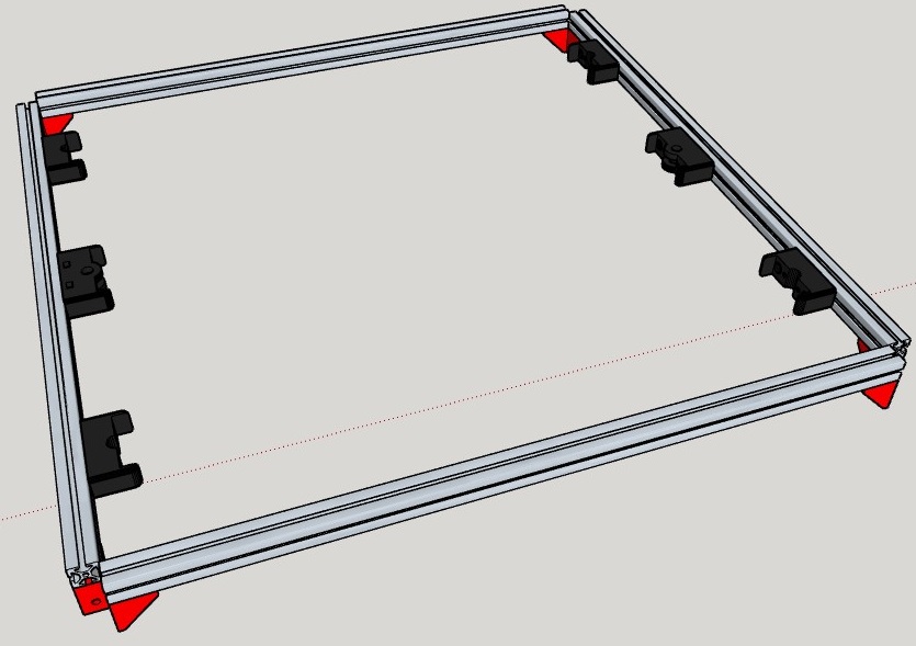
Top Level
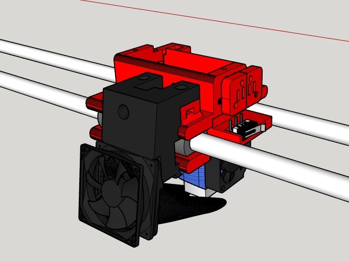
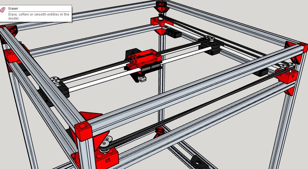
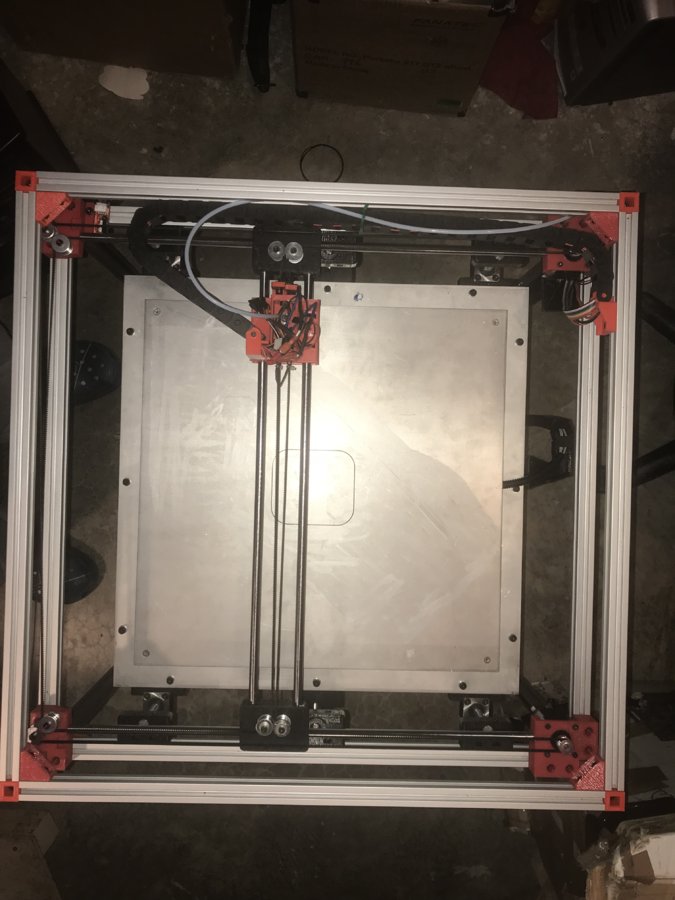
Step 2
XY Gantry
Item Quantity
XY_Idler_Right 1
XY_Idler_Left 1
XY_Motor_Right 1
XY_Motor_Left 1
XY_Carriage_E3D_V6_Bracket1 1
XY_Carriage_E3D_V6_Bracket2 1
XY_Carriage_E3D_V6_Lower 1
XY_Carriage_E3D_V6_Upper 1
GT2_Belt_Tensioner_Left 1
GT2_Belt_Tensioner_Right 1
HE_Duct_Fan 1
X_Endstop_Bracket 1
Y_Endstop_Bracket 1
X_Bracket_Left_Down 1
X_Bracket_Right_Down 1
X_Bracket_Left_Up 1
X_Bracket_Right_Up 1
537mm 10mm dia Y-Axis Smooth Rod 2
511mm 10mm dia X-Axis Smooth Rod 2
M5 x 10mm Socket head cap screw 14
M5 Extrusion T Nuts 14
M3 x 10mm Socket head cap screw 10
M3 x 20mm Socket head cap screw 24
M3 x 30mm Socket head cap screw 2
M3 Hex nuts 28
LM10UU for XY 8
GT2 Toothless Pulley 4mm Bore 8
GT2 Belts 5m & 2 Gt2 Pulleys 1
E3D v6 HotEnd, 1.75mm, Bowden add-on1
BLTouch 1
4010 Fan for Hotend Duct 1
End Stops (Only 2 are needed) 2
Nema 17 59 n-cm torque 2A 200 steps 2
M4 x 25mm Socket head cap screw 2
M4 x 30mm Socket head cap screw 2
M4 x 35mm Socket head cap screw 4
M4 Hex nut 8
2020_Center_Feet 4
2020_Corner_Blanks 4
2020_Corner_Feet 4
1. Take the Left and Right X Upper Brackets and put 3 or 4 M3 x 20mm Socket head cap screws through the holes and place upside down.
2. Place the 2 511mm 10mm dia. X-Axis Smooth Rod on the brackets with the 8 LM10UU bearings as shown.
3. Now place the Lower Left and Right X brackets on and secure with M3 hex nuts.
4. Install the rest of the screws and hex nuts and flip back over.
5. Install 4 4mm toothless GT2 pulleys with the 4 4mm x 30mm socket head cap screws, 4 M4 washers and 4 M4 hex nuts. You may need more washers for belt alignment.
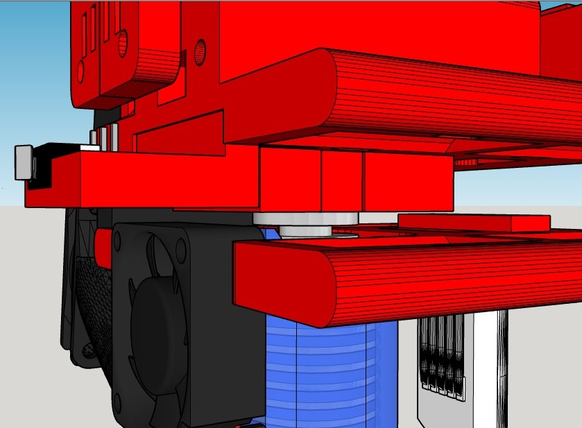
6. Install 2 E3D brackets around the E3D Hotend and secure with 2 M3 x 30mm socket head cap screws and hex nuts through brackets.
7. Install E3D and X endstop bracket to the upper XY Carriage with 3 M3 x 20mm socket head cap screws and hex nuts
8. Install BLTouch with 2 M3 x 10mm socket head cap screws and hex nuts into lower XY Carriage
9. Secure upper and lower XY Carriage brackets over the 4 bearings with 4 zip ties.
10. Install HE Duct fan with 2 M3 x 10mm socket head cap screws, and nuts.
11. Install 4010 Fan for Hotend Duct with 4 M3 x 20mm socket head cap screws and hex nuts.
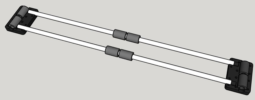
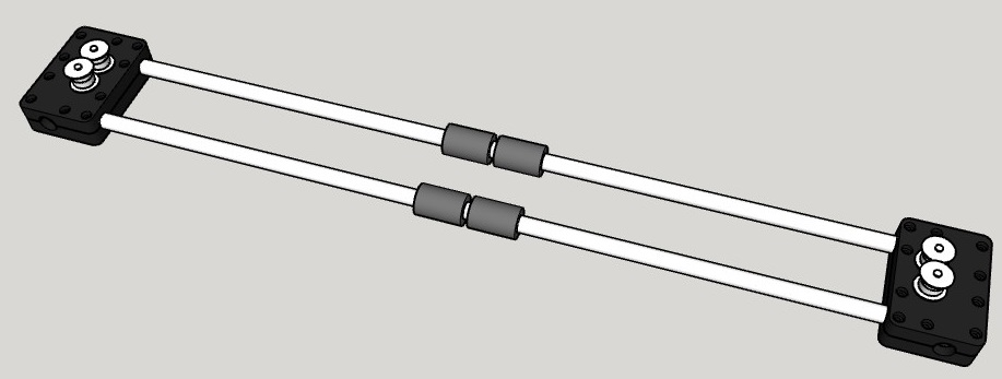
12. Now insert the 2 537mm 10mm dia. Y-Axis Smooth Rods into the Idler brackets on the right and left.
13. Slide the entire hotend assembly, rods, and bearings over rods you just inserted into the idler brackets.
14. Slide the other end of the rods into the Left and Right Motor Brackets until they are flush to the inside.
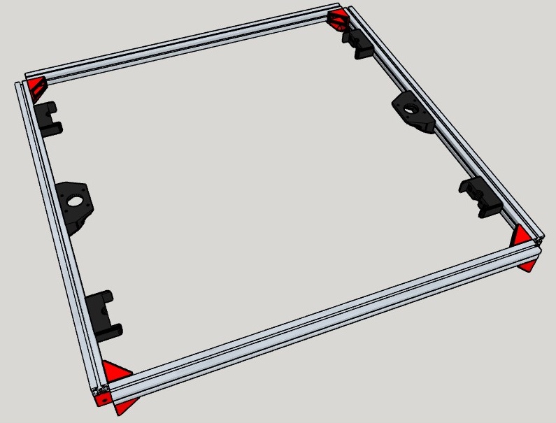
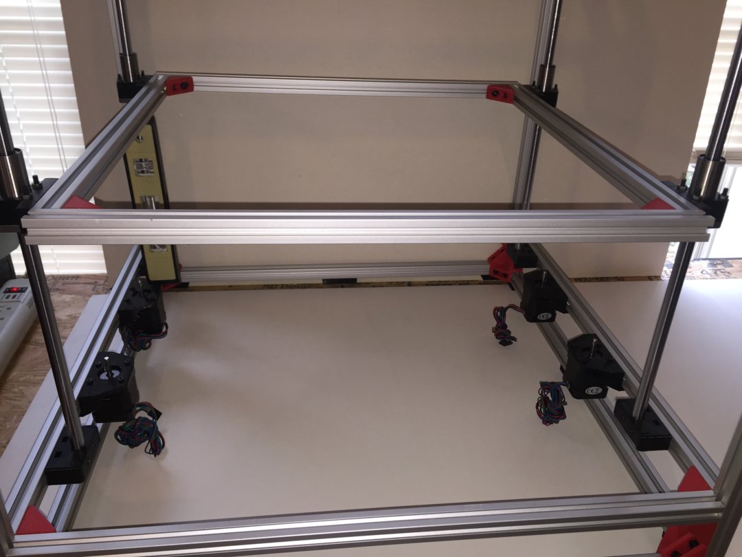
15. Mount the entire assembly to the top of the third level with 14 5mm x 10 socket head cap screw and extrusion T nuts.
16. Mount 2 Nema 17 motors with GT2 Pulleys to the brackets with 4 M3 x 10mm socket head cap screw each.
17. Install 2 GT2 Belts and secure with Belt tensioners and 4 M3 x 20mm socket head cap screws and nuts.
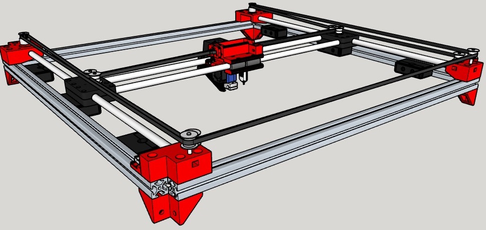
18. Install all four sections of the different levels to the 4 700mm 2020 extrusion pieces starting at the bottom. Once completely assembled, make sure it is squared and true and tighten all of the screws.
19. Flip upside down and install Center and Corner Feet with M5 x 10 socket head cap screws and extrusion T nuts.
20. Upright the assembly and install the Corner Blanks with M5 x 10 socket head cap screws. If you have an M5 tap it will make this easier.
Step 3
Hotbed Assembly
Item Quantity
2020_1_Way_Corner 4
460mm 2020 Aluminum Extrusion 2
505mm 2020 Aluminum Extrusion 2
M5 x 10mm Socket head cap screw 32
M5 Drop In Extrusion T Nuts 8
M5 Extrusion T Nuts 24
Aluminum Plate 505mm x 505mmx2mm1
Aluminum Plate 440mm x 440mmx5mm1
Z_Lead_Screw_Nut_Bracket 2
Z_LMK12LUU_Bracket 4
M4 x 25mm Socket head cap screw 24
M4 Hex nut 40
400*400mm 110V 600W Heat Bed 1
LMK12L for Z (LMK12LUU) 4
Copper Nuts 2
M4 x 30mm Flat Head Socket Cap 4
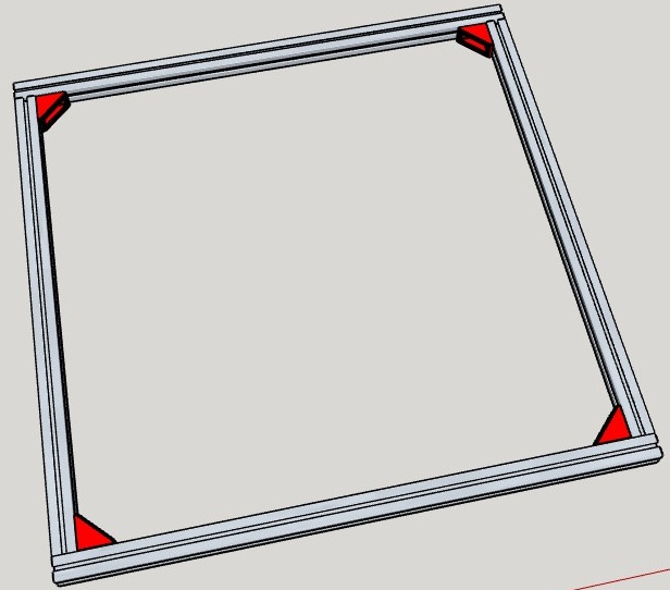
1. Build heat bed frame by joining the 4 pieces of 2020 extrusion metal that are left to make an even square with 4 2020 1 Way Corners, 8 M5 x 10mm socket head cap screws and 8 extrusion T nuts.
2. Attach the Z Axis Rod and Lead Screw Brackets as shown in the picture with 12 M5 x 10 socket head cap screws and 12 extrusion T nuts.
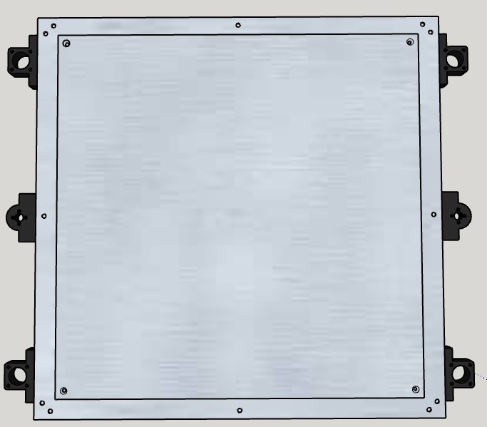
3. Attach 4 LMK12LUU bearings with 16 M4 x 25 socket head cap screws and 16 hex nuts to the bearing brackets.
4. Attach the 2 lead screw copper nuts with 8 M4 x 25 socket head cap screws and 8 hex nuts.
5. Attach the 3mm aluminum plate to the frame with 12 M5 x 10 socket head cap screws and 12 extrusion T nuts.
6. Mark the corners of the bottom of the 5mm plate at 400 mm square and attach the bed heater to the bottom by removing the paper backing.
7. Attach the 5mm aluminum plate to the 3mm aluminum plate using 4 M4 x 30 flat head socket screws and 16 hex nuts. Make it as level as possible with at least 15mm of clearance.
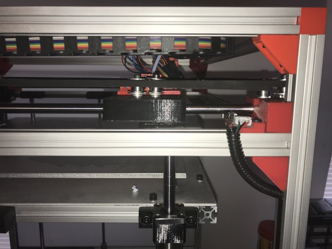
Step 4
Rod and Leadscrew installation
Item Quantity
541mm 12mm dia Z-Axis Smooth Rod 4
Z_12mm_Rod_Cap 8
Z_Top_Lead_Screw_Bracket_Cap 2
608zz Bearing 2
M4 x 25mm Socket head cap screw 16
M4 x 30mm Socket head cap screw 4
M4 Hex nut 20
M3 x 10 Socket head cap screws 8
Axis coupler 5mm to 8mm 2
Nema 17 59 n-cm torque 2A 200 steps 2
488mm Lead Screws 2
1. Attach 12mm smooth rods to bottom bracket of rod holder with the rod cap and 2 M4 x 25mm socket head cap screws and hex nuts. Allow the bottom of the rod to rest on the table so you can slide the heat bed bearings over the top. Repeat 3 more times.
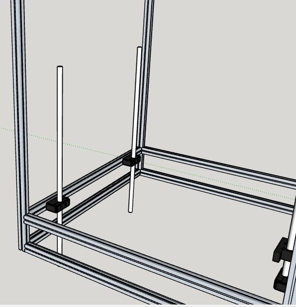
2. Slide heat bed onto smooth rods from the top.
3. Slide 12mm smooth rods up and into top bracket making sure it is even top and bottom and attach the 4 remains rod caps with 2 M4 x 25mm socket head cap screws and hex nuts in each.
4. Install 1 608zz bearing into the top lead screw bracket and install the bracket cap with 2 2 M4 x 30mm socket head cap screws and hex nuts. Repeat on the other side.
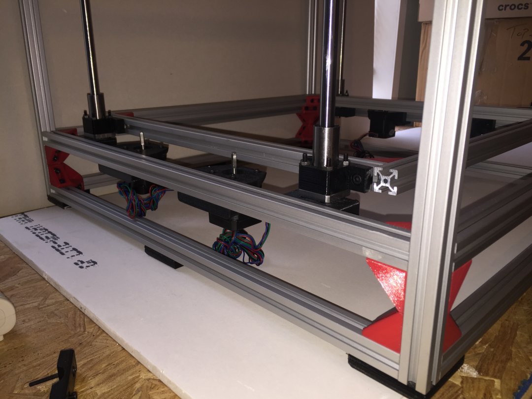
5. Install 2 Nema 17 motors into Z axis motor bracket with 8 M3 x 10 socket head cap screws.
6. Install the 2 5mm to 8mm couplers on to the 2 488mm lead screws and tighten. Thread the screws up through the bottom bracket and into the top one. Install bottom of coupler onto the motor making sure one of the small set screws is on the flat part of the motor shaft and tighten. There are many ways to do this process, just do what works for you.
7. Now you can go around and make sure everything is lined up, and moves freely, then tighten everything down checking once in a while to ensure it doesn’t get pulled out of alignment.
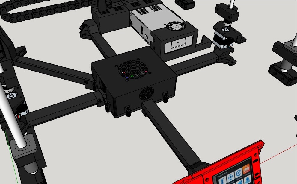
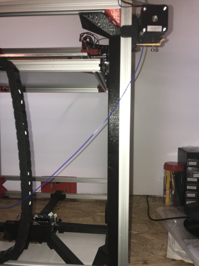
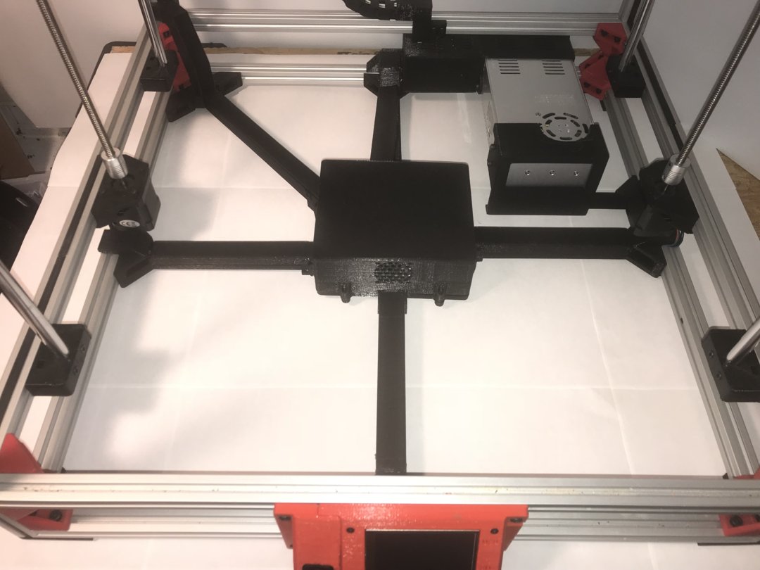
Step 5
Power Supply and Cable Concealment
Item Quantity
CC_Bottom_Corner_Bracket 1
CC_Corner_to_Center 1
CC_Front_to_Center 1
CC_Left_to_Center 1
CC_Rear_to_Center 1
CC_Right_to_Center 1
Power_Supply_Bracket_1 1
Power_Supply_Bracket_2 1
MKS_SBASE_v1_3_and_Wiring_Box 1
Solid_State_Box 1
360w 30a 12v Power Supply 1
M5 x 10mm Socket head cap screw 19
M5 Extrusion T Nuts 19
M4 x 6mm Socket head cap screw 8
M3 x 10mm Socket head cap screw 1
M3 x 14mm Socket head cap screw 4
M3 Hex nut 5
1. Attach Power Supply Bracket 1 and 2 to the power supply with 8 M4 x 6mm socket head cap screws.
2. Attach Power Supply Brackets to the frame in back right corner with 5 M5 x 10mm socket head cap screw and 5 M5 extrusion T nuts.
3. Install Solid State Box with 4 M5 x 10mm socket head cap screw and 4 M5 extrusion T nuts.
4. Install Bottom Corner Bracket into left rear corner with 2 M5 x 10mm socket head cap screws and 2 M5 extrusion T nuts.
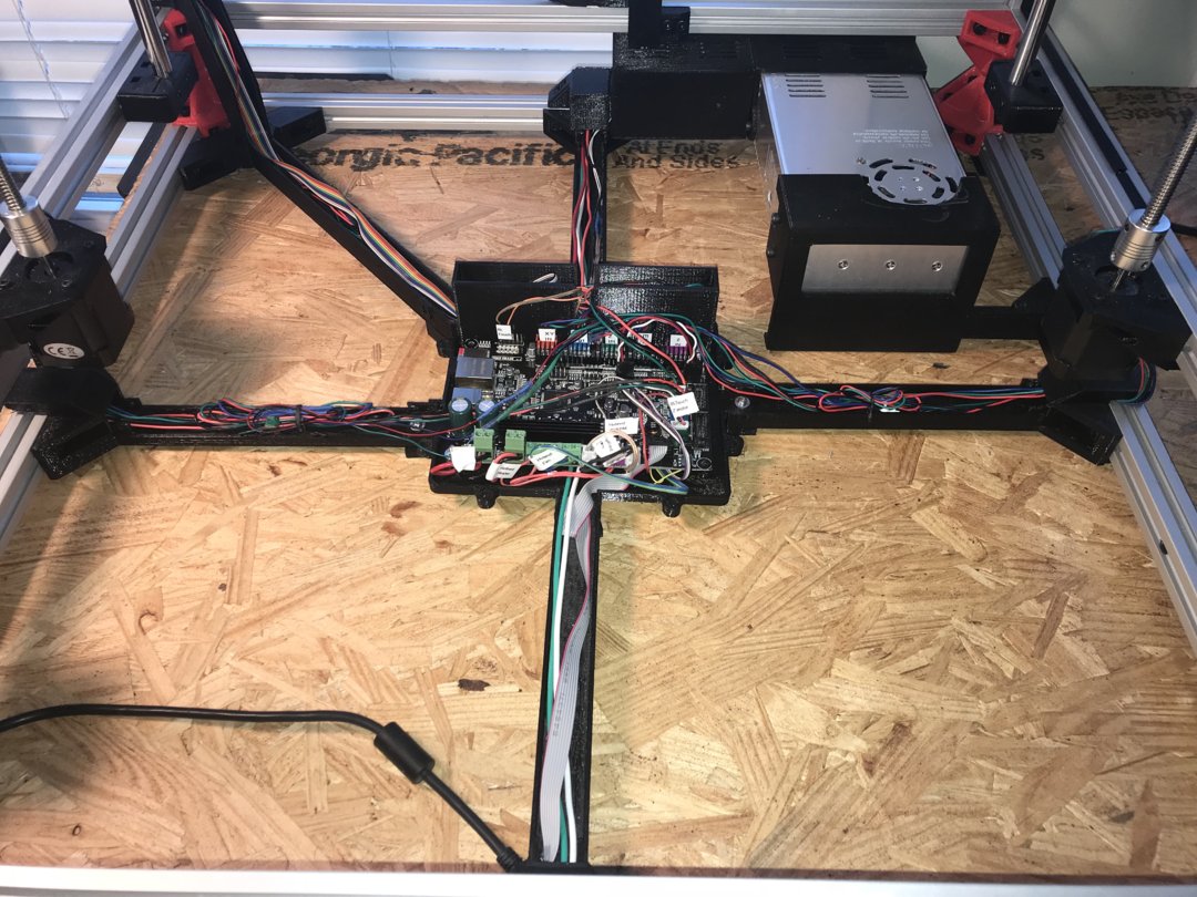
5. To make things much easier press all of the M3 hex nuts into the bottom of all of the Cable Concealment Brackets and the M4 Hex nuts into the center MKS Sbase box.
6. Set the MKS Sbase Box in the bottom center and start installing the Right, Left, Rear, Front, and Corner Cable Brackets into the 2020 Frame with 2 M5 x 10mm socket head cap screw and extrusion T nuts, and 1 M3 x 14mm socket head cap screw and hex nut per bracket. Attach the Corner to Center Bracket last.
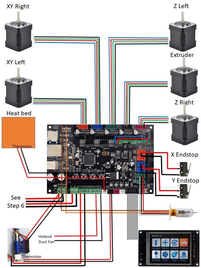
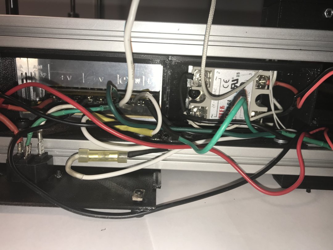
Step 6
Initial Wiring
Item Quantity
Rocker Switch 1
3 Prong Power Socket 1
18 Gauge Wire Assortment 1
SSR-25 DA Solid State Relay 1
TFT32_Bracket_with_Switch 1
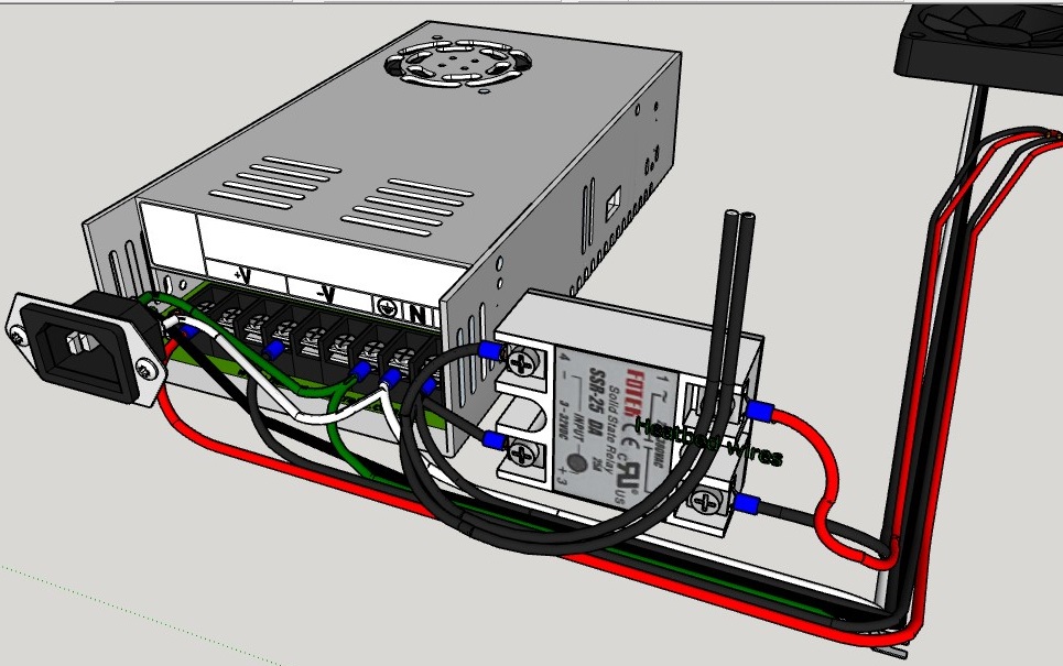
1. Mount the SSR-25 DA into the Solid State Box
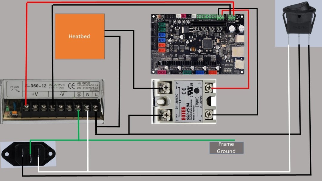
2. Wire power supply and relay according to the diagram and picture below using the 18 gauge wire and connectors.
3. Install Rocker Switch into TFT32 Bracket and hook up wires.
Step 7
MKS SBase v1.3 Wiring
Item Quantity
22 Gauge Wire Assortment 1
DuPont Crimping Tool 1
MKS TFT32 V3.0 Smart Touch Screen 1
MKS SBASE V1.3 Open Source Smoothieboard 1
2.54mm DuPont Connectors 1
TFT32_Bracket_Back 1
TFT32_Bracket_Main 1
M3 x 10mm Socket Head Cap Screw 4
M3 Hex Nut 4
Extruder_Motor_Bracket 1
MK8 Direct Drive Extruder 1
M5 x 10mm Socket Head Cap Screw 8
M3 x 10mm Socket Head Cap Screw 4
M5 Extrusion T Nuts 8
Nema 17 59 n-cm torque 2A 200 steps 1
1. Install MKS Sbase V1.3 into its bracket with 2 M3 x 20mm socket head cap screws and hex nuts.
2. Hook up main board power and heat bed wires to the MKS Sbase.
3. Install TFT32 into the TFT Bracket Main with 4 M3 x 10mm socket head cap screws and nuts.
4. Now attach the TFT32 Cable and stick it through the hole in the back plate, then attach the assembly to the frame with 4 M5 x 10mm socket head cap screws and 4 extrusion T nuts.
5. Put power wires through the hole in back plate, hook up to switch, and attach the switch and bracket to the frame with 2 M5 x 10mm socket head cap screws and extrusion T nuts. Slide against TFT32 Bracket.
6. Attach the other end of the TFT32 Cable to the MKS Sbase v1.3.
7. Install Nema 17 motor and MK8 Direct Drive Extruder onto the Extruder Bracket and mount to frame with 2 M5 x 10 socket head cap screws and extrusion T nuts.
8. Install the rest of the wiring following the diagram, some will need to be extended.
Step 8
Finish Assembly
Item Quantity
Solid_State_Box_Cover 1
XY_Carriage_Wiring_Cover 1
2020_Handle 2
CC_Bottom_Corner_Bracket_Cover 1
CC_Rear_to_Center_Cover2 1
CC_Corner_to_Center_Cover 1
CC_Front_to_Center_Cover 1
CC_Left_to_Center_Cover 1
CC_Lower__Bracket 1
CC_Rear_to_Center_Cover 1
CC_Right_to_Center_Cover 1
CC_Upper_Bracket 1
Drag_Chain_Bracket_HB 1
Drag_Chain_Bracket_HB_2 1
Drag_Chain_Bracket_HB_Cover 1
Drag_Chain_Guide 1
Drag_Chain_HE_Bracket 1
Drag_Chain_Link 60
HB_Drag_Chain_Bracket 1
HE_Rear_Drag_Chain_Bracket 1
M5 x 10mm Socket Head Cap Screw 17
M5 Extrusion T Nut 17
M4 x 12mm Socket Head Cap Screw 8
M4 x 25mm Socket Head Cap Screw 10
M4 Hex Nuts 18
PTFE Tube 1
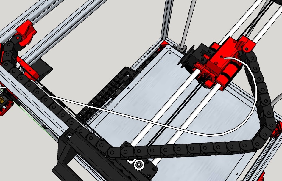
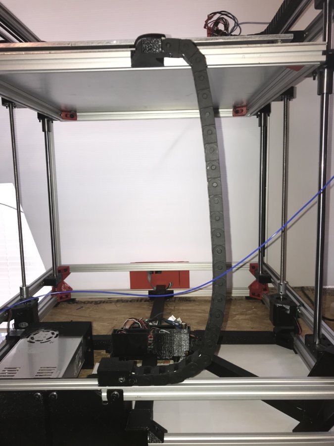
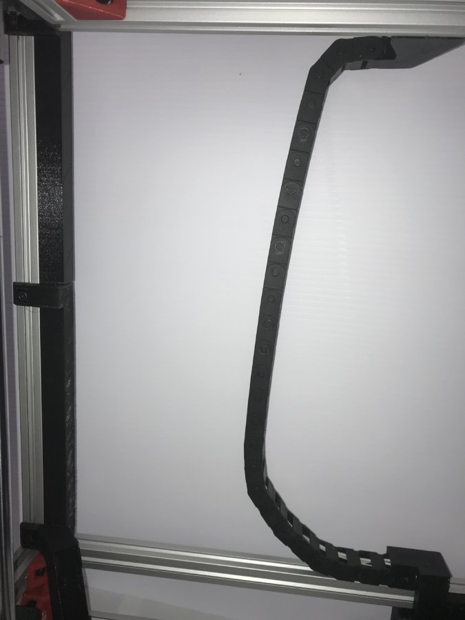
1. Install Drag Chain Brackets using 2 M5 x 10mm socket head cap screws and 2 extrusion T nuts in each bracket.
2. Connect 26 Drag Chain links for the heat bed and 34 for the hot end assembly and thread the wires through the drag chains.
3. Connect drag chains to drag chain brackets.
4. Install PTFE tube into E3D V6 and up through the XY Hot end Cable Cover.
5. Install XY Hot end Cable Cover with 2 M3 x 10mm socket head cap screws.
6. Once all wires are connected install all of the cable covers with M3 x 25mm socket head cap screws and M3 hex nuts.
7. Install power supply and SSR covers using 8 M5 x 10mm socket head cap screws and 8 M5 extrusion T nuts.
Step 9
Firmware Setup
1. Install drivers and firmware in accordance with MKS-SBASE Datasheet or visit the following website for more information. makerbase-mks (makerbase) · GitHub
2. Put the following information in your Gcode script for the BLTouch.
G91
G1 Z007
G90
M280 S10.6
M280 S7.0
G28
M280 S3.0
G32
G1 X225 Y200 F6000
G30 Z1.55 (This line could change due to your bed to BLTouch distance.
M280 S7
3. Load Filament and print a test cube.
Links
makerbase-mks (makerbase) · GitHub Makerbase Github page
Instructables - How to make anything How to information site
https://plus.google.com/communities/109126963511513081214 BLTouch information
Thingiverse - Digital Designs for Physical Objects 3D Models you can download
MyMiniFactory - Guaranteed 3D Printable Designs 3D Models you can download
start [Smoothieware] Firmware and Smoothieboard discussion
https://e3d-online.com/ E3D Hotend Information
http://reprap.org/ All things site for 3D printing
http://3dprintingforbeginners.com/ 3D Newcomer’s Forum
https://www.3dprintingforum.org/ 3D Printing Forum
https://www.sketchup.com/ Deisgn Software that’s easy to use
And of Course
https://openbuilds.com/ Open Source site “Dream it, Build it, Share it”

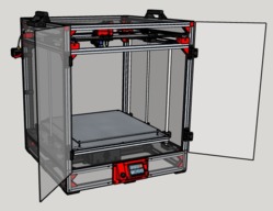
The Plastic Beast CoreXY Printer
Build in '3D PRINTER BUILDS' published by cdsmith12, Feb 28, 2018.
In my opinion, this is the easiest and most complete tutorial to walk you through building a large platform 3D printer and the Sketchup File is included for you to make any changes needed.. The Plastic Beast is a CoreXY Printer with a build platform of 440mm square. You can print 600mm or about 23 inches diagonal. Any level of user from novice to expert should gain something from my tutorial.
-
-
Build Author cdsmith12, Find all builds by cdsmith12
-
- Loading...
-
Build Details
- Build License:
-
- CC - Attribution - CC BY
Reason for this Build
I built this printer to have a larger build platform, and better quality than my Prusa i3 clone. I posted this build and wrote the tutorial so people that don't understand, can have a good guide written in a way that anyone can understand.Inspired by
Vulcaman, Vulcanus, Aldricnegrier -
Attached Files:
Parts list
-
Attached Files:
-

