
28/08/2016
This is my first build and I know Jack about CNC Machining/Routing.... So here we go !!
I have named this machine after the designer himself and in true Aussie tradition I have lengthened his name and added an "ie" on the end..... We also shorten names the same way here down under.
It's just something we do.
Firstly I did not purchase this as a kit, I decided to purchase it from the Bill of Materials and I purchased what I could locally here is Australia from www.makerstore.com.au and the balance from www.openbuilds.com
I slipped up on the order from openbuilds & only ordered 1 x 250mm C-Beam instead of 3 so I am short the two vertical pieces that hold up the Gantry.... Not a big deal as I have to place another order for the motors and some other bits anyhow and it has not stopped me getting on with the build.
Here I would like to share my findings/thoughts during the build and any pointers that might help somebody coming along after me, that like me is not real clued up on building mechanical things but I can hold my own and do things correctly when shown how.... My background is electronics/computers so I am hoping it gets easier for me after the mechanics are out of the way.
I started last Thursday night and assembled all my 30 little wheels kits, after getting saw thumbs, I was ready for bed so I packed it all up for another day, ended up using some board against a flat surface to make it a little easier on my hands.
The C-Beam arrived form the Openbuilds on Friday, which I might add was a very quick shipment, so very happy there with that, it was only 4 days longer than getting my other parts from MakerStore here in Australia.
During the last few weeks I was debating whether to go and purchase an Aluminium Cutting blade for my Compound Mitre Saw, Well I am so glad I did.... It makes the cutting of the C-Beam and V-Slot a breeze. Please make sure if you own a Mitre Saw or Compound Mitre Saw to cross check it for Squareness, do some test cuts and make sure it is true to square, this is extremely important especially when building something that requires precision like a router table. ALL Mitre Saws need to be set for squareness out of the box, so double check yours before using it for this task.
Moag points out the importance of squareness in the build instructions for this machine, do not overlook the advice, it really is very important.
Here are a few piccies of my saw and the blade I fitted, it cuts Aluminium beautifully and is just as nice as the factory cuts that ship from openbuilds, it has made the construction so much easier than using a hacksaw & file...... The thought of using a file scares me, although after a weekend of filing and you have mastered it, then I am sure it will work but it is definitely doing it the hard way.


The Caltex drum in the background is a drum of Kerosene that has been sitting here for at least 17 years, it was left at the house from the previous owner, so who knows how old it really is.
I decided to buy a nice set of M5 x 0.8 Taps, I already had some cheap Tap kits but they were all the crap made Chinese ones, I could just see the one and only M5 in the kit breaking and to be honest to do the tapping job properly you really should a have a set of three taps on hand for the thread you are doing. 1 x Taper, 1 x Intermediate and 1 x Plug.
The Taper Tap is the magic one that gets you square into the hole and is the best selection for starting a new thread, it pretty much looks after the squareness for you and you are on your way.
The Plug Tap is the one to get the thread right to the bottom of a hole, whilst you can use this Tap to start a thread it is easy to go into the hole off square.
Here is a picture of what these three taps look like and then it will make sense for somebody doing this for the first time. I purchased a set from RS-Components P/N 215-574.
You can see the quality straight away, they are marked HSS which I think means they are made from High Speed Steel.


You can see a Jug of Kerosene here I used for Lubrication for the thread cutting, I used the wire wheel to clean the chaff out of the tool between holes as I did not have wire brush handy, I also used high pressure air to blow away the chaff from the hole and tool so it was nice and clean for the next thread. Be sure to use goggles and exercise all safe practises, you don't want to get any small pieces of metal in your eye.
Thanks to Moag with his advice in the build manual I finally used my >17 Year old drum of Kero, and Tapped all my holes without incident, the lubrication trick definitely works as my experience with tapping holes over the years has never been a lot of fun.... When it goes bad..... It is very very bad and wastes a lot of time, not to mention destroying the material you are working on by the time you dig a broken Tap out.
Here is the method I used to tap my holes, apply some kerosene to the hole, also dip the Tap into the Kerosene, start screwing into the whole half turn at a time, then backing off a quarter turn, do this repeatedly until you are all the way down. If you feel the tool binding, do not panic just turn back in the opposite direction a quarter turn, keep going back and forth until it is free again, the idea behind the backing off is to allow the chaff that is cut away to move into the slots or flutes that are cut along the side of the Tap, the cut material has to go somewhere or the tool would just bind up and break if those little slots did not take the excess material away.
Also use the back and forth action when exiting the whole too until you are all the way out.
I cut the thread 20mm deep in my holes just in case I strip the thread by accident there will be some more thread in there I can pickup with a longer screw, All the screws are only screwing in 10mm as per Moag's design, so this is just a little safety net.
One major piece of advice I would give when cutting threads is "Just don't rush".
I did get a bit of a saw wrist from the thread cutting but I have a really nice and perfectly Square base so I am Very happy, this should make it all go together nicely.
I have to say the Build Manual is excellent, and I have even been able to jump between different sections very easily as I am missing the Gantry supports and could not complete some of the sub assembly's properly but it really has not been a problem. I really like the way it has been broken down into smaller tasks/builds and then comes together to make a bigger component... Extremely well written and thought out, thats for sure... My hat is off to you Craig... Really nice job.
I will update this as I move further through the build but at this stage I am very happy with everything so far.


Cheers Glenn.
05/09/2016
OK well much has happened since I started the build.
One thing that has been quite a good experience was watching Brady do the Live build over on Twitch, however I was not able to join in during the live feed due to time difference so I had to watch them all after the event, it certainly is handy seeing somebody else build the unit before you do and to see the little issues that you may strike or run into.
I have assembled all my Gantry plates and attached the wheels and got to have a feel of the eccentric adjustments and how the assemblies run on the C-Beam, they really feel great and the adjustments for the wheel pre-load was reasonably easy.


I was not aware of how tight or smooth they should run along the rail and thankfully watching Brady's broadcast on his twitch channel, I saw that one of the builders on chat said that holding the beam close to a 45 Degree angle the Gantry should run down the rail easily under gravity, so I adjusted the wheel tension using that method, which seems to work really well as general guide.
I also found that I had the same problem as Brady did with the nut blocks binding on one of the Y Actuators and I could not figure out how to fix it, I just put it aside to deal with later and then whilst watching Brady doing his actuators the same night I could not believe that he struck my exact issue also, and he came up with the fix which got me sorted out.
I still have not had an answer to the Question of why is there a different anti-backlash system used for the X/Y Gantry's as compared to the Z Gantry, there must be some technical reason but neither Craig nor Mark have given any explanation on this, I was just curious about it and not the only one to ask the question either. So if somebody could answer that question I would be interested to know.
I purchased some Dry PTFE Lubricant from Bunnings here in Australia, to lubricate the Lead Screws and Nut blocks, that works great and I think is important, probably wouldn't hurt as a regular maintenance routine either I would say.
I was getting really excited now as I was going to see how the mechanism worked with the lead screw fitted but my bubble was burst very quickly when I realised the Lead Screws supplied from makerstore.com.au are the incorrect size, the Y Axis (500mm) are 20mm too short and the X Axis (1000mm) was 32mm too short.
I have confirmed with Openbuilds that ALL their Lead Screws are 40mm greater than the nominal size listed on the web site, so:
250mm is actually 290mm
500mm is actually 540mm
1000mm is actually 1040mm
I made an assumption that Makerstore.com.au would cut their lead screws the same lengths as Openbuilds and of coarse they don't, Openbuilds allow for the two 12mm thick endplates at either end of the C-Beam whereas Makerstore do not stock C-Beam or the endplates and only stock V-Slot Rail and use very thin end plates on their actuators meaning they then supply shorter lead screws, so this is something to be very mindful of if you do what I did and order parts from different suppliers.
Below you can see from these pictures that the Lead Screw for the 1000mm Length here was 32mm too short. I ended up cutting this one down to 540mm to use for one of the Y Axes and I re-ordered from Openbuilds to make sure I got the correct lengths.


Double check the exact lead screw lengths that will be supplied to make sure they will suit your build, or make sure you order them much longer and cut them down yourself. I am now trying to get hold of Steve from the Makerstore to see if he can help me out..... This is proving to be difficult and is now starting to frustrate me as he does not answer his phone or return calls if you leave a message. Admittedly I have not emailed him yet but that will be the next step, It would just have been nice to discuss the issue with him to get a quick answer and see what could be done.
By the way the Z Axis is OK because I ordered a 300mm length for that one because 250mm is not listed on the makerstore site. The build calls for a 250mm which from Openbuild's would be 290mm, so this one I can trim down and make it work.
I also ran just short of M5 Nylock nuts for some reason so the BOM may be slightly incorrect for the Nylocks, that is not a big deal as a quick run to Bunnings got me a few extra's.
So I will give it to the end of the week for Steve to contact me and I will shoot off an Email to see if he can sort the lead screws out otherwise I will be back to Openbuilds with my second order of Bits and then I should have it assembled after the next shipment.
In the meantime I decided to start working on the MDF Table, so I decided to go down the hardware & pickup some MDF sheet to make the table base & spoil boards.
I trimmed the boards down to size using a Table saw & basically followed the exact procedure in the construction guide, Used some glue and clamps for the table base. I May look at replacing that with a plate of Aluminium down the track but the MDF will be fine for now.


I have now mounted and squared up the MDF table base and spoil board as per the build manual, that all went pretty much to plan. I have now mounted the base board to the Y Gantries and it moves beautifully but unfortunately no Lead screws fitted at this point, very frustrated with makerstore.com.au, I just cannot get a quick answer from Steve.

So far the build has been fairly easy and the Manual pretty much covers it all very well.
25/09/16
Well I Placed my order last week for new Lead Screws and the 250mm C-Beams I had missed on the first order, I also missed the 8mm shims for the Lead screws too (DOH !!).
While I was at it I decided on a few extra bits, I grabbed a bundle of drop in T Nuts (Should come in handy), a bundle of Slot Covers/Panel Holders (to give it a finished look and keep cables tidy/hidden) and some slot mountable door handles.
I am going to put some handles on the side of this thing as it is just that little bit awkward to handle and it will certainly have a bit of weight in it so the handles should help out when wanting to move it around.
The order once again arrived within about a week here in Australia, so no complaints about delivery times to OZ that's for sure. Upon checking/inspecting the shipment I noticed that one of my motors felt extremely hard to turn, in fact I had to use a pair of bull nose pliers to turn the shaft, the other three motors moved freely with just my fingers. I also noticed the shaft of the faulty motor was displaced by about 10mm, so it looked like it was damaged. I could not see any damage to the packaging so I presume it was a manufacturing fault and I would say Openbuilds store probably would not have even know it was like this as it had not been opened previously.
Here you can see the shaft displacement compared to the other motors.


Anyhow a quick PM to Mark Carew to enquire about how to do a warranty claim and the parts team had a new motor shipped out with a shipping confirmation all within the hour.... I nearly fell off my chair as this was totally unexpected, they did not require me to ship the faulty motor back so there was no extra cost for me at all.
On op of that I received the new motor within 6 days including the weekend, so it looks like they sent that out on Priority Mail shipment.
Thankyou to Mark and the Team at Openbuilds, this truly is what service is about and gives me great confidence in any future purchases from the Openbuilds store.
Well it didn't hold me up too much as I am just taking my time with the build, doing a little bit each night. So I got the Lead Screws in and finally got to see the actuator in action !!
I even attached a cordless screwdriver to the shaft coupler and gave it a run back and forth being careful not to run it to the limits, I entertained myself for the rest of the night with these actuators and it really felt like a great sense of achievement seeing them in action.

The next day I put the cordless screwdriver away and thought I better get this thing together.... So off I went. I mounted up the vertical C-Beams for the X Gantry and squared them up.
Mounted up the X Gantry itself to take an overall look at the machine, here you can see I have also mounted the door handles on the side V-Slot Rails.


Here it is with the table remounted & lead screws in place.
At this point it starts to hit home that you are pretty close to having your own CNC in the back shed and you can't stop looking at it and admiring the bundle of parts that you have put together that has now become a real machine, it really is quite a satisfying feeling.


I then proceeded to mount the motors and that all went together as planned, and was as per the instructions.


That is it for now, I am now waiting on some electronics to arrive and while I am waiting I will purchase a Makita RT0700 Locally and work out a mounting adaptor/converter for the Openbuilds spindle mount.
03/10/16
OK So I went and purchased the RT0700 Makita Trim router from Bunnings here in OZ, It was $197.00 AUD and was just the basic kit in a little metal carry case, I thought about buying a few accessories for it but it is mainly for the CNC so if I upgrade to a proper spindle later then I will go and grab the accessories so it will be usable for other tasks.
The first problem is it does not fit in the standard open builds spindle mount which I was well aware of, so a bit of measuring and googling I decided to give a piece of 65mm PVC Water (Pressure Rated) pipe a go as somebody mentioned that it would work well, and it does, the only thing you need to do is cut a slit in the side of the small offcut of pipe and you are in business. I was going to get all fancy and hand route an adaptor but there is no need.
What I will do is use the PVC Pipe adaptor to get the router functional and then cut out a proper adaptor on the CNC, firstly out of MDF and then out of Aluminium once I get up to speed and capability. I just love how this thing will be able to make parts for itself !!!
Here is the pipe I used.....

I simply cut off a piece at about 30mm in length and then cut a slit down the side so it would fit around the router, I used my mitre saw but a hack saw will do just fine.
Here it is with the Makita firmly mounted, it seems to hold it really well and I don't think there will be any problems and should get me cutting to produce some parts.

09/10/16
Well my DQ542MA's turned up, in the kit there was a Free Parallel Break Out Board (BOB).
I had also ordered a CNC Shield intending to run GRBL as I have already loaded an UNO with it because I am reasonably experienced with Arduino programming and already had Arduino UNO's laying around in the workshop here, it was fairly easy to get loaded & I could see that it was working fine.
However the BOB was a challenge as I had never seen one or used one before and have always seen people talking about them with wiring diagrams etc. I also at some point wanted to play with MACH3 and because MACH3 directly supports Parallel ports I thought, "why not give it a shot", as I now have everything I need to give it a try.
This lead me to having a serious think about my controller box and what to do and how to build it.
I have old PC's and cases laying around in the workshop here so I got to work and decided there is plenty of room in a standard PC case to mount everything in there, the PC case will also nicely supply 12V and 5V required for other things.
I also ordered a dedicated power supply to supply the controllers/Motors.
Because I will be running 4 x High Torque NEMA23's rated at 3 Amps Peak the minimum requirement for the power supply will be 12 Amp so I went with 48V 15Amp (720 Watt) unit, it also has adjustable voltage output and can be set from 36V to 50V..... This is important as the GRBL shields will not go above 36V, this will allow me to play with GRBL too without changing power supplies. I have fired up the PSU and it is settable to the voltages advertised with a multi turn trim pot and seems very stable too, I left it running at 48.00V for several hours with no load and she didn't drift at all. I will be using 48 Volts with the BOB and MACH3 at this stage.
So here is some of my handy work on the PC that is going to host all the electronics for the Mill.
The DQ542's Fit beautifully mounted Vertically in 3 x 5.25 Drive bays, so I removed the ATX case faceplate and proceeded to make up a mounting system for the controllers. I modified the case itself and then found a piece of Aluminium angle I had laying around for the mounting system.
Here are some pics....


I mounted the Aluminium Angle into the drive bay as shown.

I then got the required hole placement by fitting the controllers in there with the case sitting on it's bum, I used some standard PC screws for mounting them, some PC screws have a Tapered thread that will self tap into soft/thin metal so I drilled the holes small enough to self tap with those screws.
Here they are firmly mounted, Mounting these controllers vertically is advantageous, as the cooling fins on the heat sinks will be vertical creating natural convection for cooling, I will however probably add some extra cooling fans but I will see how she runs and monitor the heat build up in the case carefully, there is going to be a lot going on in there and the heat will certainly be much greater than a standard PC.

Next I mounted the BOB, and would you believe I didn't even have to drill any holes, the mounting holes on the BOB lined up perfectly with the Hard drive mounting holes on the case.... What Luck !!


Here is a pic of the Power Supply mounted in the bottom of the case, there was just enough room, I do lose the use of those PCI Slots but I should not need them anyhow.

Here it all is ready for wiring.

So I need to get some wiring done to do a little test with MACH3....
I am off to do some study because I am noticing peoples wiring diagrams are not consistent with these BOB's and I think it relates to MACH3 being very customisable when it comes to the signalling on the Parallel Port.
I have also got some more hardware to start wiring the Mill itself, I plan to put connectors on the Mill so it can be disconnected easily from the PC, I have also purchased the plastic slot covers to keep the wiring tidy and some drag chain..... So there is plenty to do, but I am very keen to get some motor movement happening and I think I might start on the PC side of things first to prove the BOB and Controllers are working.
I need to load up Windows too, will be sticking to 32Bit Win7 for the OS.
Cheers Glenn.
16/10/16
Today I fitted up some Strip LED's, I gotta make this little puppy sexy so it looks good for my friends... So Strip LED's are a must, it will also be a good indication that power is ON !!
Anyhow I just had to power them up to see what it looks like so I ran a little 12V Power supply down to the workshop and connected some alligator clips.... Time to update my Build photo !!

Here is a look from the underside.

Cheers Glenn.
17/10/16
I have now started the wiring and thinking about cabling/Connectors.
I Installed the drag chain on the X Axis as you can see here in the next photos.
I cut a small piece of 50mm Aluminium Angle and used some left over spacers from the build to setup a mounting point on the Z Gantry for the drag chain, the Actuator end plates already have some M5 tapped holes in the bottom of them, so I took advantage of them to mount the Angle plate.


I wanted to be able to conveniently disconnect the table completely at any time so I did not want to hard wire the motors etc. So I purchased some 4 Pin Mic connectors and using some more 50mm Aluminium Angle prepared a connector mounting plate to which I can mount all all connections to the Mill.
This plate will house the Stepper Connectors, a DB9 Connector that will carry low power 12V and 5V and End stop signalling. I will also be mounting an IEC socket to handle the 240VAC to the Makita Router. I will be grounding the table via the IEC Wiring which I think is an extremely important safety point you should not overlook. The Makita router is double insulated and does not carry a ground wire in it's cable. I will be disconnecting the original cable form the router and replacing it with a short length of mains cable with an IEC Plug on it, the ground wire will not be terminated in the router itself and the router will remain double insulated but the the ground cable from the mains will be terminated onto the Connector plate on the Mill effectively grounding the chassis.
I will basically have an IEC extension cable that is permanently mounted in the drag chain and this will allow me to easily disconnect the router from the table.
Here is a picture of the connector plate cut and filed (De-burred) and mounted in position with some drop in T-Nuts.

As you can see I purchased some cable tie mounts too so I will have something to tie the cables down to. All cabling comes to the right hand side of the machine, this was planned during the build.


You can see here in the above shots how I am using the slot covers for cable routing and trying to keep it nice and tidy.
I extended some of the Stepper motor cables that needed extending and cut back the ones that had too much length and started cable tying the looms so they won't catch on anything.


I got too excited and had to throw some connectors onto the motors for some testing, and managed to get my table to successfully move in all axis...... I will embarrassingly admit that in the excitement and playing around in the motor tuning section in MACH3 I did crash the Y axis into the end stops.
Some advice for people that reach this point, before getting carried away, GO AND SETUP THE SOFT LIMITS AND ACTIVATE THEM FIRST, I should have RTFM first but I guess that's how you learn what not to do !!
Anyhow no damage was done thankfully.

Below you can see the Router IEC Pig tail that will be terminated into the router.

20/10/16
It was now time to try and get some pen markings onto paper, so I started building a pen adapter for the standard Openbuilds router mount. I just used some of the offcuts of the MDF that was used to make the table base and I used a good old hole saw to cut out the adapter ring..... Vicious old things those hole saws but it did the trick.


I cut the center hole to accept 20mm Conduit with a nice tight fit.
The actual pen adapter will be very experimental but I plan to have it spring loaded so as to keep pressure against the paper and allowing for slight surface variations, the trick will be making the pen holder able to slide up and down but also to be rigid in the horizontal plane, otherwise the drawings will turnout pretty crap if the pen can wobble around even just half a millimeter.

I will come back to my Pen adapter as it is going to take some trial and error and some experimentation but I will post my final design here and promise it will not be very expensive to make.
After Jogging my brains out and loading a few dry runs of the road runner sample G-Code supplied with MACH3, I decided to get back to work and get this connector plate sorted out.
Well I avoided filing most of the build but not this time, however I managed to keep it to a minimum... I hate filing, it's one of those jobs you usually get apprentices (Juniors) to do... You know how it is !!

I cheated on the round holes cause I am not an apprentice, I used a knockout punch that I have owned since my days of being an Apprentice, it's a rusty old piece of kit as it got some moisture in it years ago, but still works like a charm, I have not used it for years. It's basically a cutting Die and great for panel work when you need to cut relatively large holes in metal to mount things that are bigger than your standard set of high speed metal drills.
Here is what a knockout punch Die set looks like.
You can see here a piece of the Aluminium still in the die I just removed from one of the holes.

Oh and the square hole for the IEC connector .... Well I cheated on that too, I got out my trusty new Dremel and cut most of it out with that, I only filed the last half a millimeter or so to square it up and allow the connector to fit in.
The DB9 connector I was not so lucky due to the odd shape, I drilled a few holes with high speed drill bits, cut out what I could with the Dremel and the rest was filing, Geese a Router/Mill would have been handy for this plate LOL.

I ran Taps down through the small holes so they are threaded and I can then mount the connectors straight onto the plate without using nuts and washers.
I gave it a bit of a make over with some wet and dry fine sandpaper and she came up pretty nice.


The above picture shows the Mains ground Terminal fitted.
More updates to follow, I am currently preparing a Tool Trolley that I just purchased that will house the Mill and all associated tools and bits and pieces that go with it including PC and screen.
Cheers Glenn.
29/10/16
Well a Change of pace, I kept myself amused this week with the Tool trolley that will host the CNC Machine. I got a bargain, we have an outlet here in Australia going bust and they are selling out all their stock, a company called MASTERS owned by Woolworths. Anyhow I went sniffing for a bargain and I think I did ok on this lot.
Picked up the Tool Trolley for $488.00 Australian
Picked up the Pine board and a Piece of 16mm MDF required as a spacer to fill the recess for the top of the Trolley for $30.00 Australian, I also grabbed some L brackets for the Pine Board overhang to give it some extra strength, can't remember the price on those but they were only a few dollars.
Fitted up the brackets and trimmed the MDF for a nice snug fit, mounted the Pine Board on top and decided to give the trim router a run and took off the fairly sharp square edge on the pine board with a V Bit, what a nice little router... It works great.
I spent the next few nights sanding and lacquering the pine top, I decided I better seal it because of possible oil and other substances that it will most likely get exposed to. The whole thing came up fantastic and ready for a nice new Mill to plonk on top.
Here is how it came out:

Here is a Pic of the L Brackets I fitted up.

In between all that I was messing with this CNC Pen again, have not perfected it yet.
Here are some pen plots, am having a bit of trouble getting good plots but am very sure it's all software/settings related. Have notice that MACH3 is very susceptible to being interrupted even when zooming in and out with the mouse on the Tool Path Screen. I am running it under Windows 7 and have read people moving back to Windows XP where it works great, so I might give that a try next.
I have multiple problems, there is lateral wobble in the pen and MACH3 is Drunk, Well that's how @Moag described it in my forum thread, I love basic Technical descriptions like that.
In between all these plots I was messing around with speeds and accelerations and not really making any notes of my exact settings over a Beer... Just playing around, the CNC and I were getting drunk together !!


In the end I did manage to achieve this next plot, so I think I am slowly getting there and need to take a more liberal approach to settings and change things more systematically, it's not a good idea to change too many things while you are learning.

This looks pretty right except you can see the pen wobble on the little circles.
05/11/16
OK Back to the build, Well it's now time to try and get this thing to what I would call a finished state.
I want to fit up Limit Switches and allow for a Touch Plate facility.
I am going to attempt to use Hall Effect Switches, Jaycar Electronics here in Australia sell a pre-built board for $5.00 Australian, Even if the whole thing doesn't work out it will not be a lot of money wasted.
Now if your looking for a good source of Shielded Multi-Core Cable, Namely 4 Conductors + Shield look no further than your box of cables in the garage or the cable draw in your spare room with all those USB cables that you have never used in your life.
All USB Cables have 4 Cores with Shield and for a small Mill Project like the C-Beam XLarge they are pretty much just the right length for the job of Limit and Touch Sensor signalling.
By the way each run will have a single spare core for later use, I will most likely use one of those extra cores on the Z Axis sensor runs for a Touch Plate setup.
So I purchased the Hall effect sensors for $30.00 Australian, in fact a little less as they were $4.95 each, that gave me six sensors.
Now the magnets, these can be quite expensive but there is a good source for those too, I have literally hundreds of them laying around here from old jobs.
If you can get your hands on some old Hard Disk Drives, 3.5" or 2.5" will do, rip them apart and you will find two perfect beautiful neodymium magnets surrounding the Head Assy. They are usually glued in place to the surrounding metal case but if you grab some pliers and simply bend the metal housing they will come away nicely and you have then got some strong little magnets to play with, by the way make sure the Hard Disk drive does not contain any data that you need before you start ripping it apart... This will be a one way street and there is no turning back !!
Here is what the inside of a drive looks like, this is 2.5" Unit.

The Head assy is located to the bottom right of the drive in this picture, you can see that I have already removed the assy and extracted the magnets, the platter makes for a really nice mirror too, could be fun to do some decorative engraving on the platter and make some nice coasters.
Here is what you are looking for..... neodymium magnets !!

The one on the top is from a 2.5" Drive, the bottom is from a 3.5" Drive.
I used both types just due to the physical sizes suited well.
By the way it is very dangerous to attempt to drill or cut these magnets, they can catch fire from the heat generated by the friction, if they burn the heat is extremely intense. They have the properties of ceramics, so they are hard to drill anyway, the best thing to do is use them as they are and DO NOT attempt to modify them. I believe the particles can also present health risks to, as long as they are a whole unit you are safe.
Do a Google on the subject to find out more.
So I then came up with a mounting plan for the magnets and sensors, this is going to be experimental as I am not sure if its all going to work, but if they do I will probably mill a better mounting system for the sensors.
For the moment I am just using PVC Angle for the sensor mountings, However to mount the Magnets I decided I wanted to utilise existing screws on the system with some Aluminium Bar and Angle, I wanted the Magnets to be mounted by screws and not glued to be sure they don't fall off accidently.
Here are the Hall effect sensors from Jaycar Electronics, I have also seen these on Ebay.

I used Aluminium Bar and Angle and more filing to make a mounting system for the Magnets.
Some tips and tricks for metal work for those who have never tackled a project like this before.
Always wear eye protection (NUMBER 1 PRIORITY)
Always use a centre punch to get accurate drill placement.
When drilling larger holes, make a pilot hole first with a small drill, and then move up in size to make the larger holes to the size you want. It may seem like a lot more work but your hole will be in the spot you intended and not 1 or 2 mm out. If you start with a larger drill first up, it has more tendency to wander.
Have a good set of files ready, including large and micro files.
A set of Reamers to make hole larger can be very handy too.
A Dremel style tool can be of great assistance too.
A Mill would be even handier !!
Here is some more of my Aluminium handy work.


Here are the Magnets Mounted, as you can see I needed to get the mounting holes positioned pretty accurately here, the good old centre punch is your best friend. I tapped the holes and used regular computer case type screws.


So here is my first "Moagie Mill" Modification.


Here are the PVC Mounts for the Sensors, they will do for now for testing and I will improve the mount at a later date, hopefully these things test well.
Something I underestimated was getting more cable up through the Drag Chain... what a pain in the BUTT !!
But I have managed to get all the sensor cabling in place and it is ready for the final wiring stages now.


OPENBUILDS WAS HERE !!

Here is the rats nest of Cables I am faced with at the Connector Plate....

Well that's it for the moment, next to do is finish up on the sensor wiring, I will most likely move the Mill down to the Garage and mount it down onto the Tool Trolley, I don't want is to accidently slide off the trolley as it has quite a bit of weight in it and would cause some major damage to the machine if that were to happen.
Cheers Glenn.
07/11/16
Got stuck into the termination of the Limit Sensors last night and Tonight.
Something I want to point out for the more Mechanical guys here that are not so experienced with electrical and electronics, do yourself a favour and spend a few bucks on some nice electronic tools like fine side cutters and pliers. A really nice Soldering station would not go a stray either, it is like anything really, purchase the correct tools for the job and it makes the job easier and you end up with a more professional looking result.
Here is the soldering station I use, this is actually a surface mount component re-work station, they are not cheap and if you are not going to do a lot of soldering then just a good quality soldering station will do and a separate heat gun, but spend a few extra dollars and get a Temperature controlled soldering Iron, it makes the world of difference.

However Most of the wiring I have done on this project has been crimped, I have had some of these kits here for some time for other work and projects but one kit I purchased specifically for the CNC build was the Bootlace Crimping Kit here, these are really nice and I highly recommend getting a kit to do your build as fraying wires from connecting and disconnecting into screw terminal lugs can be dangerous, a pain in the butt, and cause intermittent or permanent faults.
I cannot stress how important good wiring can make such a difference to your build, it is probably just as important as the mechanical build itself and if done incorrectly or poorly will just lead to faults and breakdowns down the track and even more cost if you have to replace blown up stepper drivers, if you get a short circuit somewhere in the system.
Also be aware if you are going to Mill Metal stock that all your connections and circuit boards need to be well protected and insulated from stray metal chips flying around, Don't forget about the Air Intake of the Router Also, the motor won't last long if a few metal chips end up in there... A stocking or some type of cover would be a good Idea for the router but you must maintain the Air Flow.
When I wired up the 48V Power supply for the Steppers I used all ring type terminal lugs, Don't forget you have DEADLY Mains Power coming into the terminals right next to the DC Power Output, you do not want any of these cables to slip out of the terminal lugs.
Should any work loose, Sparks will fly.... So I strongly recommend ring lugs on the DC Power Supply.
Here is a Utilux Crimp Kit I have owned for years, great for Auto Electrical work too and many other projects involving DC or AC for that matter !!

Here is the Bootlace Crimp Kit I purchased specifically for the CNC project as I knew there were going to be countless wires terminated into screw terminals and I was probably going to have to take them in and out many times as I got things up and running. However it will now come in handy whenever I am going to be working with terminal blocks in the future, so it is a great addition to the tool kit.

Here is the results of using Bootlace Terminations for your cabling, really neat and tidy terminations that can be removed and re-seated countless times without fraying the wires.
This is the rear of my DQ Drivers for the Stepper motors that are mounted in the PC Case.

The next thing I think that is really worth while investing in is DuPont Connectors and a Criming tool for them.
I have owned this for sometime for other electronic projects and I purchased the Crimpers, Connectors and Pins All separately because I could not find a Kit at the time, there may be a kit out there these days.
It took me a little while to actually Identify the connector name years ago when I was searching for them, they are the exact same connectors you see in computer cases that connect down to the mother board and are a perfect choice for low voltage applications. The Pins are removable and can be re-seated again into the connector, so they are great should you want to re-arrange things at a later date.
Here is my stash of DuPont connectors, I carry both Male and Female Pins and just about all the common number of Pins Housings available or that I would come across.

They are compatible with most circuit board Pin headers that you would find on Raspberry Pi's or Arduino's and their associated Hats and Shields but are certainly not limited to those.
The Pin Pitch is also compatible with Vero board (Proto Board) so you can even make up your own Breakout boards, which is what I will be doing for the Hall Effect Limit Switches, They require power plus TTL signalling so there is a little more wiring than a standard switch and it adds up across 6 Sensors.
Here is the Crimp Tool for the DuPont Connectors, they are fiddly little mothers and it takes a few practise runs to get going, but well worth the effort and time with a professional result.

Here is what Vero Board looks like, It is available in quite large boards too, I have seen some incredible circuits prototyped on this stuff, it comes in a few various layouts too (Track wise) and can also be used with the old wire wrapping tools for quick prototyping, there is also a little hand tool so you can cut the tracks as required, it looks like a drill head, you could just use a cordless drill to accomplish the same thing.
This little Board here will become a little junction board for all the Sensors and the LED's on the CNC.

Here is the result of terminating into DuPont connectors.
This is the rats nest end....

Here is the Sensor end...


One other thing to Invest in is some heat shrink, a little box of various sizes is always handy and it makes the cable ends look professionally terminated.

One other thing which I have Already mentioned earlier, If nothing else, be sure to Ground all you cabling Shields, and especially the Mains Earth to the Chassis of your Mill/Router.
You do not want to the Chassis to go Live (HOT) or you may not see the results of your last cut.
PLEASE BE SAFE !!
And if you are unsure, Ask, or seek advice from an experienced electrician.
So that's it for the Electrical Advise from me, None of it is Mandatory except the Earthing and Grounding, but a few extra dollars spent on the right kits and tools is money well spent.
I also make it a point that when I purchase any of these crimpers, they should be the ratcheting type, these make sure the crimping is always completed with the same consistency.
Cheers Glenn.
13/11/16
So I finally got the Hall Effect sensors all wired up, I setup the Vero board as required which pretty much is a junction point for the sensors and Includes 5V & 12V Low power BUS lines to drive the sensors and LED Lighting under the X Gantry.
I individually enabled each single sensor one at a time, the Serial cables that I use to connect via the 9 Pin Connector on the connector plate do not match in colour coding so it was a pain staking process to trace each line carefully, carried out checks with a Multi Meter and also utilised the MACH3's Diagnostic screen, I made edits to the INPUT pins under the PORTS/PINS screen as I went.
Eventually I got them all done and everything checked out fine, I did not realize at first but there is only 5 Inputs on the Parallel breakout board, so I wired the Plus/Minus sensors for each axes to the same pin taking up 3 Inputs for the 3 Axes. This will leave 1 for the Touch Plate and 1 for the E-Stop. That should be all that is needed at this stage and I would have to go to a second printer port for more inputs or wire all the Limit sensors to the same input, which MACH3 does cater for.
Here is the Vero strip board wired up as a junction board.


Another thing that I got around to while I have it on the workbench was to fit connectors to all stepper motors.
This will allow easy change out for diagnostic purposes when fault finding and also will make it easier to pull a whole section off the machine should I need to do some mechanical work on it, for example I can easily separate the whole table bed as a whole assembly and remove it leaving the motors connected, same with the X Gantry and Z Gantry's.
I used Molex 4 Pin connectors for the job, the crimp tool for these is the same one used for the Dupont connectors just the next crimp size up within the same jaws.
Here is the Molex connectors fitted to the motors.


I hunted around for a nice metal Jiffy box to fit the junction board into and keep all the sensor wiring protected, I specifically wanted metal to maintain shielding to the cabling. I have also setup mounting posts and allowed enough room to fit an Arduino UNO in there to just in case I need to add something one day down the track.
I had already terminated the connectors so I had to cut a slit next to each hole in the jiffy box to allow me to slip the cables in with the grommet, the grommet stretched over connectors fairly easily so that was no problem.
Again I Tapped all the standoff post holes, I used standard computer case standoffs for the job... Thousands of them laying around here.
The two larger holes will allow mounting to the V Slot via M5's + Drop in T-Nuts, this will also ground the box.


After a lot of squishing and a lot of encouragement I got all the cabling in place into the box via rubber grommets, Some of them with just enough length too... Lucky, I think I will be a little more liberal with cable length next time.

Here is the completed assembly all tucked away.

Something that I just completely overlooked in reference to the Touch Plate....
I want to fit a set of Banana plugs to the Z Gantry, so when I want to connect up the touch plate it will be simple to connect in and probe away. The idea was to use one of the spare cores in the Hall Effect sensors for the 5V Line and that will just be shorted to ground when probing, that's a great theory but the whole Z Axis structure is floating above ground because it is insulated via the nylon V-Wheels.
Because I feel this is a little dangerous from an electrical point of view I am now going to actually earth the Z Axis via an IEC socket that I will now make up a plate for from Aluminium Angle at the end of the drag chain and fit an earth lug to it.
I could have used the spare core available in the second Z Axis Hall Effect sensor to complete the probe circuit but I have decided that earthing the Z Axis is better idea from a safety aspect. Remember it is holding the router itself that contains mains power, although double insulated... I am not taking any chances here.
After that I will most likely call the build complete and take it down the Garage and see what I can cut with it. I still have to do the software fine tuning but I will probably do that once it's in it's final resting place.
In the mean time here is a homing sequence carried out in MACH3 utilising the Hall Effect sensors.
Cheers Glenn
27/11/16
I have now fitted an extra plate to the Z Axis to house the Female IEC Connector and breakout the Earth lead from the Mains cabling to the plate. This means the Z Axis Gantry is now earthed and I can easily create a Probe connection for the Automatic Zeroing of the Z Axis using a touch plate.
I have not got around to setting up the touch plate as of yet, I was more interested in trying to get a real cut done so I am zeroing the Z Axis by eye for moment which is good enough for testing.
So some more filing.... Oh I am over filing.... Can you tell I hate filing !!
But sometimes you just have to do what you gotta a do, I am a fully qualified filer now LOL.
I am going to try and start milling Aluminium as soon as possible so I can put my files away, well use them as little as possible anyhow.
I found my very last AT Power Supply that is actually still working but as I had no further use for it, I sacrificed it and ripped out the female IEC Connector to use for the Mill. Took me a few days to find this PSU as I had thrown all my AT Power Supplies out years ago. All the modern PC ATX Power supplies these days do not have the female IEC in them.

Here is the piece of Aluminium Angle filed, cut and fitted up to the Z Gantry with the IEC Connector.
You can see the Earth cable here attached to the plate.

Here is the front side where the router plugs in.


Here is a shot of the Main Connector Plate with all cables now attached, carrying Stepper Driver Signals for each Axis, Mains connection for the Router, 12V and 5V Low Power Bus, and Limit Switch Signalling.
I still have to cable tie and tidy up a little in this area but all the cabling is pretty well tucked away and won't interfere with a job.

Here is my CNC Workstation all setup and ready to cut stuff and make a mess.
I have plenty of storage in the draws for all the Router Bits and tools associated with the CNC so it will be all self contained and separate from the other workshop equipment.

At this stage I have not bolted the Mill to the table top, but I plan to do that so it can't accidently fall off while moving it around the workshop. I also plan to put a shelf on the right hand underside of the Table top to house the PC Tower, so that should give me a little more bench top space and should be just right.
One other thing that I did before bringing the Mill down to the Workstation was use some Rubber Insert from Rhino Roof Racks and fit it to the V-Slot, this stops the V-Slot from scratching up my newly lacquered table top and will also assist with vibration against the table and Mill.
I found the rubber was slightly oversized for the V-Slot and had to really work hard to get it in there but it eventually went in, there are two types of rubber insert for Rhino Racks, one type would not go in due to the thicker rubber.
I actually did find Rubber Suited to T-Slot on the Internet but the Roof Rack Rubber worked so I just used it as I already had it here, although really tough to get inserted. Rubber insert for T-Slot / V-Slot might be a good item for Open Builds to stock in the parts store, just saying !!
Here is a pic of the Rhino Rack Rubber inserts.

Do not use the type on the Right hand side of this picture, it was too rigid and thick so I could not squash it enough to fit the V-Slot as the slot is thinner that the slot you find on Roof Racks. The stuff on the left was still difficult but with a lot of encouragement went into the channel.
Here it is fitted to the Channel the full length of the Mill.

I finally took that step into the deep end and decided to make a cut now that I was all setup, In true OpenBuilds Tradition I cut the OpenBuilds Logo as my first ever cut. The very first one was a little bit of a Mess.
Let Me Explain:
I think the G-Code was written for a 1/8" V Bit but I didn't have one that small, mine was bigger so I was plunging too deep into the material on the first run, losing some of the definition of the engraving.
The other problem I was facing was MACH3 not handling the corners correctly and doing weird rounding of squared corners, I had already experienced this with the Pen Plots.
The Job also hung just as I got towards the end and I didn't know why, so there were a few mishaps on the first run.
After thinking it all over for a while I remembered @David the swarfer mentioned that if I issue a G61 at the start of the code that it would fix the corner rounding in MACH3.
I also Re-Zeroed the Z Axis but backed it off 2mm and thought I would give that a go.
Everything was running great now except I still had MACH3 stop in the middle of the job with a Spinnng Circle for the mouse pointer.... Then realised I had loaded the file from a network share over WiFi..... I think that was the source of the Pausing issue.
Anyhow despite the second run having stopped in the Middle of things, I made a note of the Line number it stopped at and I was able to continue the job from that Line Number and made a complete recovery within the job, I have hardly even read the Manual on MACH3 as of yet so that was pretty cool from a "What do I do now" point of view and full marks to MACH3 on this.
Anyhow I got it done in the end, it was a little nerve racking but I learnt a few things so am very happy.
Here are the first cuts:

The One on the Left was the first one and way too deep.
Here is a close up.

As @Mark Carew would say "This one I will keep forever in the workshop as it was my first successful cut"

So with that I will now declare my Build Complete and I hope I have given some readers here some helpful Ideas and a little bit of insight to this particular kit, please "Like" the Build if you could.
I will keep my build log here up to date with any mods or addon's that I carry out so keep an eye out.
If you have any Questions feel free to shoot me a Question in the my Discussion area on this build.
Special Thanks to:
@Moag for a Fantastic Manual and Design work.
@Mark Carew and his Team for fantastic support and service from this site, and working with Moag to come up with a Kit.
@David the swarfer for the G-Code tips, I would have been scratching my head for months mate trying to work out what was wrong with MACH3, I have much more to learn.
Cheers Glenn.
(First Modification)
15/12/16
Carried out my first Modification to my XL Last night, I lied when I said there had been no damage when I crashed into the end stops when first setting up without limit switches and soft limits set, so a word of advice for others building for the first time, I would suggest not to experiment too much unless you at least have soft limits setup in your software or even better limit switches installed.
I found that I had play in all of my Axes, it was not much but enough to show up when making holes.
I think the Lock collars took quite a hit when I crashed the Axes and had moved slightly and it was enough to show up during circular cuts, in fact you can see errors in my OB Logo engraving on the "E", even back then I new I had play in the Axes.
I was never really impressed with the little 8mm lock collars during the build, so I went on a mission to find a better collar, however the ones I wanted to use were much larger, with a larger grub screw too which meant using spacers to clear them from the adjacent beams as even on the existing collars the grub screws were hitting the adjacent beams unless you file the grub screw itself or file a flat spot on the lead screw.
The Advantage of my collar modification is that they can now be re-tightened if need be whilst the machine is still together and does not require disassembly as with the original collars.
The Disadvantage of my collar modification is that you will lose a little bit of cutting length on each Axis, but for me this is not a big problem, it is only about 20mm on each Axis.
The Collars I used were RS Components part no. 691-8045 The Collar is made by Huco it is a 1 Piece Collar but a clamp type with a heavier clamp screw that the original collars.
The Width is 9mm, Outside Diameter 18mm and Inside Diameter (Bore) 8mm, They fit and clamp the lead screw beautifully and I cannot see them letting go easily. If you really had to you could drill a hole through them and the lead screw once set in place and pin them with a grub screw or cotter pin and they would never move forever, but I don't think they will move now but time will tell.
For the Spacers I just went to a local Aluminium supplier and grabbed a length of tube that was slightly smaller on the inside diameter than the lead screw, I then cut the spacers to the required length and ran an 8mm drill through them to hone them out so they would slip over the Lead Screw.
The biggest pain was taking the XL all apart again to fit them up, Luckily I put connectors on just about everything to facilitate this exact scenario, so that made the whole job much easier, the cutting bed came off all in one piece motors and all, so while it was a pain it was not too bad.
One thing I forgot to put connectors on was the LED Lighting strips, so I will fit up some in line female/male DuPont connectors for that, I also discovered that the 3 Pin DuPont connectors fit nicely in the V-Slot channels too.
The great thing now is if I ever have to re-tighten them I can do them without disassembly.
Here is some pictures of what I did.
New Collar fitted with Spacer


For the Y Axes you require a minimum 20mm Spacer, I went 22mm.
For the X Axis you require minimum 40mm Spacer, I went 42mm
Z Axis does not require any spacers.
Here they are in situ, you can see now why the machine does not require disassembly to re-tighten.
This the X Axis from the back of the machine.

Here is the Y Axis at rear ends.


Now that I have taken all the play out of the Axes and they are play free, I was able to complete my first paid job. This is a gear lever panel from a Flight simulator that was broken by a would be Pilot, It was originally Perspex Acrylic but I Dimensioned the broken panel, drew it all up and remanufactured the panel in MDF.
Now I am getting nice round holes, the holes are 5mm diameter to give you some perspective of the panel size.

Cheers Glenn
(Second Modification)
18/12/16
Up until now all the cuts I have done have been held down with masking tape, which I might add has done a pretty good job but I really want to be able to hold material down a lot more securely than with using tape, especially if I have a go at Aluminium.
So I decided to sit down and do a hole array in sketchup to cut into the spoil board and use 1/4" blind nuts on the underside of the spoil board as a hold down system, I thought this would be good as I could use a simple bolt down technique and also use some of the other fancy cam side clamping techniques also utilising the bolts to secure the side clamping system.
The only way I was going to be able to do this accurately would be to reference everything to the dead centre of the table, however Sketchucam will not allow a centre as a 0 reference, it only accepts positive values in the X/Y planes.
So what I did was take my maximum travel soft limits values of X/Y and put them in to sketchucam which is exactly what you are supposed to do anyway. I then carefully worked out a hole spacing that would not interfere with the bolts that hold the base table to the Y Gantry plates, the whole time keeping reference to the centre of the table. I imported the OB Y Gantry plates into Sketchup from the online 3D warehouse and placed them into the layout where they sit exactly to cross check the cutting clearances.
The reason for this is because I was going to cut a 20mm deep hole into the spoil board, that means 12mm through the spoil board itself and then an additional 8mm into the Base board, this would give the bolts some room to protrude past the blind nut but not allow them to go all the way through the base board.
I used the counterbore tool in skectchucam to include a 20mm pocket around the 7.5mm hole, this would allow the blind nut to sit flush with the surface of the spoil board. Obviously then after the cut was complete the spoil board was flipped over after the blind nuts were inserted, this is why it was extremely important to reference the dead centre of the boards, otherwise the holes between the spoil and base boards would not line up when flipped over.
Anyhow probably a few pictures will explain it a bit better.
Here is the counter boring operation, So this will actually be the underside of the spoil board, 91 Holes in total, the matrix is 7 x 13.

This is the base board after the job was completed, the holes you see there are 8mm deep.

This is now the topside of the spoil board, no blind nuts inserted as of yet, this was just after the cutting operation.

Here I have now inserted all the blind nuts and woken up all the neighbours.

Here is the spoil board now flipped back over and mounted back onto the base board.

And here you go...... finally some hold down capability without using masking tape !!

I have to say this really is becoming addictive, and I have never experienced designing something on screen and bringing it out into the physical world, it really is quite a fun thing to do even if it is just a matrix of holes or a small control panel that I did recently for one of my clients, it is a real sense of achievement at the end of the day when it turns out successfully. What is really cool is how accurately it can be done and can be done repetitively once the design or layout has been completed.
Glenn.
(Third Modification)
23/12/16
Well I have now successfully cut Acrylic, did not have any major issues at all and the part came out fantastic. Last night I sat down and designed a mount for my USB Camera in Sketchup, it was late so I decided I will have a go at cutting it in the morning, I setup all the cut lines in Sketchucam and generated the G-Code and went to bed.
I setup some 10mm Acrylic and fastened it down with the new hold down system this morning, which worked fantastic, and I now have my USB Camera mounted. This will be fantastic for referencing edges on an existing work piece that you need to modify or add some holes to etc.
I also used a 1/8" two flute spiral Endmill to do the cut and tested the new 1/8" Collet.... Perfect !!
Here are some pictures of the Camera Mount.

Test fit of the Camera.


I Drilled the holes with a Drill press, but If I had of had a Camera Mounted I could of very easily drilled them more accurately using G-Code by Mounting the part on the table and using the Camera to Zero to the corner of the part..... This is a perfect example of how a USB camera can be used.
Here it is mounted up.


Here is what it looks like in MACH3's Camera Window. This is the Bottom Left Corner of my Table, MACH3 allows you to setup an Accurate Offset for the Camera, so you can position the camera over a small dot, and Zero the X/Y Axis and Bingo you have your Zero position with reference to a parts edges that you may want to work on.

A very well worthwhile exercise in my Opinion, The part came up not too shabby for a first Acrylic Cut, even if I say so myself.
Cheers Glenn.
(Fourth Modification)
28/12/16
I Purchased some Aluminium Angle to put around the Perimeter of the Base board, the purpose of this was to correct the sagging I could see visually looking along the edge of the board between the two Y Gantry's in the X Direction, It may have only been half a Millimetre or so but certainly visible without the need for measuring equipment.
I used the Mitre Saw to Cut the Aluminium Angle to the precise lengths and essentially make a fame, I drilled holes every 50mm in the Aluminium and screwed it to the table. I was going to route slots along the underside of the Base board and insert Aluminium Angle in there too but after doing the perimeter no longer felt it was required.
I am happy to report the effort was well worth it and I can no longer see any droop in the board, I also placed the edge of a 1M Steel ruler along the board and she has straightened right up, so I am very happy with the results.
Please be sure to file down the corners of the 45 Degree cut on the Aluminium if you do this mod as the corners will be razor sharp and very dangerous.
Here are some picks as I was fitting the Aluminium Angle.


The new saw blade on the Mitre Saw to allow me to cut Aluminium has been fantastic for nice accurate cuts like this, I would have never got a fit like this with a hack saw.
While I had the boards off the machine I thought this would be a perfect opportunity to seal the MDF, so I painted the boards with 3 Coats of lacquer, the same I used on the Table Top of the Tool Box.
So it is now all sealed and hopefully will stand up to some punishment.
It is now ready for surfacing and I will then re-seal the spoil board again after that.
Here is a water test.....

Cheers Glenn.
(Fifth Modification)
06/01/17
Well this might not really be a Mod but lets say an essential add on.... I was sick of holding the vacume cleaner while running a job and dust was still shooting off everywhere despite standing there with the vac, so this is a necessity for all builders. I did this design completely myself in Sketchup and used sketchucam to generate the G-Code. I basically copied from other designs that I had seen around the net so it looks pretty similar to probably what you have seen around the traps before. This is designed specifically to fit my Makita RT0700 and the Ryobi Shop Vac, I have not setup my Dust Deputy as of yet... That's next.
If anyone would like a copy of the Sketchup file I am happy to shoot it off to you, just leave me a note in my discussion thread.
I am still learning and taking things slowly, I have not broken any bits or crashed into anything yet so I am happy with my progress, if there is something I would advise anyone playing with a CNC for the first time it would be to take it slow make cuts with multiple passes, there is no rush... it will get cut and the more you take your time the better things seem to turn out, I did this with a 1/8" End Mill 2 Flute, 2mm Multipass Cut Depths and 800mm/Min feed rate and 250mm/Min Plunge feed rate.
I am pretty sure I could have zipped this out much faster but at what risk ?
One day I will experiment by pushing things to the limit and seeing how fast I can go, but that is not what I am here for right now, I would rather know what does work and move on from there, you can then always step back to a point when you know something that you did previously did work without any failures.
One software tool that I have found very handy is a program called CAMotics, It is free to down load and is basically a CNC Simulator so you can look closely at your tool path and step back and forth through the job and pickup any problems before even loading the job into your machine, this has saved me a few times now and I highly recommend looking at some sort of CNC Simulation before running the job for real.
So this is a prototype of my dust shoe, I had some scrap Laminated chip board laying around here so I thought it would be a great candidate for an experiment and I had not cut chip board with the router yet.
I reckon I am the only person in the world at the moment with a lovely Wood Grained Laminex Dust Shoe, How special is that, talk about customisation.... LOL !!
I have plenty of spare brush so I can afford to experiment a little, I didn't bother to route a slot for the brush as you can see, this was just a quick and dirty shoe to save my lungs, but on the next version I will, and it will most likely be clear poly carbonate, with magnets and all.
The great thing is that I should now be able to cut with out crap flying everywhere, Yi Ha, Praise the Lord !!
Here is how it came out, Have not run it on a job just yet so time will tell, I have just tested jogging around and cleaning up some remains on the spoil board and that work well.


Cheers Glenn.
23/04/17
Just an update !!
I didn't get a lot of time to play with the machine since the Christmas break, only occasionally some weekends, but in the last few weeks, over Easter, I really have been playing around. I am proud to say with all the cuts I have tackled so far I have not broken one bit during cutting, certainly not from feeding too fast anyway.
I still maintain to take it slowly, and cut using incremental step down's, it may take a little longer but you will save a few bucks on purchasing new bits.
I did break a 0.6mm Burr Bit whilst jogging around into position because I smashed it into the stock while I was not looking..... A lesson learnt there !!
I can't tell you how much I am in love with this machine though, I would take it to bed with me if I could !!
It has performed way beyond my expectations, I cannot believe the accuracy and repeatability that I am getting from it, the biggest surprise to me is that I actually built the thing too and it is my very first time with CNC technology.
So I would have to say this is a complete success story to date. I have now produced items that I originally intended to make with the machine. I have now tackled very fine engraving, this was the big question mark for me and was one of the reason's I was steered towards building a Lead Screw based Mill rather than a Belt driven Machine.
I am now feeling pretty comfortable with Sketchucam, it has helped me get underway with cutting fairly quickly, so thankyou @David the swarfer for a truly fantastic piece of Software that just keeps getting better and better.
To date I have been putting up with the occasional clunking of the Stepper motors on all AXIS due to MACH3 and using the snarly parallel interface controller, it has not given me too much grief other than annoy the crap out of me. One thing I noticed though was that if I was to do ANYTHING whilst the motors were being commanded, such as ZOOM in or OUT in the tool path Window or have the Camera running which was streaming Video through the USB Port, I would notice extreme motor clunking.
Today I decided I would re-load the PC with Windows XP, as I was using Windows 7 and I had been advised and had read many times that people had fixed this problem by downgrading back to an Optimised Windows XP Install.
Well it was worth all the Effort, it's like I have installed a Smooth Stepper into the setup.... No More Clunks, it is now running fairly smooth and I have even now been able to increase the speed of my rapids three fold, prior to this I was seeing motor stalls if I tried to push it too fast.
I will probably eventually upgrade to an Ethernet Smooth Stepper but this will be fine for the meantime.
Something else that I got around to doing was purchase some Dial Indicators and Tram the Machine, this is fairly important thing to do and gets the cutter square to the table.
I have not done any surfacing of the bed yet but maybe later over the weekend now that I have adjusted the Tram.
My chipboard Dust Shoe eventually broke the other night....which was to be expected, so I have now got some clear Polycarbonate to finally make a proper one, I am hoping to get that cut this weekend.
In the meantime I will sign off with some pictures of a little piece of work that came out pretty awesome, better than I ever expected that I could produce from some 10mm Acrylic.
This is a small Backlit control panel.


Cheers Glenn.
(Sixth Modification)
25/04/17
Today I added an adjustable/flexible Nozzle so I can blow compressed air at the cutting tip which will serve two purposes, firstly it will cool the cutting tool and also the material as it is being cut and secondly blow chips away from the cutting area and create a bit of a cyclone in the dust shoe so the chips get picked up by the dust extraction.
I purchased the Nozzle some months ago but never got around to mounting it. It has a Magnetic mount which was no good to me as the machine is all made from Aluminium. So today I sat down and designed a nice little mount on Sketchup and generated the G-Code on Sketchucam.
I purchased some 10mm Clear Acrylic and 6mm Clear Polycarbonate recently and decided to make the mount out of the Polycarbonate as it is pretty strong stuff and will not crack.
I mounted it at the top of the Z Axis so it is out of the way and then I can connect a curly air line from above or I could bring the air line via a larger cable chain..... I will be needing a larger cable chain anyhow as it is now chocablock full, so I will have a think about that one.
Here is the Nozzle fitted to the machine........


There just seems to be an endless list of cool things to add to a machine once you have one.
Although I added the Camera for Setting my Zero reference point, I actually only just setup the Offsets for it this weekend gone, this now makes it very simple to put a part on the table, square it up and set your zero's.
I can see why people say once they have one they could not live without it now.... I would say it should be a priority item to fit to your table as it is extremely useful. If nothing else at least a Cross Hair laser but I personally think a camera is a better option and much easier to look at than a laser guide.
As you can see I still have not built a Kinematic Mount for the Camera, The Kinematic Mount allows you to accurately adjust the camera so that it is dead in line with the Z Axis travel, if it is not you will get what is called Parallax errors depending on the height of the Z-Axis when you are trying to align with the corner of a part, so the Kinematic mount is necessary for very accurate positioning at any given Z-Axis Height.
However it is fine the way it is for the moment and is good enough to get in to a rough zero position quickly.
Creating the Kinematic mount and adjusting it will just make it more accurate, it's something I will tackle very soon.
Something that was priority was to make a new dust shoe because my chipboard one broke as I mentioned in my previous update..... So I decided to do it with the 10mm Acrylic, It came out pretty good and works well, in fact it works a lot better than the wooden one as it has a better seal around the brush.
Here it is just after cutting....

After bit of a clean up, filing the tabs, some drilling/tapping for the clamp and insertion of the magnets, here she is !!


Unfortunately I made the pockets for the Magnets just a fraction too small on the router clamp, as I was trying to get a tight fit and when I hit them in with a hammer I got some splitting inside the acrylic which is visible around the magnet.
However it is still perfectly functional and I learned a lesson when working with acrylic..... Don't force things into it if they don't quite fit !!!
One day I will re-make the shoe again, possibly a slightly different design too but at least this will keep the workshop and my lungs clean for moment and should last quite a bit longer than the previous wooden prototype I made.
One really good thing with the clear acrylic is I can see what's going on in there quite well while cutting, this has led me to thinking that some LED's in there might not go a stray either....
Another thing to add to the to do list !
Cheers Glenn.
18/02/18
Well I have not posted any updates because I have been using the machine to actually produce things and I can honestly say it has already paid for itself, it still sits proud in my workshop and holds the title "The best tool in the shed".
It has not been dismantled since I had the bed off to fit the Aluminium angle to make the bed flat before surfacing, She is still cutting as accurate as when I first built it so I am still very happy with my baby.
I have been learning so much with this thing, I have also purchased and been experimenting with Estlcam that another member here put me onto and I can now produce 3D Parts..... I just keep finding out more cool things to do with it.
Here is a control Knob that I Cut using Estlcam using an STL File.... Yep STL files are not just for 3D Printers you can CNC with them too. The surface finish was amazing, this is just clear acrylic using a 1/8" Ball Nose End Mill. Essentially it is a two sided cut process, so correct registration is very important for the flip but at the end you have your 3D object reproduced.

I am still getting a feel for different materials, feeds and speeds with different cutter sizes... I have had my fair share of fails now and yes I have broken a few cutters, however I can be probably be forgiven as most of them have been sub 1mm as I have been playing a lot with engraving into plastics, it does not take much to break a 0.4mm end mill, you can easily do it with your finger let alone in the machine, but once you get it right the engraving on this machine is beautiful !!
I still have not tackled much Aluminium, I did cut this plate though and it was done with a 0.8mm Cutter, very slowly, probably too slow, I just took it very carefully, used some WD40 and air to cool the bit but I got it done. It was not too bad for my first attempt, I don't know why I chose to do it with a 0.8mm, maybe cause I had a cheap pack of 10 off Ebay.... But I got through it.

One material that I have milled that I found a little frustrating to work with was Poly Carbonate, that stuff melts very easily and sticks to your tool and can make a mess of the job when it goes wrong but I persisted because one property that Poly Carbonate has is STRENGTH and good elasticity as compared to Acrylic, you basically cannot crack it.
So it really is worth learning how to mill Poly Carbonate, especially is you are producing a part that may be taking a bit of a beating. I decided to produce some hold down clamps from some 6mm Poly Carbonate sheet that I have here, I have never looked back.
Most people seem to make hold downs out of plywood due to its flexibility and strength so I thought that Poly Carbonate might give just as good results, Personally I think it may actually be better, I have no reason to produce any wood clamps, I may produce some Aluminium ones once I start doing a lot of aluminium work but at this point all my hold downs are produced from Poly Carbonate.
Here they are in action, you can see the spring effect that have, you certainly could not do this with acrylic.


Today, I decided I would really like to build a Laser Cutter, well have been tossing the idea around for a while, but not a High Power one just a low power unit, say sub 10Watt unit for light cutting and engraving.
So I have decided to tackle the OB Acro Design, However this time I am going to produce the plates myself on the almighty C-Beam Machine I have here....It will easily churn them out.
Machines building Machines there is something pretty cool about that !!
I already have a CNC Shield from Protoneer sitting on the desk here doing bugger all, spare Arduino's and some spare bits of hardware like screws and stuff left over form the C-Beam XL build so the biggest expense will be the Laser Diode itself, I will just need to order the balance of hardware, some V-Slot extrusion, a Power Supply and some Nema 17 Steppers and I will have myself a little laser cutter, well maybe even a big one.... Have not decided on the size just yet, I am going to have to have a think about it.
So I took the Acro Laser Sketchup Model and produced the first plate today, this is also 6mm PolyCarbonate, So me Laser Cutter will be as strong as an OX.... Ooooh better not use that name, that could be confusing !!! LOL
I am Going to Christen This one AcroCadabra, As the C-Beam will be Producing the Acro from nothing but some scrap Polly.
It came out really good so I will get the next 10 Plates done and start ordering what I need.
I will setup a new build log for it very soon.

Cheers Glenn
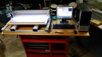
"The Moagie Mill" My C-Beam XLarge
Build in 'CNC ROUTER BUILDS' published by Glenn Weston, Feb 18, 2018.
My Experiences building the C-Beam X Large. Maybe you can pick up a few pointers from my ramblings and experiences if you are considering building this machine.
-
-
Build Author Glenn Weston, Find all builds by Glenn Weston
-
- Loading...
-
Build Details
- Build License:
-
- CC - Creative Commons Public Domain (CCO 1+)
Reason for this Build
To be able to route parts for my Flight Simulation project, like control panels.Inspired by
C-Beam Machine

