This build took me around 3 months of on and off tinkering. This being my first CNC, I didn't really know what I was doing. It's put together from mostly scrap parts with a few nice things, like the Nema 23 steppers that I wanted for this particular build.
This was a budget build, and I have approximately $450 in this, including 3 arduino's, 3 CNC hats, (the first two lived a short, and explosive life) 3 84 oz/in Nema 17's that are now part of a 3d printer DIY build, 9 DRV8825's, and 4 extremist A4988's that drank the coolaid. All said and done, it works, and I'm glad I did it this way, although it was certainly more expensive than it should have been. I had to rebuy and rebuild parts, try new things, experiment to see what worked and what didn't. It was well worth the effort and frustration. This has forced me to learn new skills and perfect ones that I already had. I'm glad for the opportunity.
Torsion Box Table
The build table is a torsion box made from 3.5 inch strips of 3/4 inch cabinet grade maple v-core plywood. This was just scrap I had left over from other jobs. The top plate of the torsion box is the same 3/4" maple ply. The bottom is 6mm maple faced mdf core ply.
Wasteboard
The wasteboard I cut from 18mm mdf, and projects slightly past the 49 inch by 25.5 inch build area. The surface itself is drilled through in 100 x100 squares with a 5/16" bit to allow access to the brass threaded 1/4-20 inserts that are threaded into the top of the torsion box. I thought this was the easiest way to produce reliable clamping without having to run the inserts into the mdf where they will not hold. This, luckily gives me access to a full 3/4" of wasteboard to level and clear before it needs to be replaced. No worries of mowing into 10mm tall threaded inserts by accident. This was happenstance rather than smarts. Seriously.
X Axis
Axis Support
The build area is bracketed on either side along the x axis by 4" x 4" plywood tubes made from 3/4" maple ply. I intended this to add a significant amount of rigidity across the long axis, and lift the supported rail along the x axis as close to the center of gravity of the router as I could.
Supported Rail
The rails themselves are fully supported, but built as cheaply as possible. They're simply galvanized 1/2" gas pipe fit into a routed trough. I bought this 7/8" core bit specifically for this task. I ran 2" wide strips of 18mm china birch ply through my router table, leaving a 1/2" deep 7/16" radius trough that was a perfect fit for the gas pipe. I then epoxied the pipe into the troughed runners, then pre-drilled for 1 1/4" #6 screws every 6 inches, spaced from center on either side of the pipe.
I'm mostly happy with this arrangement. It was very sturdy, and offered a fully supported rail system that was inexpensive and accessible.
X Axis Plates
The plates are made from laminated 12mm baltic birch plywood. 2 layers, glued and clamped together for a total width of 24mm+/- . This arrangement is substantially stronger than even ungoldly thick mdf.
The MoE of mdf is 4, MoE of baltic birch laminations is approx. 16, the MoE of aluminum is around 60. 24mm of baltic birch is roughly equally as strong as 6mm aluminum, and 4 times stiffer than mdf. This is why I chose not to use mdf for other than a wasteboard.
X Axis Trucks
The trucks themselves are just angle aluminum with skate bearings on posts. Simplest arrangement, and cheap. I did include an adjustment mechanism for these that press the bearings against the gas pipe evenly, but I don't recommend this for a permanent solution. I enjoyed the build, and would encourage others to follow suit, but know that I do have my own build planned using 20x80 and v wheels, just like everyone else. It's lighter, it's cheaper, and it's much easier to set up.
Y Axis
The y axis gantry is actually slightly wider than 1m. It's basically a torsion box made of 12mm baltic birch, glued with type III titebond and screwed judiciously, hence the look, and the name, "Domino."
The supported rails are, again, gas pipe let into a piece of troughed plywood and screwed to the torsion box gantry. I did have to very slightly shim beneath one rail to even out run. This is a reliable way to compensate for production errors, and I can recommend using this arrangement with the gas pipe and gantry.
The trucks of the Y axis box plates mirror the x axis arrangement, complete with top accessible adjustment screws to tighten or loosen the gantry run.
Z Axis
The Z axis is interesting in that I used some odds and ends to cobble something together that works fairly well, and is fairly stiff, particularly for a build like this, I think.
The rails for the z axis are 3/8" drill rod (cut from extra long drill bits from harbor freight and cleaned) let into 12mm plywood at their ends. The bushings that run on the drill rod are merely chunks of HDPE remelted into solid blocks from a paint bucket (2 actually).
It was particularly challenging getting the z axis to run well, and it still has a bit more friction than I'd like but it's amazingly sturdy for some drill rod and a paint bucket. What? I even impress myself sometimes. Usually with my stupidity, but this time, I was pleasantly surprised. It works. Like, wow.
Transmission
I experimented quite a bit and tried several different things before settling on the arrangement I have now.
I tried ACME 1/2-10 single starts and I was not happy with that at all. It was slow, added unnecessary friction, and had a horrible amount of slop that was finicky and difficult to reduce. It was, however, cheap-ish coming in at just below $50 for both the x and y axis with just a bit of welding. In my opinion lead screws on long axes aren't worth it. Ball screws, at the very least have precision that lead screws don't and can be had with a full assortment supports, bearings, and well-made couplers for merely 3x the investment of the cheapest lead screws. Multiple start lead screws are comparable in price, or actually more expensive than ball screws.
IMHO, not worth it.
I ended up with 9mm GT2 belts on the double x and y axes. This works reliably, is fast, and translates to smooth movement with low friction. It's also amazingly easy to set up as the motor mounts and idler plates can be combined into single pieces than can be cut, arranged, and placed quickly, particularly on a plywood machine. Ease of assembly and maintenance counts. It really counts. A lot.
The Z axis is a 250mm t8 trapezoidal lead screw. These are amazingly cheap, reliable, move at a reasonable rate, and with a AB nut, produce good enough results. I have mine pinned in place with the coupler and a stop collar, the lead itself running on skate bearings let into 12mm plywood. I'm very happy with this for now.
Electronics
I had the hardest time with this, as it was mostly new to me beyond some light soldering. The setup I'm using now:
4 low current Nema 23, 306oz/inch (these are a real gem, found them on Amazon, rated at 1.05 amp)
4 DRV8825 drivers (currently have these set with a ref voltage of 0.5)
Arduino Uno, Grbl 0.9j
CNC shield v.3
MeanWell 350W 24V power supply
2 12V fans
12v 500mA power supply
Rocker switch
The CNC shield will not support high current motors! I popped 2 of them and burned a fuse on a 3rd (manually replaced, works now).
This setup is testy, unreliable, but works. I don't recommend it, but for testing, prototyping, and experiments, it can't be beat. It's CHEAP.
The X and Y axes are set to 1/16 step. The Z to 1/8.
I am absolutely open to suggestions for a more reliable electronics package.
Post-Build Thoughts
I wasted a lot of money on attempts and experiments. If I'd known then what I know know, I would have used 80x20, v wheels, and ball screws. At the very least, I'd have used GT3 belts, which I've read great things about, but I had already blown my budget on pointless 1/2-10 ACME.
What I have now works, and works pretty well for what it is, though I consider it a strong baseline for further improvement rather than a finished product. I want ball screws for it. Some extrusions. I'd like to start with upgrades to the Z axis and work outwards from there.
Plans
I am pretty sure I'm going to produce a set of plans for this particular build if it proves to be reliable over the next few months. As a way into building a CNC, I'm fairly impressed, but it's pretty easy to impress me. It works, lol.
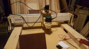
The Domino - 1.5m x 1m
Build in 'Cartesian Style CNC' published by Jones, Oct 27, 2018.
DIY scratch build consisting of gas pipe, skate bearings, 12mm birch, 3/4 maple v-core ply, Nema 23's, and arduino and CNC shield with DRV8825's.
-
-
Build Author Jones, Find all builds by Jones
-
- Loading...
-
Build Details
- Build License:
-
- CC - Attribution - CC BY
Inspired by
Random scratch builds on youtube, the OX from OpenBuilds -
Attached Files:
-
![20181021_210521[1].jpg](data/attachments/35/35375-cf5b43fc5c376061ef026196dbf2948f.jpg)
![20181021_210524[1].jpg](data/attachments/35/35376-475e2d466e28f2994b25a09b8c83f4c3.jpg)
![20181021_210529[1].jpg](data/attachments/35/35378-e1a3ae6553451c2ed7d1bfd8c8353d5a.jpg)
![20181021_210514[1].jpg](data/attachments/35/35379-5524360c92d324c8321e1868b4b23ec9.jpg)
![20181027_153357[1].jpg](data/attachments/35/35445-6ef6e75e9f22d549f0491727212a8714.jpg)
![20181027_153359[1].jpg](data/attachments/35/35446-d33e1ec394147e1e960c1617261a8c8d.jpg)
![20181027_153402[1].jpg](data/attachments/35/35447-1b4dcf3daf5ec7c3e2fa015a94cc0f1c.jpg)
![20181027_153408[1].jpg](data/attachments/35/35448-4b309bdfe8f991d1d0fabb42e7bb40de.jpg)
![20181027_153415[1].jpg](data/attachments/35/35449-31dce9ba2e1d6890ca542cfe5d8d419b.jpg)