
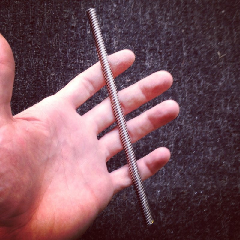
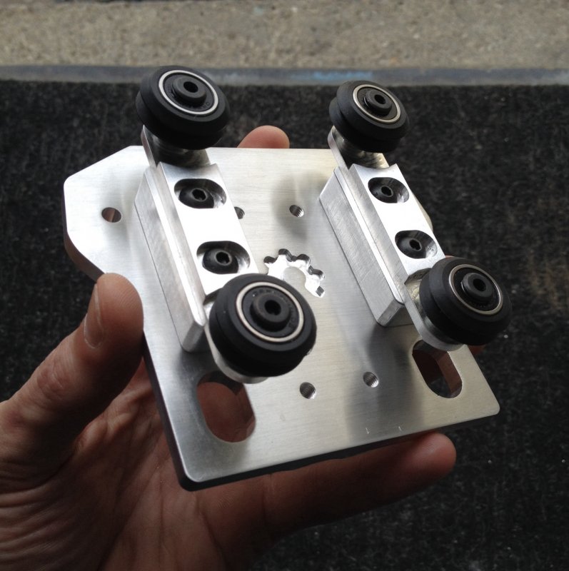
I first started off by going through my sketch book and decided I wanted to incorporate an idea I call the Tension 20 into my design.
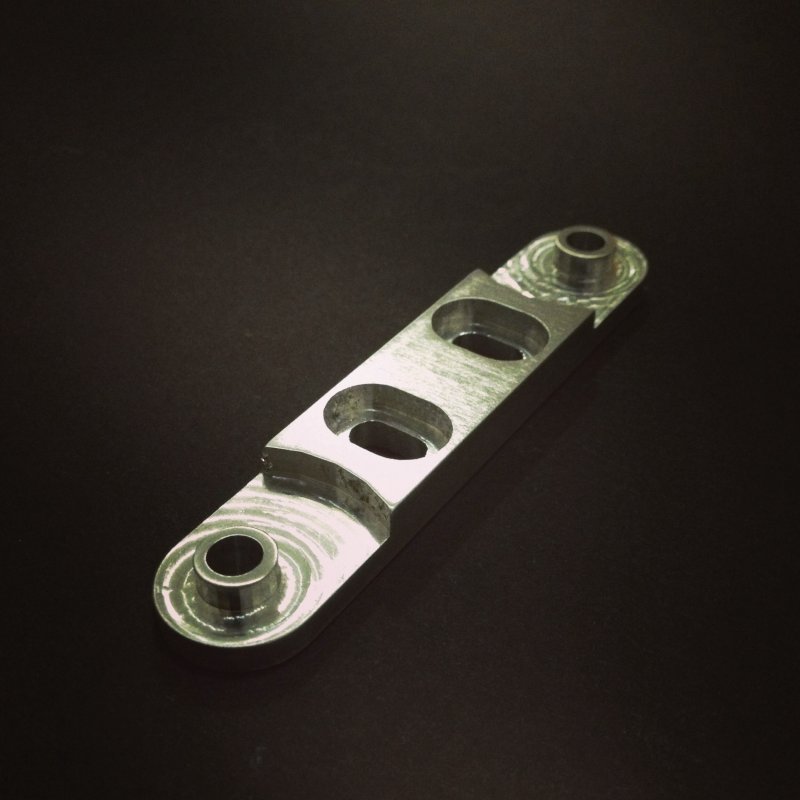
It can be used in many ways and I use them in all axis of the build.
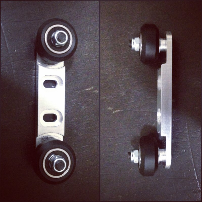
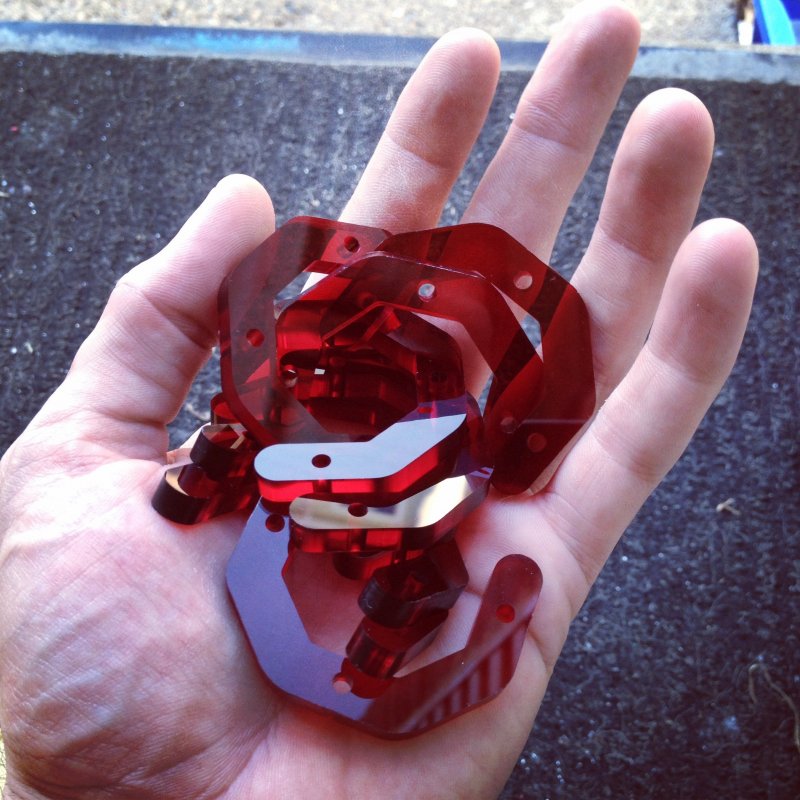
Here you can see how they go together
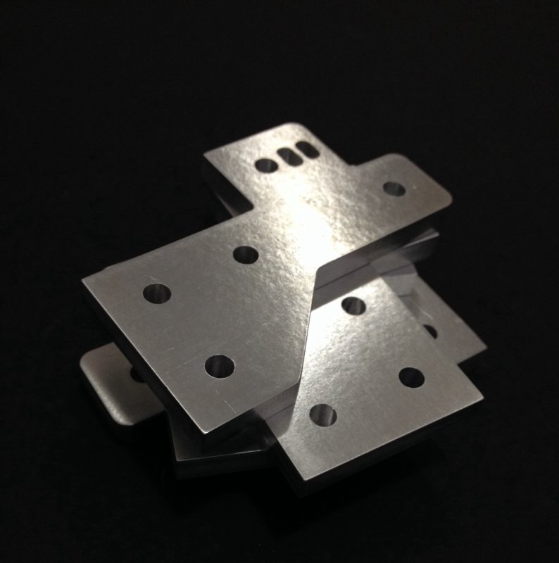
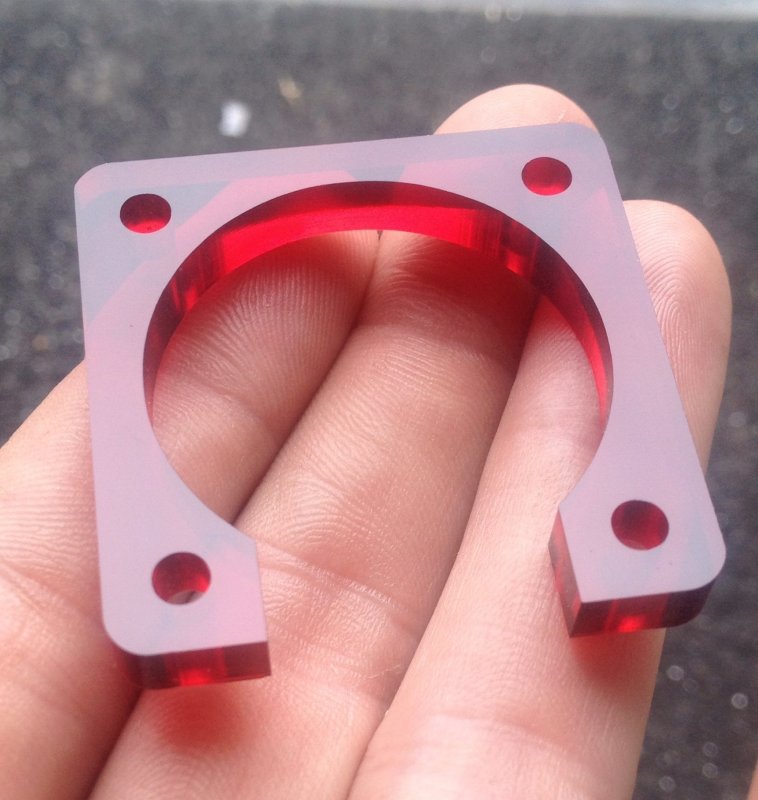
Next came the side plates, I wanted something compact but strong.
I of course incorporated my belt clip design into them, then milled a par from 1/4" 6061 aluminum plate.
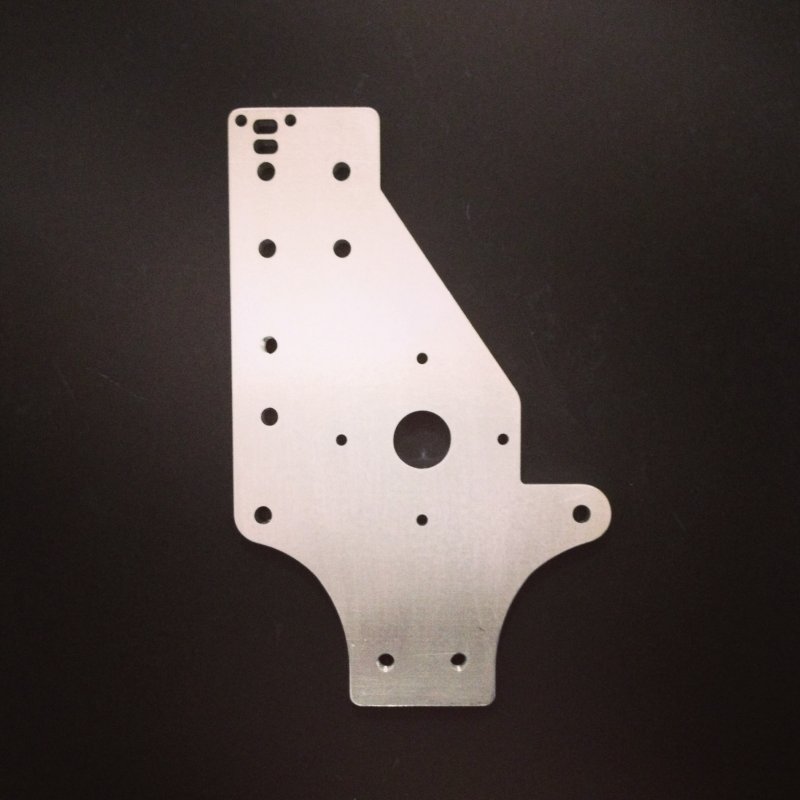
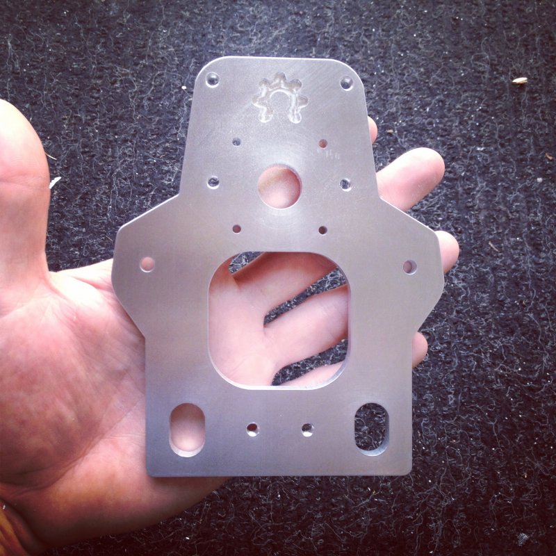
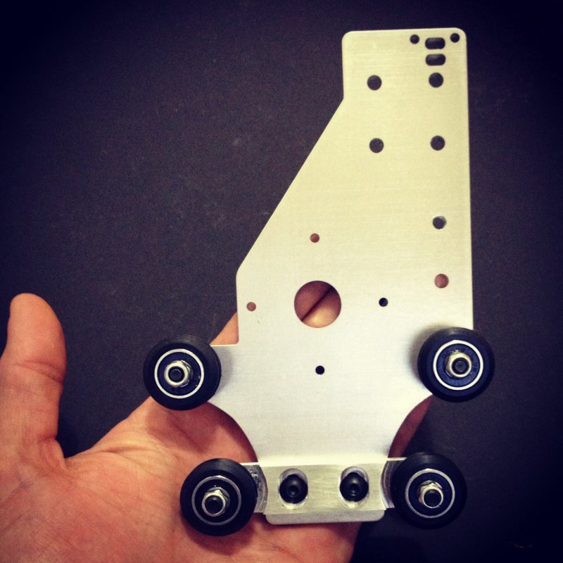
For the X axis I designed my carriage around the OX's design but a little smaller yet just as robust.
Front plate with m5 tapped holes for the leadscrew nut and lower Tension 20
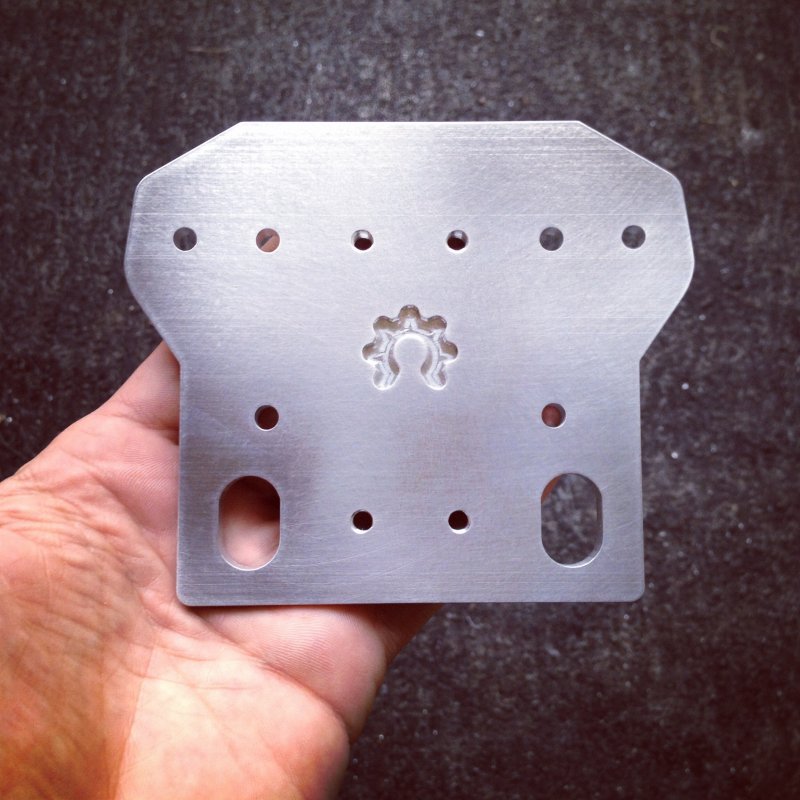
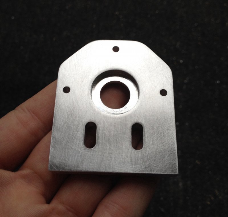
Back/motor plate
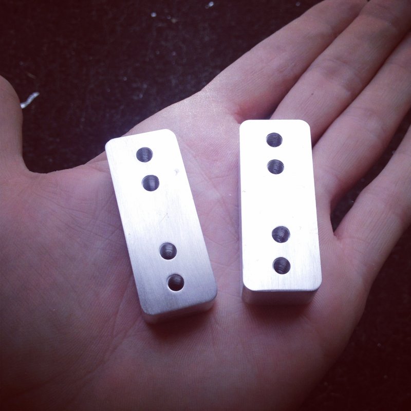
I then milled a set of small spacer blocks for the Z assembly.
Next I designed and milled end plates using another idea I had floating around in my nerd.
Then a set of Z plates as I used in my OX AI build sized for 20x40
The bottom plate is identical simply no motor mounting holes.
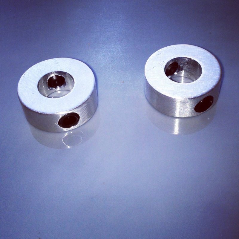
Back to the mill I went for some 8mm lock collars to lock the Z axis leadscrew from the openbuilds store in place.
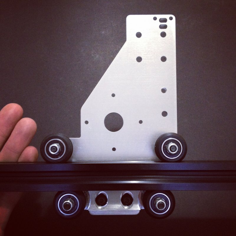
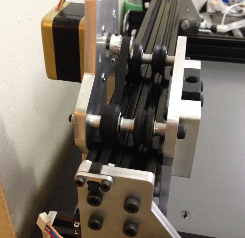
Here I lightly attach a Tension 20 to a side plate that has had the upper wheels mounted using 30mm M5 hardware in place of what comes in your wheel kit.
I use 2 x 10mm screws for the Tension 20
Then I pinch and tighten the Tension 20 onto a scrap 20x20 v slot to adjust things just right
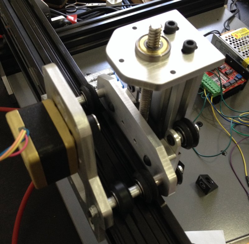
I did the same for the other side and mounted my motors
As with my OX AI, spacers where needed for the Z and motors all around.
8 three hole spacers and 1 four hole for the X axis
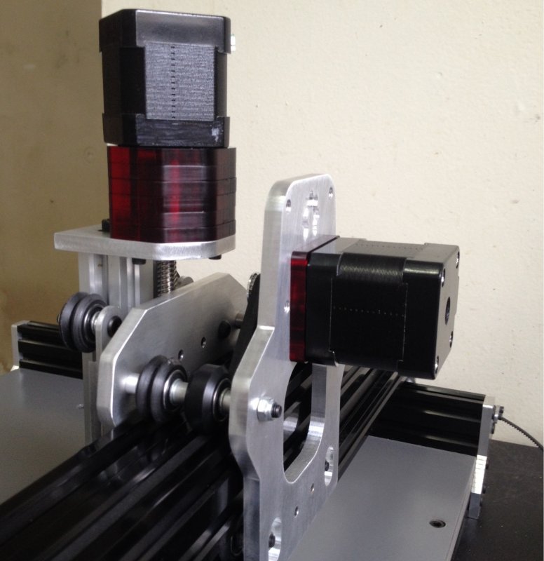
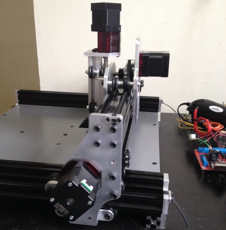
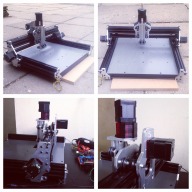
So here are some pics of it together and I'm going to keep it short as I plan to make an assembly video on how it all goes together
The motors you see where for testing and mach up
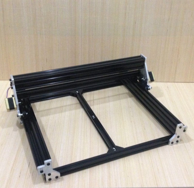
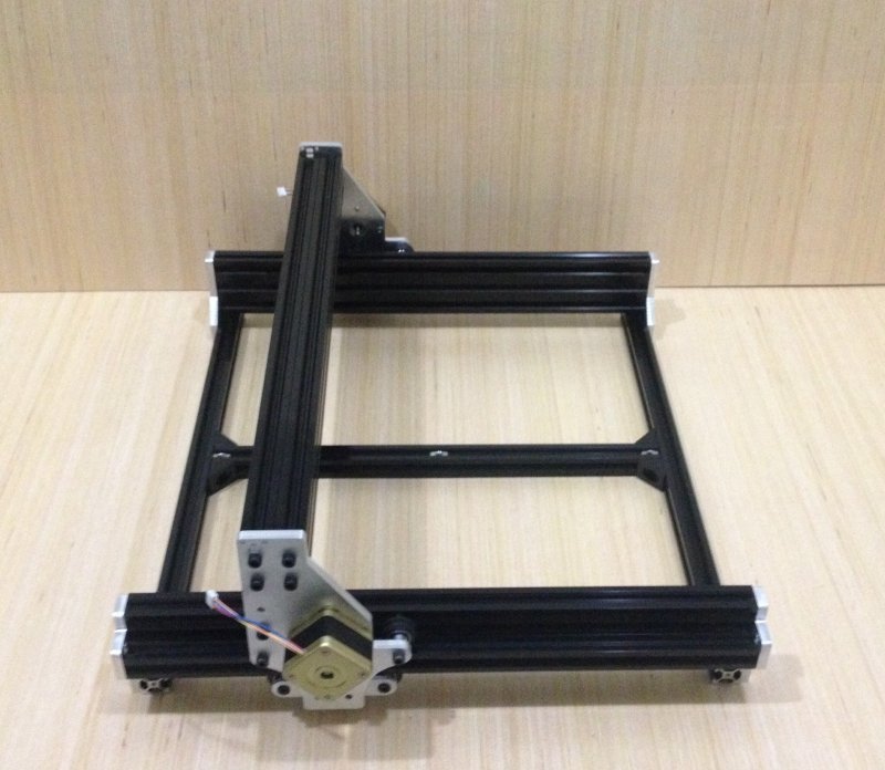
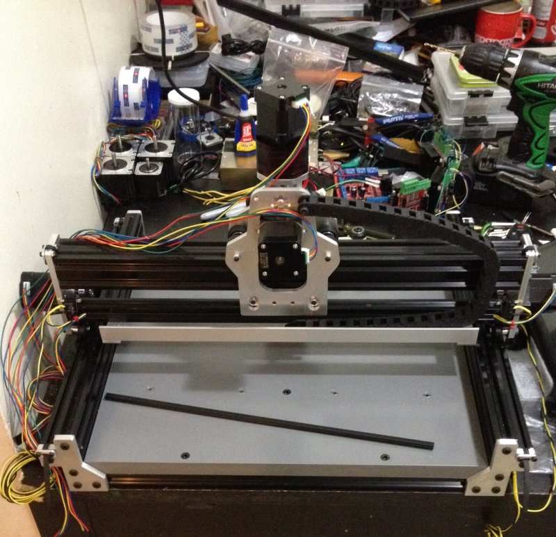
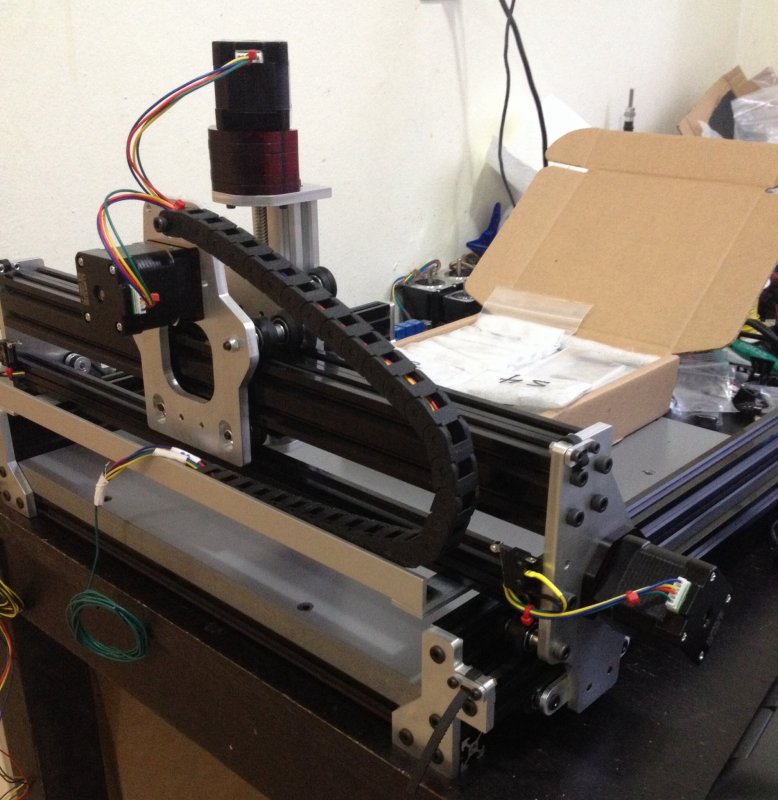
Here you see me testing the X / Y axis
My motor order came in along with a few other iteams I needed from the store and I picked up a 3/4" sheet of MDF cut to size for the spoil board.

It has screw grubs for PCB tie down and the finish is a gloss gray rustoliom paint.
I'm now finishing up wiring and then on to the controls
So for the controls I have decided to go with a board a lot like the LD2X I designed for the Laser V
Keeping things simple the board will allow me to run 4 step-sticks along with an Arduino Nano in a simple plug and play format with all pins broken out for output and input communication.
Here you see me laying it out.
The Y axis has two drivers, one for each motor and again I'm keeping it single sided for easy DIY
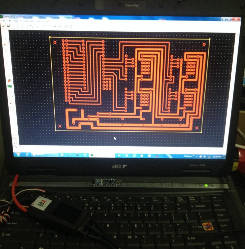
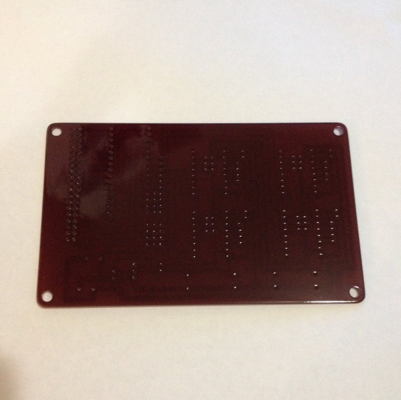
Here you see the test print and the positive image for my exposure unit.
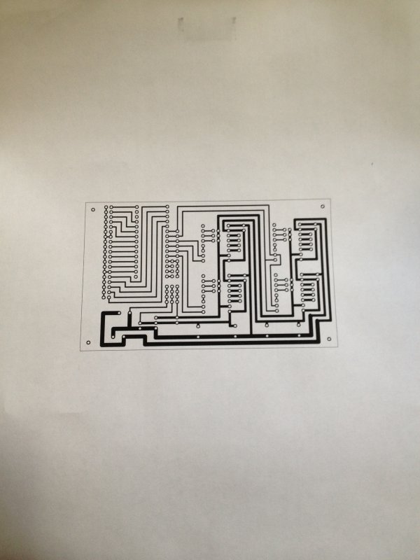
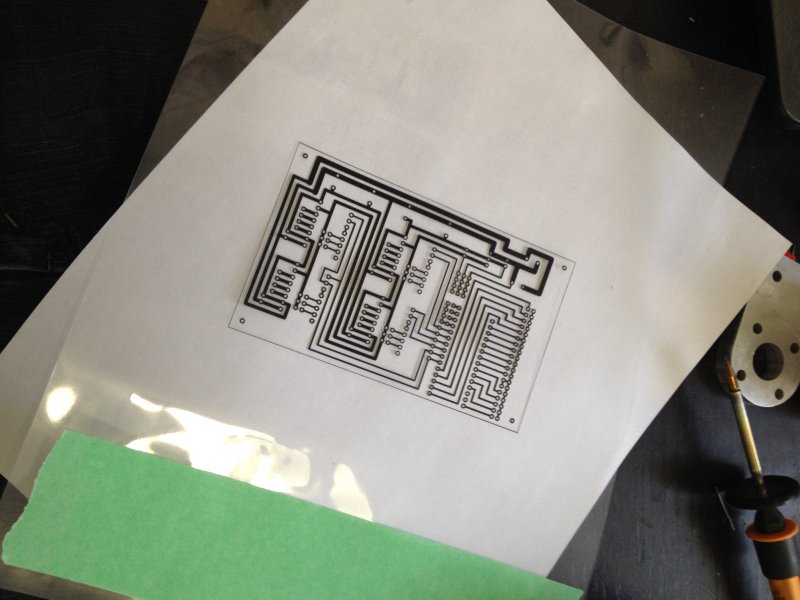
I then mill out some PCB and expose it on my UV setup
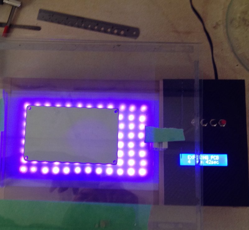
The board is then developed in solution cleaned/dried and inspected before drilling all the holes
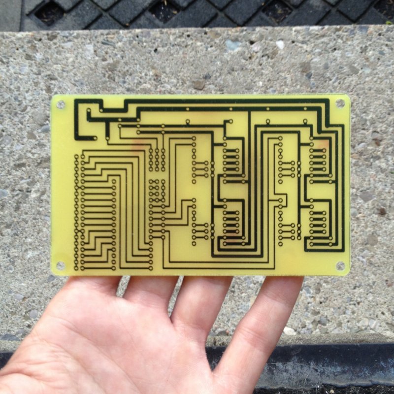
Here you see the finished board with holes and then with all the parts installed and ready for testing.
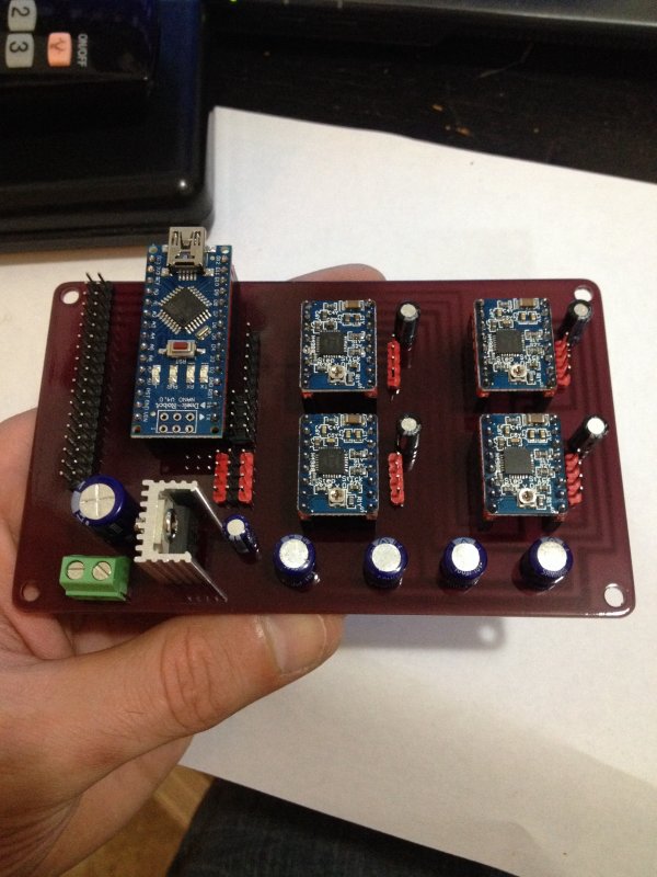
Here I have modified the pin out in my grbl hex and tested each driver
I decided to build the relay control in the form of a module so I could add as many as I wanted for controlling spindle, vac and so on
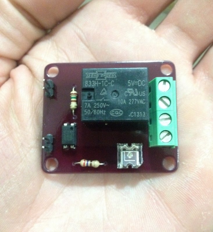
I then wired them to the shield and tested them out using a little hand written code
So I planed on using a 12vdc power supply but lucked out and had 4 small rack mount power supply's given to me.
I took one apart and converted it into a power supply that will supply the stinger with more then enough juice
A 5 watt 10 Ohm power resistor is hooked up to the 5v rail to draw load in turn bringing the output voltage to 12.67 vdc
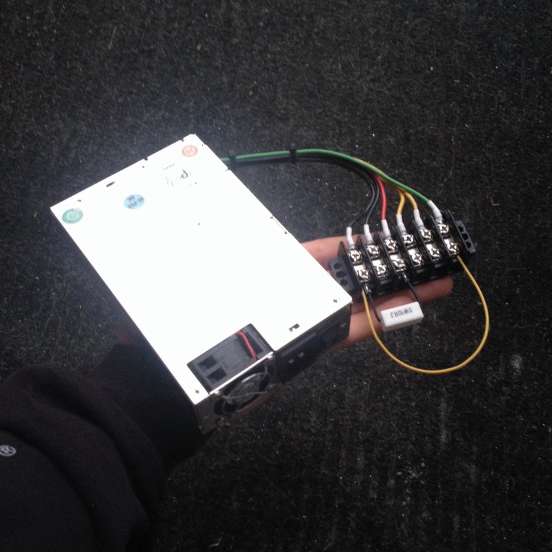
To give the power supply a test along with getting a chance to see how the stinger moves with the new motors, I wired it up to my board and plugged in both X / Z axis motors.
Here is a clip of how that went
Stinger V Micro Mill
Build in 'Cartesian Style CNC' published by Robert Hummel, May 24, 2014.
While building my OX AI I found myself with left over v slot and thought to myself, what do I need that I can build using them? Well since I make a lot of my own PCB boards for projects I figured a micro PCB mill would fit the bill ;) With inspiration from the OX and OX AI I give you the Stinger V :)
-
-
Build Author Robert Hummel, Find all builds by Robert Hummel
-
- Loading...
-
Build Details
- Build License:
-
- CC - Attribution - CC BY
