
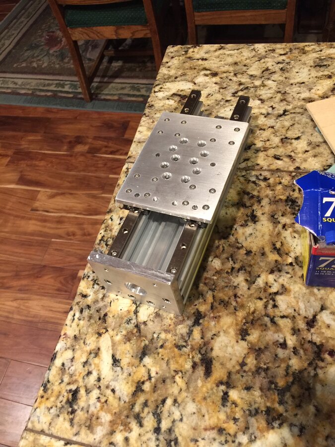
Rebuilding the Z axis I bought some MGN12H rails 250mm There the black ones not the red and green. found them on Amazon and they came with spare bearings, about 5 extra bearing. Al most didn't see them had to go thru thru the trash once i noticed them.I adjusted the the Bearing placement too account for a 1/2 thick spacer to attach to my Z plate to the lead screw nut block. I also made the z plate to hold 2 Openbuilds clamps too hold the spindle more ridged. I still have to 3d print another insert for the 65mm Makita 701c. I have not used the Makita but once I felt like it was to heavy for the current setup. Depending how how sturdy 2 clamps are. I have also drawn up a side plate to attach to the 2 holes on the side of the clamps. So I swapped back to 500w spindle just to get these plates made. I have the rails and the motor mount and Z plate mounted to a mock c beam.Thoughts on the 500w spindle, it works good obviously you have to find a sweet spot. So far I used the 3 flute 6mm, 4mm, and 2mm end mill. The 2mm EM seems to be have good chew factor i guess to say at about half the throttle of the pot maybe 6000rpm and Cutting Feed @ 200mm/min as its taking a.10mm cut, it chews thru aluminum really well not chatter no jumping around. I have only bored all holes on the plates cause its faster and more reliable I have found then trying to adaptive clear. And pocketing takes to long at that speed. The 4 and 6mm endmills I have used them but I have not found sweet spot yet. I get chatter here and there and need to tweak the speed and feed. Fastest I have ran the 6mm is at 300mm/min taking .10mm cut. Well until I get new Z axis built I am not going to comment on the speeds for bigger end mills no point till i find a good solution
.
06/24/20
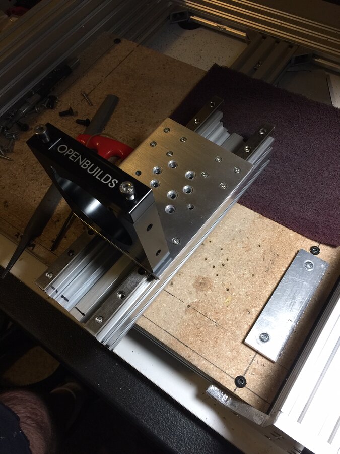
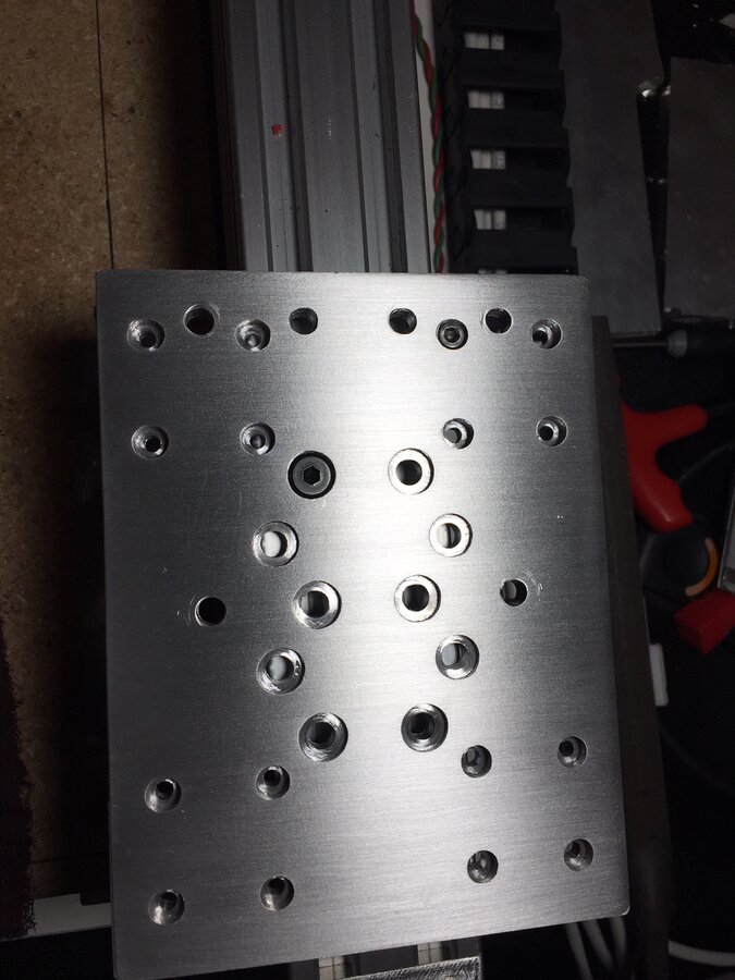
Finished the motor plate had to finish the cutout by hand trying to work out speed and feed with a 1/4" square end mill for cut out. Not getting very far going to take suggestion from Peter Van Der Walt and get a ZRN bit. Here's a pic of the last motor mount of Y axis and you can see a couple of crashes along the edges. Well pockets and holes were cut out without a hitch. So at least I can get this machine to place the holes and cut part out by hand. As soon as i get the Z plate cut out i think it might be smooth sailing for the right And left plates to the gantry.
7/5/20
6/11/20 Update
So I wanted to replace the 3d printed end plates to Aluminum. I had a copy of the DXF files for the Sphinx plates when KYO posted his finished project. That how I 3d printed them. I am not claiming design I give all credit to KYO but I modified plates to 3/8" thick plate with pockets for allen bolts. And to except the bearings I had lying around and bought for another project I never started. Possibly might make a small bearing catch or a drop of Locktite to hold it in. It is a tad snug but the right amount of jiggle and they fall out! I did have to finish them by hand, the last 2mm of part cut out. Router had collision and had to stop the job. Blew fuse on the powersupply to spindle but I got the pockets and holes done. These are the bearings I am going to use I'm not saying there the best Just what I had and I wanted make them work. I also uploaded the Fusion360 file for it.
https://www.amazon.com/gp/product/B01GLQXYZ4/ref=ppx_yo_dt_b_asin_title_o03_s00?ie=UTF8&psc=1
This has been awesome time building. I wanted to say thanks to the amount of information I have gotten from Openbuilds community forum. Information is key. I just wanted to share a alittle of what I built.
I did 3d print some parts, Although I read multi posts that its not worth it to print parts for a router that there is some flex when in use. So I beefed up the printed parts to 100% infill and 10mm thick. I use the Sphinx DFX files and modified them in Fusion 360. I used the another Design in the spindle mount cause I thought it would hold the spindle more rigid. It does there is alittle flex that I need to add a support to the top of spindle motor. But in all it works good. I wanted to try to keep this on the low side of the budget. But we all now how this goes. The end plates on the Y and Z axis are 3d printed and the side plates on the X axis are 1/4in aluminum cut out with a non ferrous metal blade on my table saw and holes drilled on my not so great Harbor Freight drill press. I 3d printed the standoffs holding the stepper motors and the Limit switches. I am using Openbuilds lead screw and lead block for movement.
On to the controller so I wanted to use a Arduino platform. I ended up going with a mega 2560 and a shield from the Eccentric Workshop. Also used there Opto couplers for the mechanical limit switches. I did have questions on wiring and the help there was awesome on there forum. I also wanted to make sure I didn't get any noise from the stepper motor wiring so I got 4 conductor shielded wiring and landed all shields thru a bus bar tied to earth thru my ac outlet. I used the same wiring for my limit switches. I used power 2x24v 15a psu for the stepper motors. 2 motors for one PSU. For the spindle a Chinese 500w from amazon. Any non shielded conductors I stuck the wire in the end my drill and twisted it to help with outside interference. Any wire that I could not twist cause of a sheath I shorted out one end and ground other end to the chassis earth ground. Hopefully to create a drain for unused wiring creating a antennae effect for EMI's. I don't think I need build pics cause its a well known build so I thought I would stick to the important stuff. The picks of panel I designed and router out are a couple of pieces for my simulator. I'm still working out my layout for the panels and learning the machines capabilities. SO as for the info that I have used to build this I believe in free help and info anything I have written about or drawn is available for free. I have no idea what to use on the build license or what it is for so I put the what seemed like the most open! Thanks! Corey
![[IMG]](proxy.php?image=https%3A%2F%2Fibb.co%2FM7RQR72&hash=5f132538602f5e80f8ad607c2187c7c7)
Sphinx Derived Router
Build in 'Cartesian Style CNC' published by Corey Corbin, Jul 6, 2020.
I Like the Sphinx design thought I would attempt my first build. I wanted to build this and use Arduino controller with GRBL to be able to learn and understand my machine.
-
-
Build Author Corey Corbin, Find all builds by Corey Corbin
-
- Loading...
-
Build Details
- Build License:
-
- GNU (GPL3+) General Public Licence
Reason for this Build
I was intrigue with having a home cnc. I also needed one to help build a flight sim cockpit!Inspired by
The Sphinx CNC -
Parts list
-
Attached Files:
-
![[IMG]](proxy.php?image=https%3A%2F%2Fi.ibb.co%2FnLxsWT5%2FIMG-1632.jpg&hash=8261367c0ebebcd056c3251312a3c7cc)


