
Hi All! A long time ago, I used to build CNC machines for a large Carbide manufacturer. It was fun and when I look back, probably the most fun I've had in my adult life. It has been over 25 years since I built a machine and much has changed. It is really for the better. There are however some basic rules that should be followed and I have noticed that often they are either missed or possibly ignored. I am going to attempt to follow as many of these basic rules as possible within my cost limits. I am trying to build this machine for around $2,000. I am willing to go over if needed but with what is available out there now, it should be achievable. My target is 1 meter x 1 meter work surface.

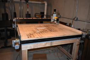
I started with a wood table, it was much cheaper than metal and the way I built it, it should be pretty strong. I notched both the top and bottom pieces carefully marking each intersection, and then fit the grid into the top frame of the bench. I then screwed all the pieces to the bench frame top using some hefty Kregg HD screws. I clamped each intersecting joint to force the joint level and then drove a wood finishing screw through the joint.

Then I put a quality plywood top on the frame (furniture grade) and bored lots of holes into the grid below in a pattern that avoided the intersection points. Each hole was countersunk. I used stainless steel screws, filled the holes with wood filler and sanded the whole surface flat with a sanding block. I then used a grey lacquer finish to finish it off. Kind of a shame considering when the build is complete, you won't see the top!

I decided to use V-Slot rail. I have been very pleased with what I see. Now, here is something that I feel is fundamentally important when building a base/frame for a CNC machine. The more support across the length of the axis, the more accurate the machine. I have seen many OX designs and I'm sure they work fine when then length is minimal, but the rails are usually suspended by each end, with no support along its length. To further make things worse is I have seen builds that then put cross supports parallel to the rails. This provides no rigidity for cross loads such as moving what I call the Y axis back and forth rapidly.
What I have done is simple but makes a BIG difference as far as reducing deflection and providing rigidity. I put 3 cross support perpendicular to the rails. I have then hung the rails out over the edge of the top. By doing this, my rails are supported Every 12 inches or so. I also have a great deal of rigidity because my cross supports are perpendicular to the rails. Bottom line is, the shorter the distance the rails go unsupported, the less deflection in the rails.


I couldn't find gantry plates that would really work for me so I decided to make my own. I used two 8" x 11" pieces of heat treated 6061 aluminium I ordered from Online Metals. I used my drill press and carefully laid out my drill pattern. A fence is an absolute must to do this but you can do it yourself. Just remember that the distance between the doles needs to be 20mm more that the actual rail width. For example, if you are using 80mm rail, and it measures out to 80.5mm, just add to to that to get your distance between holes of 100.5mm. Also, remember that either the top or bottom holes must be drilled for eccentrics. I can save you some time on drill sizes.... There isn't much info out there but the eccentric holes (7.12mm) are drilled with a 9/32 drill bit, and the 5mm holes are drilled with a 13/64 drill bit. The plates came out perfect and the V-Slot wheels all engaged properly. I also thought that I could have optionally drilled the inner top holes for eccentrics and then adjusted the gantry plate with the top middle wheels disengaged after the bottom 4 wheels are engaged, you could adjust the 2 middle wheels. Turned out the plates were drilled accurate enough that this was not needed. It is an option though.
![IMG_0568[1].JPG](data/attachments/23/23805-13a9091335ddf88e9d6376b20eae10aa.jpg)
To control this CNC I decided to use a Raspberry Pi 3 board and a Protoneer CNC hat. As you can see, there is a very small foot print to this combo but let me assure you, plenty of power to do the job. One of the nice aspects to the RPi3 is is has built in wireless. I just connect to it via Windows remote desktop. So far, I have had no issues testing the stepper motors.

I mounted one of the gantry plates and began testing the setup. I have the stepper set to 20,000mm per minute. Plenty fast enough (covers entire length of CNC in 3 seconds), lots of torque. The steppers I'm using are 340 oz. in. motors. I have 2 for the X axis. Another comment I've seen on different blogs is about inductance in a motor and if it is high, it must be a cheap Chinese motor. There are many reasons why inductance would be higher. I good reason would be if your motor has large windings.... Like, say a 340 oz in. motor! As the motor goes faster there will be more generator action as it will limit current flow which will lower torque. Just keep in mind that motor inductance will affect ftorque to drop off at higher RPM's. With the GT3 belt drive, the Axis moves 2.36 inches per rev. This works out well for the longer bodied stepper running at slower speeds. I love these motors because max amperage is 1.8 amps and that matches nicely with my CNC board.
![IMG_0609[1].JPG](data/attachments/23/23879-8c9134c76d5f525e01d519a1c4a34aeb.jpg)
I received the 1/4" 6061 aluminum plate yesterday to fabricate the Y and Z axis. Finished drilling them today. I decided to put double wheels on the four corners between the plates but the motor plate has two single wheels in the middle mostly to guide the drive belt. I think it will work fine, but we'll find out when it is up and running how well it works. Now I need to wait for a bunch of parts I've ordered.
![IMG_0613[1].JPG](data/attachments/24/24024-ad1baffcd95ef3fc86a817b6c7ef6e3f.jpg)
20 V-slot wheels showed up today and I was able to put the other gantry plate on, build the Y axis and install the other X axis motor and the Y axis motor. Everything is square so far. The gantry is extremely rigid side to side thanks to the cross pieces.I will find out how well it holds position pretty soon. I need to order a couple of t nuts to anchor the belts.... And also unbolt one side of the Y axis to put a couple of them in, darn.
![IMG_0623[1].JPG](data/attachments/24/24114-4ef799c80890b63a423278d0cde1f530.jpg)
FInally, I got the t nuts and set screw today and had a chance to test the X and Y axis and I'm quite pleased so far. Now I need to finish up the z axis. Here are the results of a quick circle test and a video.
![IMG_0646[1].JPG](data/attachments/24/24675-eda43c42e35e8e34800589a0f817ed6d.jpg)
Working on Z axis now. I had to modify the end block for the c-beam extrusion to use it in my application but it came out OK. Now I need my new power supply to show up so I can do some X-Y-Z testing and then make something!
![IMG_0687[1].JPG](data/attachments/25/25082-cd842b3164df494aa3b0ff4280922a1f.jpg)
Z axiz is now hooked up and doing great! I have run the CNC through g-code to drill a cribbage board and it has returned perfectly to the home position after about 20 runs @ 11 minutes each. Today I added the Dewalt 611 router. Well built tool. I will actually run a Cribbage board in the next few days and see how it does.

Sorry for the long absence. I ended up having lots of problems holding tolerances while routing with the belts. I tried everything but ended up doing what I probably should have in the beginning: used ball screws. I made the big change in September and it has been great! Making lots of things now that are to spec. Most notably is circles. I had lots of problems making true, round circles such as the centers of coasters where you put the cork. I won't call it completed yet since I still need to set up the vacuum system and probing system but I do pretty much what I want to do.

I made a few squares on the machine and drilled holes every 5" so I can mount them all over the place.
Here are a few pics of the machine axis. I reused the plates for the ballscrews. They don't seem to mind at all!


And here are a few items I've made on the machine:


Solid basics CNC router
Build in 'Other Style CNC Mills' published by Richard Long, May 7, 2018.
This build focuses on the basics to provide a good foundation to further enhance the ability to achieve tight tolerances
-
-
Build Author Richard Long, Find all builds by Richard Long
-
- Loading...
-
Build Details
- Build License:
-
- GNU (GPL3+) General Public Licence
-