Step 0
Connecting Assemblies
This build makes reference to V-Slot® NEMA 17 Linear Actuator Bundle (Lead Screw) assemblies. These can be constructed separately prior to this build and be incorporated without need for disassembly when choosing option 2 or 3 from Step 7. By using the Drop-In Tee Nuts, the CNC Mill can be constructed. Use of other T-Nut types will require partial disassembly of the actuator bundles to insert T-Nuts.
Step 1


Base Frame
Cast Corner Brackets (in red) are used to fasten the base frame.
-Components-
Linear Rail 20x40 length 610mm Qty. 2
Linear Rail 20x20 length 500mm Qty. 2
Cast Corner Bracket Qty. 6
Step 2


Install Y-Axis
A V-Slot® NEMA 17 Linear Actuator Bundle (Lead Screw) 500mm is placed in the center of the frame with the forward end flush with the frame front. Cast Corner Brackets (in red) are used to secure the actuator to the frame.
-Components-
V-Slot® NEMA 17 Linear Actuator Bundle (Lead Screw) 500mm Qty. 1
Cast Corner Bracket Qty. 4
Step 3 (a,b)

Assemble Left Vertical Support
Attach Cast Corner Brackets to V-Slot® 20x40 Linear Rail 250mm. Upper bracket positions will be adjusted when completing Step 5.


Install Left Vertical Support
A V-Slot® 20x40 Linear Rail 250mm with Cast Corner Brackets is installed on the left side of the base frame. Two brackets secure the support to the frame while the others will be used to secure the X-Axis.

-Components-
Linear Rail 20x40 length 250mm Qty. 1
Cast Corner Bracket Qty. 5
Step 4 (a,b)

Assemble Right Vertical Support
Attach Cast Corner Brackets to V-Slot® 20x40 Linear Rail 250mm. Upper bracket positions will be adjusted when completing Step 5.


Install Right Vertical Support
A V-Slot® 20x40 Linear Rail 250mm with Cast Corner Brackets is installed on the right side of the base frame. Two brackets secure the support to the frame while the others will be used to secure the X-Axis.


-Components-
Linear Rail 20x40 length 250mm Qty. 1Step 5 (a,b,c)
Cast Corner Bracket Qty. 5


Install X-Axis
A V-Slot® NEMA 17 Linear Actuator Bundle (Lead Screw) 500mm is installed across the vertical supports using the Cast Corner Brackets (in red) to secure it to the supports.
-Components-
V-Slot® NEMA 17 Linear Actuator Bundle (Lead Screw) 500mm Qty. 1
Step 6 (a,b,c)


Install Z-Axis
Two spacers (in red) are placed upon the X-Axis gantry plate to provide separation when the Z-Axis is attached to the X-Axis gantry plate.
A V-Slot® NEMA 17 Linear Actuator Bundle (Lead Screw) 250mm is aligned with the X-Axis gantry plate center and spacers (in red) for attachment.
Upon attaching the Z-Axis, its vertical position on the gantry can be adjusted to fit your spindle selection's length.
-Components-
Aluminum Spacers 3mm Qty. 2
V-Slot® NEMA 17 Linear Actuator Bundle (Lead Screw) 250mm Qty. 1
Step 7 (a,b,c) (ax,bx,cx) (ay,by,cy)
Installing Spindle Mounting Rail
The Z-Axis gantry can have several different width V-Slot Linear Rail pieces attached to provide a mounting surface for the spindle mount.


The first option uses V-Slot 20x80 Linear Rail and four mounting points with spacers(in red). This mounting setup requires the spacer hardware and V-Slot to be installed onto the gantry BEFORE it is threaded onto the Z-Axis Lead Screw. This option allows for FOUR mounting points which spread the stresses of the spindle mount hanging off the gantry.


The second option uses V-Slot 20x60 Linear Rail and two mounting points with spacers (in red). This mounting setup does not require assembly before the Z-Axis gantry plate is threaded upon the Lead Screw. This allows the Z-Axis to be fully assembled before attaching the spindle mounting V-Slot 20x60 Linear Rail piece. This setup has only TWO mounting points for spreading stress of spindle mounting off the gantry.


The third option is the same as the second, however V-Slot 20x80 Linear Rail is used. This provides a larger area for the spindle attachment but does not center the mounting rail.
-Components-
Aluminum Spacers 3mm Qty. 4 (max)
Linear Rail 20x40 length 130mm Qty. 1
or
Linear Rail 20x30 length 130mm Qty. 1
Step 8 (a,b)


Attach limit switches (in red) to Axis.
-Components-
Micro Limit Switch Kit with Mounting Plate Qty. 3
Step 9

Electrical component connections are general described by this graphic.
Dashed lines represent MACH3 spindle controller upgrade intended for the future.
Step 10

Attach Spindle Holder (in red)
Attach Spindle Holder via four mounting holes. Two of the holes on the left side also secure the spindle in the holder via compression. The mounting holes are vertically spaced at 20mm.
-Components-
Spindle Holder/Mount (specific to spindle choice) Qty. 1
Step 11

Electronics mounted to rear side. This is customizable to match the electronics suite of your choice. Step 9 has a graphic of my setup and elements.
Step 12
An Arduino CNC Shield is used to drive the device. The Arduino UNO is running GRBL V0.9
The device is attached to a laptop running Universal G-Code Sender.
Some Photos


Sample PCBs Milled


The two images display an elegant and an utilitarian PCB milling. Interestingly they are both a variation on the same circuit. The first elegant PCB was designed using Fritzing. However the current requirements for the circuit (as well as some over current) caused it to delaminate the copper on some traces and fail. The second utilitarian version was able to handle the current requirements. These were used for an inductive heater build.
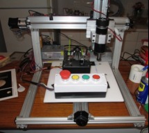
Small PCB, Engraving and Delrin CNC Mill
Build in 'X/Y Table Style CNC Mill' published by JAC_101, Feb 28, 2018.
This is my first attempt at building a spindle based CNC machine. The intention is to mill PCB boards and mill delrin blocks. The device was built with an Emergency Stop that actually cuts power to the spindle and motors. This is a post build write-up and consists of finished photo compilation and CAD renderings.
-
-
Build Author JAC_101, Find all builds by JAC_101
-
- Loading...
-
Build Details
- Build License:
-
- CC - Attribution - CC BY
Reason for this Build
I have previously built a 3D printer using an erector set type component system. The large variety of component choices actually was a distraction as multiple generic and special assemblies could be fastened together. I decided that a CNC mill would be my next project but I would discipline myself by using the OpenBuild component selection. This reduced overall component number for the Cartesian box and is more aesthetically pleasing.Inspired by
Built 3D Printer and 3D Scanner so CNC Mill was next step. -
Parts list
Qty Part Name Part Link Comments 2 V-Slot 20x40 Linear Rail - 610 mm length http://openbuildspartstore.com/v-slot-20x40-linear-rail/ Link Used generic 20x40 on actual build 2 V-Slot 20x40 Linear Rail - 300 mm length http://openbuildspartstore.com/v-slot-20x40-linear-rail/ Link Used generic 20x40 on actual build 3 V-Slot 20x20 Linear Rail - 500 mm length http://openbuildspartstore.com/v-slot-20x20-linear-rail/ Link Used generic 20x20 on actual build 2 V-Slot 20x20 Linear Rail - 100 mm length http://openbuildspartstore.com/v-slot-20x20-linear-rail/ Link Used generic 20x20 on actual build /non critical scrap used for drag chain support 1 Arduino Uno https://store.arduino.cc/usa/arduino-uno-rev3 Link Used generic on actual build 1 Arduino CNC shield w/ DRV8825 Stepper Drivers https://www.amazon.com/gp/product/B01JYYTUOO Link 1 CNC Spindle 500W Air Cooled 0.5kw Milling Motor https://www.amazon.com/gp/product/B01LNBOCDA/ Link CNC Spindle 500W Air Cooled 0.5kw Milling Motor and Spindle Speed Power Converter and 52mm Clamp and 13pcs ER11 Collet for DIY Engraving 1 Switching Power Supply 350W 24V 14.6A https://www.amazon.com/gp/product/B00XTHD00I Link 1 Red Green Yellow Emergency Stop Latching https://ww.amazon.com/gp/product/B01M12OC9Q Link Internal upgrade to Red button for dual N.C. switches 2 V-Slot NEMA 17 Linear Actuator Bundle (Lead Screw http://openbuildspartstore.com/v-slot-nema-17-linear-actu... Link 500 mm version (actual build from individual parts) w/ stepper 1 V-Slot NEMA 17 Linear Actuator Bundle (Lead Screw http://openbuildspartstore.com/v-slot-nema-17-linear-actu... Link 250 mm version (actual build from individual parts) w/ stepper 3 Jog Knob http://openbuildspartstore.com/jog-knob/ Link 3 Micro Limit Switch Kit with Mounting Plate http://openbuildspartstore.com/micro-limit-switch-kit-wit... Link Generic switches used on actual build 1 15 x 20mm 1.07M Drag Chain https://www.amazon.com/gp/product/B00843VYGO Link 22 Cast Corner Bracket http://openbuildspartstore.com/cast-corner-bracket/ Link 2 V-Slot 20x40 Linear Rail - 250 mm length http://openbuildspartstore.com/v-slot-20x40-linear-rail/ Link Used generic 20x40 on actual build 44 Drop In Tee Nuts http://openbuildspartstore.com/drop-in-tee-nuts/ Link