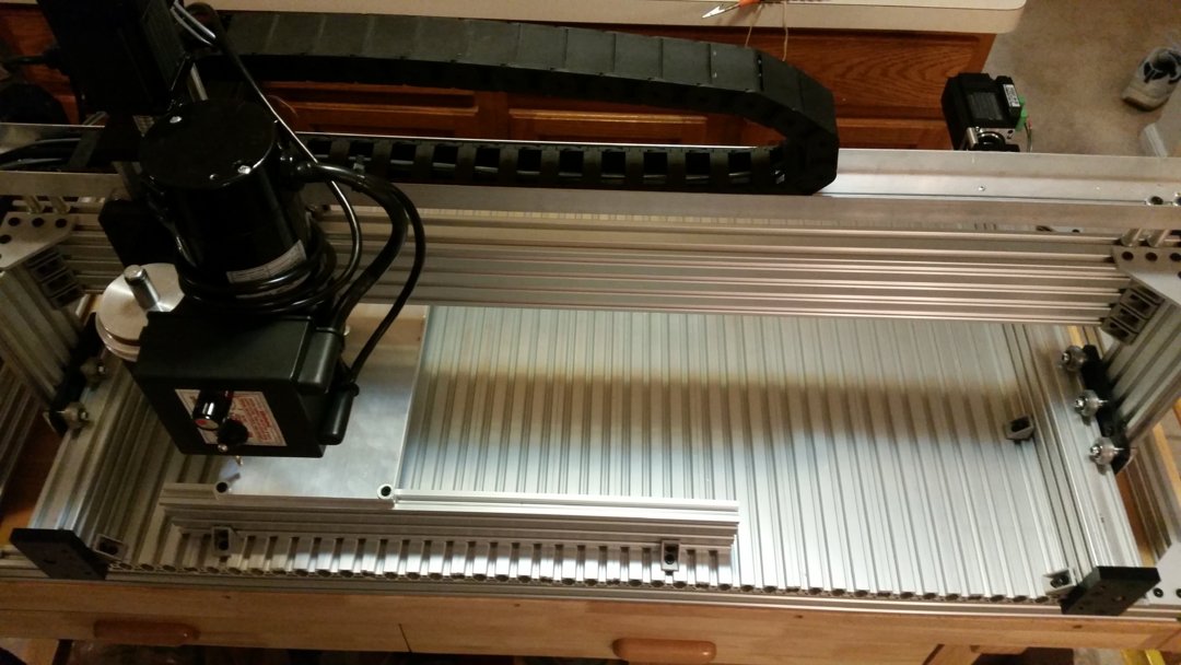
This machine is based on a 1000 mm C-Beam actuator for the X-axis, two 500 mm C-Beam actuators for the Y-axis and a 250 mm C-Beam actuator for the Z-axis. The Y-Axis actuators sit on top of two 20 x 40 x 1500 mm V-rails with a series of mostly 20 x 80 x 500 mm V-rails forming the cutting bed of the machine.
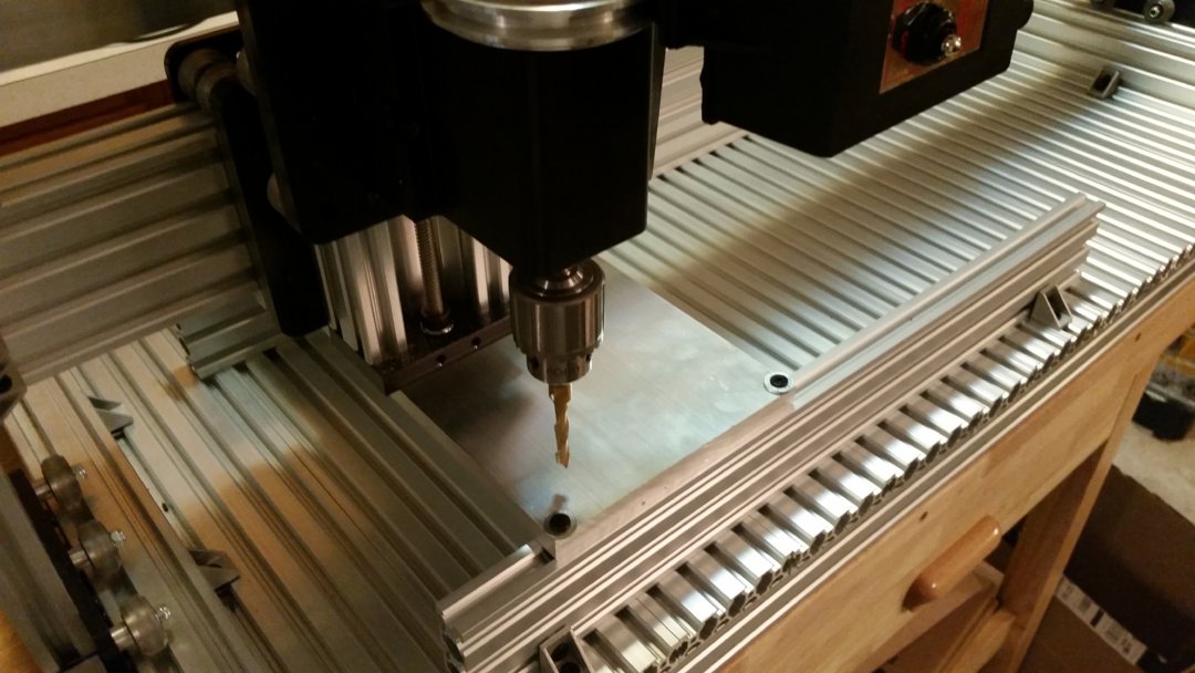
The slots in the bed allow for various stock mounting options. In the pictures below, two 20 x 60 x 500 mm V-rails prop the work piece up vertically to allow the end mill to pierce the stock without cutting the bed. The work piece had four 5 mm holes drilled into each corner with a drill press and then mounted to the rails with the standard Open Builds 5 mm low profile machine screws.
The machine has gone through several iterations, especially with the spindle. The first iteration used a BOSCH colt router but there were issues trying to buy the right collets for it. I then attached a water cooled 10,000 RPM spindle but could not find the right adapter to connect the hose to the pump. Tried the air-cooled spindle but the aviation connector and VFD cable didn't fit together very well. I then gave up on the high speed spindles and went with a DeWalt router, but didn't like being stuck with 1/4" or 1/8" end mills and really wanted the option to use a Jacobs chuck and gear cutting arbors.
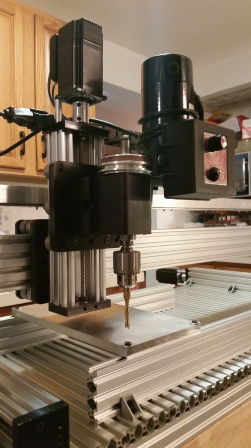
The Sherline headstock in the latest iteration just seemed like a no-brainer. The Sherline spindle is affixed to a Sherline lathe riser block which I drilled and tapped with M5 screws to an extra large gantry plate. The Z-axis actuator uses an extra large gantry plate as well, and the two can be mated together at a 90 degree offset with 12 mm M5 screws. Inherent in the spindle and riser block combination is the ability to lock the spindle in at arbitrary angles if that ever becomes useful. For normal operation, there is a key that makes sure the spindle stays locked in at 0 degrees tilt.
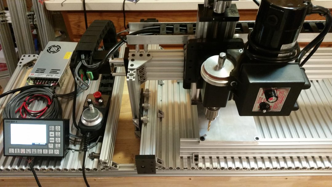
The motors used on the axes are JMC iHSS57-36-20 closed loop stepper motors with built-in drivers. They are controlled by a DDCSV1.1 4-axis offline CNC controller with MPG pendant. The cabling to the motors is shielded security wire from Home Depot. The power uses its own 2-wire cabling while the step/direction cabling is shielded with 4 wires. The motors and controller all run off the same 24V Mean Well power supply.
A fair amount of effort went into trying to make the X-axis drag chain nice and neat. It sits in a U-channel that hovers above the X-axis actuator. The channel was formed by taking two L-channels and a flat piece of aluminum from Home Depot and fastening them together with rivots. Holes were drilled at the ends for M5 screws to go through the U-channel and then 40 mm spacers to meet up with T-nuts in the actuator slot. The same drag chain was used for the Y-axis though that was mostly thrown in at the last minute.
Instead of cutting the 1500 mm V-rails short to match the size needed for the bed, they were left at full length and a table area was created with more 20 x 80 x 500 mm V-rails for the controller and power supply. The V-rails forming the bed and table are held down using 2-hole L-brackets underneath. To make the bed as flat as I could, the V-rails were attached upside-down on my kitchen counter-top with two other 1500 mm V-rails standing up vertically underneath those. I had to loosen things up when I went to attach the end pieces because I didn't do anything to ensure the 1500 mm rails were parallel to each other beforehand.
And the first part is a success!

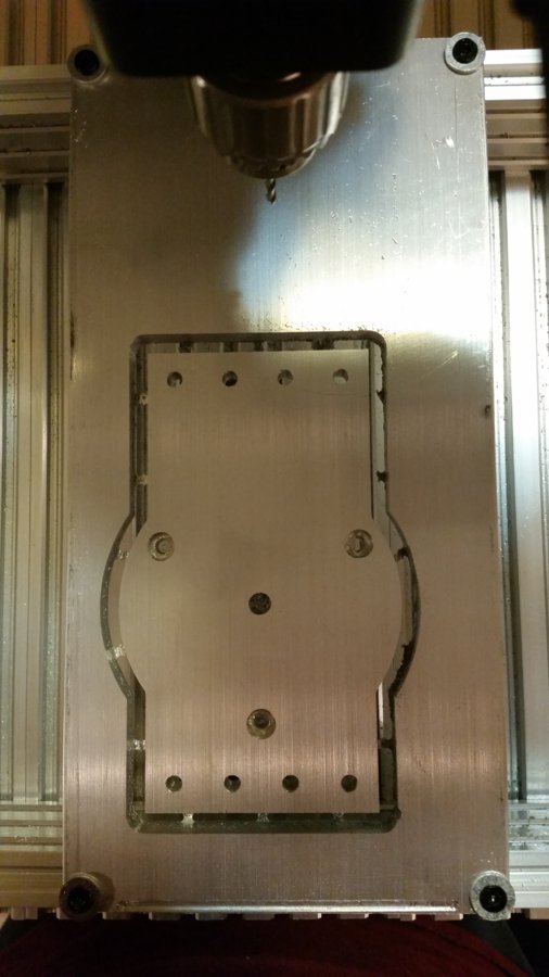
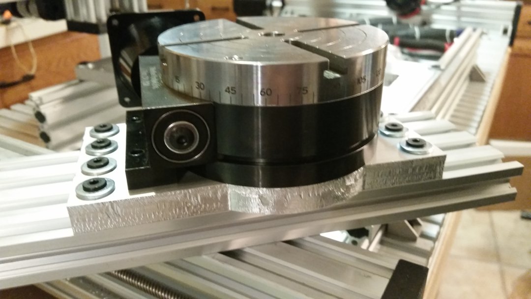
I got most of the way through the outside contour and the first bit broke off as it approached the first tab. I reran the program from the beginning with a new bit and out came a viable part! The surface finish is rough, but it is fully functional. I cut the tabs, deburred it and started assembling. I now have a plate I can use to attach a Sherline rotary table to a 20 x 80 V-rail!
And now I have to clean up all the aluminum dust in the kitchen...
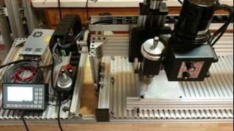
Sherline C-Beam with Offline Controller and MPG
Build in 'X/Y Table Style CNC Mill' published by James Evanko, Nov 23, 2018.
This is a C-Beam based router with V-rails used for the bed, a Sherline spindle with Jacobs chuck, closed loop stepper motors on every axis and an offline 4-axis CNC controller. A U-channel was created to guide the drag chain on the X-axis.
-
-
Build Author James Evanko, Find all builds by James Evanko
-
- Loading...
-
Build Details
- Build License:
-
- CC - Attribution - CC BY
Reason for this Build
Help with making custom aluminum plates to join imperial and metric components together.Inspired by
OpenBuilds C-Beam Machine XLarge and OX, but ended up a lot like the Lead CNC -
Attached Files: