
Basic Specs
Based on: Kyo's CBeam Sphinx
Print Area: 365mm x 610mm
Cost: $500-1000
I've been hijacking Kyo's Sphinx thread for a few weeks now, so I decided to just go ahead and spin this into a build. I'm in the process of building my first CNC, and after spending a few months eagerly researching designs, I fell in love with the Sphinx. The features I was looking for were:
Some of the mods I've made in my design (updated with results):
- Flexible. First and foremost, this will be about learning. I need a frame that can be tweaked, disassembled, and reassembled easily (ie. OpenBuilds)
- Relatively small. I have an old, sorely neglected Nova and way too many tools crammed in my tiny two-car garage, and now I'll need to make room for a CNC. It has to be small.
- Inexpensive. This is a hobby and I honestly have no idea what I'll use it for. I also have no idea what I'm doing, so I don't want to drop too much money into something that I'll undoubtedly want to remix later. I'm expecting to spend $500 or so to get it operational, and then more over time tweaking it (spindle, dust collection, better controller, drivers, etc.). I actually kind of like looking for clever ways to save money (which inevitably end up costing twice as much).
- Rigid. This will primarily be used with wood, but I do want to be able to cut soft aluminum (slowly).
I'll talk about each of these in more detail below and eventually document how each turned out. Here's the current design as of this afternoon. I'm hoping to start building in a week or two:
- Increased the Y axis to 750mm. Normally I see people increase the X axis length, but I wanted to be able to put this on a small table and easily see what was going on. I can sit and watch my 3d printer for hours, and I suspect I'll be just as enamored watching this. The downside is that this increases the length of a single rail carrying a majority of the machine's weight. CBeam's are pretty beefy, though, and I've added an extra 20x40 rail underneath the CBeam to hopefully reduce flex and torque on the Z axis. Update: no real issues with the increased dimensions. There is flex if you push on the front of the router. I don't have the tools to measure it, but it is significant. This will undoubtedly improve once I finish replacing my 3d printed plates, though.
- On a stock Sphinx, roughly 170mm of the 500mm X axis is unusable. To reduce this, I've moved the Y axis up and back 40mm by adjusting the side plates. I'm also planning to use 3/8" plates vs. 1/4" to help with any flex this change might introduce and just generally add some rigidity. Update: I actually feel like these plates are slightly better than stock. Moving the gantry back a little bit increases cutting area and seems to be slightly more balanced. Truthfully, it could probably be useful to go back another 20mm. I wouldn't move any further up, however.
- I haven't yet implemented this in my Fusion 360 design, but I plan to incorporate some limit switches into the plates. I'm hoping to go with inductive switches, but if I can't find room for them or get frustrated with the aesthetics, I'll fall back to micro switches. Update: I ended up not adding limit switches to the plates and instead 3d printed some mounts that attached to the extrusion in various places. I realized I've never show pictures of this, so I'll try to upload some soon.
- Instead of angle brackets, I'm going to make heavy use of blind joints. I used this technique on my 3d printer and was very happy with the results. I haven't been able to get a conclusive answer as to whether this significantly reduces the strength of the rail, though, so if anyone has any thoughts on that, I'd love to hear them ASAP (I'll start construction in a week or two). Update: I did use some blind joints in the bottom frame (the 20x60), but truthfully it was a pain. On my 3d printer, the aluminum was all 20x40 or 20x20. This made it much easier to keep everything lined up. I ended up 3d printing some 90 degree angle brackets and using these instead. They are plenty strong to keep everything rigid and square.
- I'm printing my own V wheels and anti-backlash nuts. Update: the 3d printed large wheels worked fine, but I had issues with the small wheels. They were just too loud and felt sketchy. I replaced the small inner wheels with Delrin openbuilds wheels, and used my 3d printed wheels for the large wheels. The verdict is still out on the backlash nuts. I initially thought I was having backlash issues because some holes were cutting too small. I believe this was being caused by a dull bit, however. After replacing the bit, everything cleaned up again.
- I'll make use of some other 3d printed parts to help reinforce and enhance the design. You can see an example in the endcaps found in the corners. I'll include any STLs here eventually.
- I'm hoping to anodize my plates to the orange color you see in the design. I've never done this, though, and it involves sulfuric acid so it could end badly.
3D Printed Wheels and Anti Backlash Nuts
I'll be frank (hopefully this doesn't get me banned). Openbuilds charges way too much for these wheels and bearings. You could easily spend 2x or 3x as much on a bunch of little plastic wheels as you do for 40lbs of aluminum rails.
My v-wheels are being printed using polycarbonate with a .05mm layer height and a .2mm nozzle. They're obviously not as strong or precise as what you buy, but I believe they will work.
Here's a shot showing two printed mini wheels. The back wheel was printed with .4mm nozzle and layer height. The quality of the left wheel was improved significantly by decreasing the layer height to .05.
The antibacklash nuts are printed in ABS and then tapped using a tap I made out of some scrap lead screw (props to Savvas for this technique).
Offsetting Plates to Reduce X Axis Waste
To reduce some of the unusable X axis in the stock Sphinx design, I've modified the gantry plates a little bit by moving the CBeam up and back 40mm increasing the cutting area slightly. I've also added holes for an additional 20x40 vrail which will be joined to the CBeam to hopefully add additional reinforcement. This will also have the added benefit of moving the wheels on the Z gantry plate further apart which should, I think, decrease torque slightly on the Z axis.
Here's the anticipated improvement to the cutting area:
![[IMG]](proxy.php?image=http%3A%2F%2Fi.imgur.com%2FdTbIlda.png&hash=4a3120029a44c2e600127a9a5f92b586)
And here's a shot showing the expecting impact (minor) on unusable space at the front of the machine:
Update from 5/1/2017 - Test Fit
Today was rainy and nasty, so I 3d printed all my plates, cut and tapped my aluminum, and did a test fit for the frame and X axis. So far, everything is going smoothly. The bad news is that my 3d printed wheels didn't work out. There was noticeable vibration compared to the openbuilds delron wheels. Too soon to say whether my backlash nuts will hold up over time, but so far they seem to be working well. I am a little worried that they will strip out eventually, though.
Update from 5/1/2017 - Models
I've had several people ask for models for the changes to the side plates, but I wanted to wait until I was able to test fit my changes. I haven't fully assembled the Z axis changes since I'm still waiting on a 20x40 rail, but I did print the models and verify that they assemble correctly. As always, though, your mileage may vary. Be warned that these are still *very experimental*.
In the models, I've included a reinforced and a non-reinforced version. The reinforced has an extra 20x40 rail below the Y access CBeam. I don't know that it's necessary, but I extended my Y access to about 740mm, and the extra rail is cheap ($13).
This requires slightly different side plates, and then taller Z access gantry plates. If you use the non-reinforced version, just use the standard Sphinx gantry plates.
One of the guys in my makerspace who owns a CNC has graciously offered to help me cut out my plates this week, so if all goes well I'll have some aluminum soon!
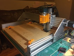
Update from 5/8/2017 - Assembled and Operational
![[IMG]](proxy.php?image=http%3A%2F%2Fi.imgur.com%2FXo50gBA.jpg&hash=1da5ce5df5ccf9504f8a48cc2a9f3bce)
I finished assembling using 3d plates and it's now fully functional. I haven't tried cutting anything yet, but it's drawing well (albeit slowly). I ordered a Makita 701c router and it should be here Wednesday. I'm going to try cutting some wood and MDF, and depending on how that goes, may go ahead and try cutting my plates out of aluminum.Here's a video of it running:
It seems really slow relative to other machines I've seen. The max feed rate is currently at 1000mm/min, but it really doesn't seem to be moving that quickly. My buddy has a shapeoko at 500mm/min and it's much quicker. I looked in the gcode and didn't see anything that was limiting speeds here. The total amp draw while all 3 axis are moving is around 1/2 an amp.
Update from 5/10/2017 - Anti Backlash Nuts and Makita Router Holder
I 3d printed my anti-backlash nuts out of ABS and they seem to be working fine, however, I was worried that they would strip out over time (or very quickly if I ever hit something solid). To help with this, I modified them to incorporate the brass nuts that came with my threaded rods. I only used one of these modified nuts per axis.
![[IMG]](proxy.php?image=http%3A%2F%2Fi.imgur.com%2F8ZvgWwM.png&hash=e66e230efb2b806ad55a48a0664a91cf)
Also, my router should arrive today, so I went ahead and build a holder for it. I couldn't find a Makita version for the openbuilds double gantry plate I'm using. It feels solid, but if it looks like I'm getting deflection, I'll either try to make something out of aluminum, or just buy the openbuilds holder and make an adapter for it.
I'll throw all these parts on Thingiverse and/or upload them here later this week.
Update from 5/10/2017 - First cut!
![[IMG]](proxy.php?image=http%3A%2F%2Fi.imgur.com%2Fi3FGwYR.jpg&hash=8b0d514dd92fbb9dacb8fbe16968c757)
All in all, it was a good day. I have a lot to learn, but I made good progress. Here's a video of me attempting an aluminum cut. It went surprisingly well, but ultimately failed because I don't have a good method of holding down the part. I don't have any doubt that I'll be able to cut my own plates once I get that resolved. I'm going to work on a wasteboard system next.
Update from 5/16/2017 - First Plate Cut
![[IMG]](proxy.php?image=http%3A%2F%2Fi.imgur.com%2FMARfmUY.jpg&hash=ae44e9e6b309ae83afb1b43de87249d1)
Well, this plate essentially cost me $70 (2 $25 bits + aluminum), but it was totally worth it. I never should have been using the expensive bits to learn, but I didn't have a 1/8" collet for my router and got impatient. Since then, I've found that the inexpensive 1/8" bits work fine at slow speeds. I may be doing something wrong, but they are significantly louder. I guess this is to be expected.
The most frustrating thing was that the tool breaks weren't while cutting. They were both caused by setup issues. One was prior to getting my limit switches installed and a bad home point. The other was caused by me setting my Z max speed too high and losing steps during a retract.
I'm sure I have many more painful lessons to learn, but I am starting to understand the process and it feels amazing when everything works the way you expect it to.
Update from 5/20/2017 - More Plates and Chamfer
I finished a couple more plates today for the X axis. Unfortunately I broke a couple more bits in the process, but they were the cheaper 1/8" end mills, so it was a little less painful.
I discovered that my 3d printed router mount is flexing way too much and is causing a lot of chatter if I get too aggressive. In a few cases, this has caused bit breakage. If I put pressure on the router, the chatter gets quieter. Guess I need to cut a holder out of aluminum or just break down and buy one.
I did my first chamfer today using a 1/4 spot bit. Worked well, but I got a little too aggressive with my depth and my speeds and got lots of chatter and some skipping. Next part I'll use a much less pronounced chamfer and slow it down.
My Z axis issue seems to be resolved, but I still need to finish my wasteboard so that I can get a more level cutting surface. There is some slight unevenness which is causing certain areas to take deeper cuts (especially w/ the chamfering).
Update from 5/22/2017 - Improved Makita Mount
I bulked up the design of my 3d printed Makita router mount significantly and it seems to be working much better. I'm getting zero chatter and have been able to increase my speeds significantly. I still need to get the mount choked up more closer to the router bit, but can't do that yet without moving my Z axis down. I've published the STL to thingiverse if anyone is interested.
Update from 5/26/2017 - Z Axis Upgrades
I haven't tested it yet, but based on a tip from Rick 2.0, I built and printed this new plate for the Z Axis late last night.It incorporates features from the Double Wide Gantry, and the XLarge gantry to allow for 4 internal mini wheels, and 6 large wheels on the outside. I'm hoping it will reduce slop a little bit on the Z axis. I've had issues with the mini wheels loosening up over time and they are a pain to retighten. This is less of a factor, but it's also a little shorter which should increase Z range a bit.
I'll do a test fit tonight and if all goes well, will try cutting it out tomorrow in aluminum.
Update from 5/30/2017 - Improved Z Gantry
Love the new XL gantry plate. It's not as streamline as stock, but way more rigid and easier to tweak since the eccentrics are on the outside. Here's a shot of the new gantry and a 70% finished side gantry plate I'm working on.
Update from 6/8/2017 - Wasteboard
Some wood inserts I ordered a few weeks ago came in today from China so I spent a few hours building a respectable wasteboard. It was my first time using 2 setups and Stock Constraints in Fusion 360 in order to be able to cut a board larger than the cutting area. It was relatively easy to setup in Fusion, but getting the board setup for the second cut was a pain. There's probably a trick to it, but I just moved the cutter a few mm above the surface and did a few tests until the cutter appeared to start and end in roughly the right spot. I need to do another one and put some inserts closer to the edges, but it's going to have to wait because the first one left me pretty demoralized (or maybe that's just formaldehyde poisoning from the MDF).
Update from 7/5/2017 - Aluminum Spinner
Haven't really had a lot going on with the CNC, but I did get all my 3d printed parts replaced w/ aluminum. The side plates are 3/8", and everything else is 1/4". Not surprisingly, it did make a huge difference in rigidity. I'm able to cut much faster with much less chatter. I am still using the 3d printed router holder,however, so that is still the weakest link. I've got an aluminum one on the way (hopefully).
This is aluminum spinner that I cut out of 1/4" aluminum. It was a 2-sided job, about a half-dozen separate operations, and took HOURS. Fun exercise, but 3D printing these things is so much easier/cleaner.
My general setup looked like:
I still have a disturbing problem cutting small holes in aluminum. When there are only small movements required to cut a small diameter hole, the bit seems to just kind of rock back and forth and not in a circular circumference. This obviously creates oblong holes. Usually a 2nd or 3rd pass will usually open it up, but sometimes it leaves artifacts. I suspect this is backlash on at least one of the axes, but I have no idea how to find/fix it. I would love to hear any ideas.
- Cut the 7.5mm pins used for aligning the different sides. I cut these 5mm deeper than the stock (into the wasteboard)
- Used a Pocket operation to roughly cut the holes for the bearings
- Used a contour to clean up the bearing holes
- Test fit the bearings. They were too tight, so ran another contour with a .1mm negative stock offset
- Used an Adaptive at .4mm to face the top
- Used a 2d Contour w/ 3 1.5mm tabs to trace around the part (seen from the video)
- Switched bits and used a 45 degree spot drill to Chamfer the top w/ a .5mm chamfer
- Unscrewed and flipped the part using a cut up carbon fiber arrow shaft as pins. Reattached to wasteboard and removed the pins.
- Faced the bottom using the same Adaptive Clear from step 5
- Chamfered the bottom using the same Chamfer from above. Not sure if this is the "right" way, but I mostly cut through the 1.5mm tabs w/ the chamfer operation.
- Removed the part and cleaned up the tabs w/ a dremmel.
For this part in particular, this caused slop in my pins, so when I flipped it and screwed it down, the backside was off by a fraction of a mm and my chamfer was off a bit.
Update from 7/18/2017 - New Carbide Bits
Quick update related to my last post. I started out using these 1/4" shank, 1/8" carbide bits for cutting aluminum. They worked amazing, but after breaking a few at $30 a pop due to stupid setup problems, I started using these cheap 1/8" HSS bits. This was pretty early in my learning process, so I didn't really have enough experience using carbide to know how inappropriate these HSS bits were for cutting aluminum. They were loud and dulled really quickly, but they mostly worked and at around $1 a pop, I didn't cry when they broke.Unfortunately I did have the issue mentioned above where small holes would often take 2 or 3 passes in order to open up to the correct size.
I'm happy to report that I've found a decent happy-medium. These $10 1/8" carbide bits seem to work almost as well as the expensive bits, but they cost a fraction of the price. They cut fast, are relatively quiet, and most important, I'm no longer having the issue w/ small holes cutting imprecisely.
My biggest mistake, obviously, was moving to aluminum too quickly. I wasted a ton of stock and bits with stupid setup problems, hardware problems, and improper speeds and feeds. This was partly impatience and partly me wanting to replace my 3d printed parts quickly before my machine tore itself apart. This was misguided because given some of the head-crashes I had, it's a miracle that I never seriously broke anything. This is a testament to the strength of Kyo's design and, surprisingly, 3d printed plates. While the path I went was more expensive, I learned a lot and it ultimately made me a better designer/machinist (I use that word very loosely).
Above is the plate I cut out with as a test for the new carbide bits. It's a shorter Z axis gantry plate that will hopefully give me an inch or so of extra Z axis movement.
Update from 7/21/2017 - New Z Axis Gantry Plate Installed
I had an unfortunate incident with my Meanwell 24v power supply last night. I dropped a heavy book on my desk, and immediately heard a loud pop come from my PSU/controller. I checked it with a meter and had no voltage on the output pins. I took it apart and replaced a fuse and a slightly blackened diode, but it's still dead. I tested the GRBL board with my bench PSU and it seems fine, so I have another PSU on the way.
I'm a little disappointed that it only lasted 6 months, but when I opened it up it had some aluminum shavings in it, so it's probably my own fault. While I wait for a replacement, I went ahead and swapped out my Z axis gantry plate. This smaller plate gives me about an inch of travel on both sides of the z axis. The downside is that this puts the outer wheels slightly closer together, but this doesn't seem to have affected rigidity.
![[IMG]](proxy.php?image=http%3A%2F%2Fi.imgur.com%2FMGuNVXn.png&hash=ba7c3ab11f6eb9539a5469a15357bcd7)
Salmon Sphinx 1.0
Build in 'Cartesian Style CNC' published by Brian Popp, Jul 22, 2017.
A tribute build based on Kyo's wonderful CBeam Sphinx. My hope is to improve on that build slightly, but to be honest, I'll probably just screw it up. I'll use this build to publicly document my failures.
-
-
Build Author Brian Popp, Find all builds by Brian Popp
-
- Loading...
-
Build Details
- Build License:
-
- CC - Attribution Share Alike - CC BY SA
Reason for this Build
This is my first CNC and the goal of this build is to learn and make mistakes. I'll be tweaking Kyo's design slightly, and will undoubtedly end up with a machine that won't cut burnt toast.Inspired by
Primarily Kyo's CBeam Sphinx, which is modeled after the original CBeam -
Attached Files:
![[IMG]](proxy.php?image=http%3A%2F%2Fi.imgur.com%2FTNGaEI9.png&hash=9c204b0391d15b9f974726429888081f)
![[IMG]](proxy.php?image=http%3A%2F%2Fi.imgur.com%2FnJQxF4r.jpg&hash=69598ef7f413ad56ef97ccd068ea62fc)
![[IMG]](proxy.php?image=http%3A%2F%2Fi.imgur.com%2FZhpVMc9.jpg&hash=890ffa4cdadf87cc6c26f89b7cccb538)
![[IMG]](proxy.php?image=http%3A%2F%2Fi.imgur.com%2Fdpm3YNU.png&hash=fa46b0baf7add2108565050d7d8c7f61)
![[IMG]](proxy.php?image=http%3A%2F%2Fi.imgur.com%2FA3aVEn5.png&hash=3cbfe82a20643af777c2096065b93280)
![[IMG]](proxy.php?image=http%3A%2F%2Fi.imgur.com%2FwI62VW2.jpg&hash=d9c9029fdf9cfc30d3ccb9295db23768)
![[IMG]](proxy.php?image=http%3A%2F%2Fi.imgur.com%2FXajMjd8.jpg&hash=40cb36247c446627033ca8544cb06710)
![[IMG]](proxy.php?image=http%3A%2F%2Fi.imgur.com%2FybgK0UR.jpg&hash=023f454c324cff4528d689a5d0c2e169)
![[IMG]](proxy.php?image=http%3A%2F%2Fi.imgur.com%2FuOUzqJf.jpg&hash=de85977cbc5083c35d99018ae9b5f694)
![[IMG]](proxy.php?image=http%3A%2F%2Fi.imgur.com%2FG8FHYdi.jpg&hash=35d28943860b62444a3b261b61b02f4e)
![[IMG]](proxy.php?image=http%3A%2F%2Fi.imgur.com%2FKE83Au8.jpg&hash=a1bc38bc3c0c9aedf4b4123f8de31ffb)
![[IMG]](proxy.php?image=http%3A%2F%2Fi.imgur.com%2FGAvbv6Y.png&hash=3e52bf5aa9b4f25114ec8d9ff831a69e)
![[IMG]](proxy.php?image=http%3A%2F%2Fi.imgur.com%2FnhgJo3P.jpg&hash=6bb90b03ad5c14a866562f82f425f3a6)
![[IMG]](proxy.php?image=http%3A%2F%2Fi.imgur.com%2FniRxK5l.jpg&hash=d0d2cca3d3197f3417d6df1ff1769049)
![[IMG]](proxy.php?image=http%3A%2F%2Fi.imgur.com%2FnVow1bu.jpg&hash=ed40e7c42a9df51e169f4ac8db09a04a)