
02/14/18 @ 12:30 PM EST
This build submission is complete.
Mechanical Build
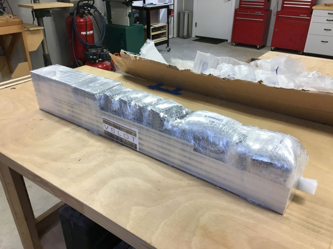
I started with the OpenBuilds C-Beam Machine XLarge mechanical bundle, with the optional (4) NEMA 23 high torque motors. The accompanying 44-page illustrated assembly instructions by Craig Mills and Mark Carew are detailed, complete, and easy to follow.
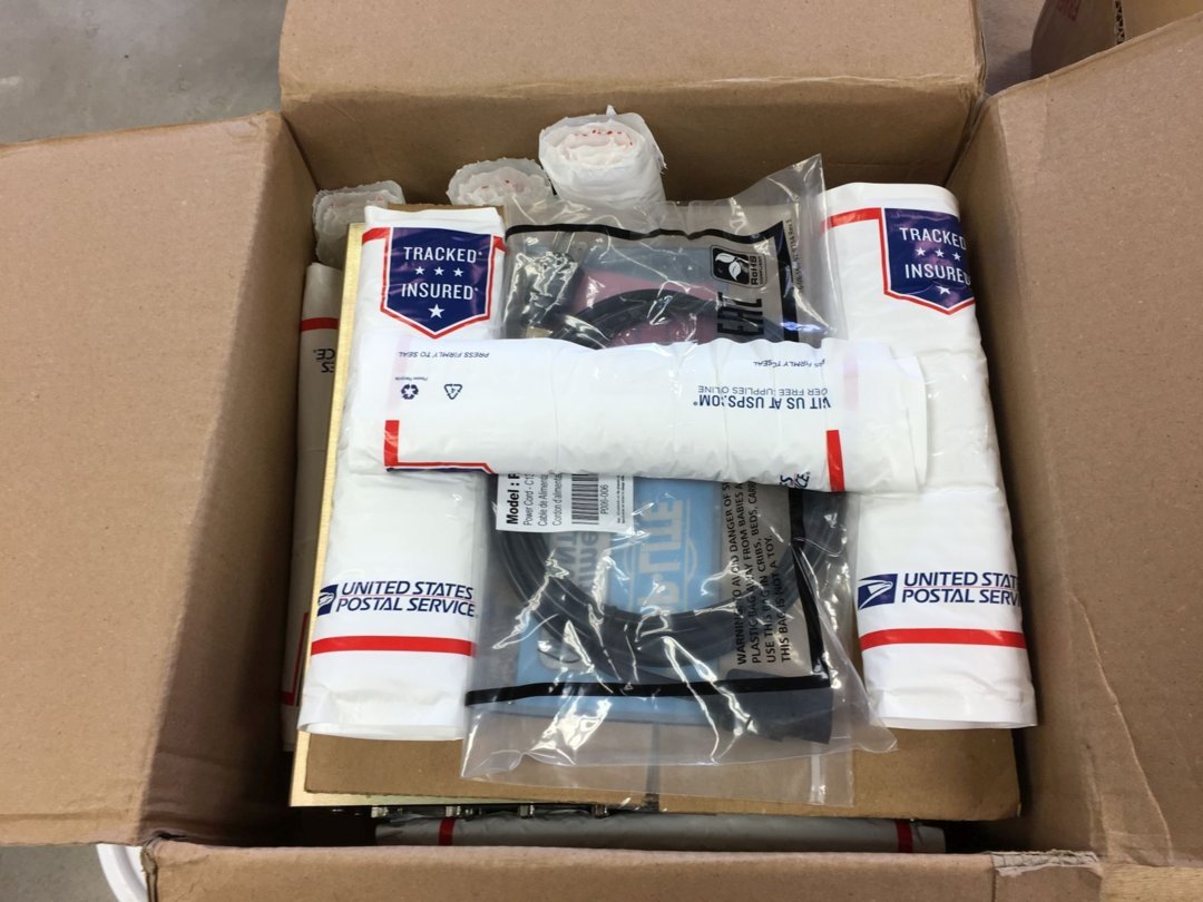
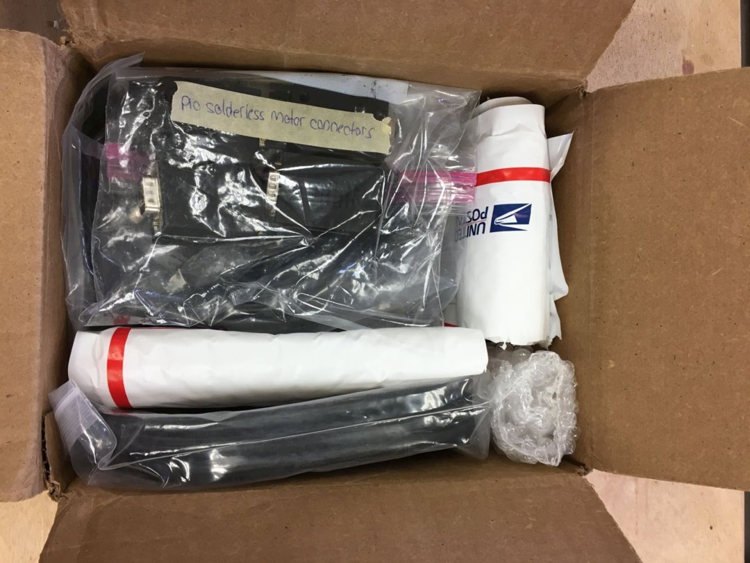
It was an exciting day when the mechanical bundle arrived in my shop. I was impressed with the care and thoroughness of the packaging. Everything arrived in perfect condition.
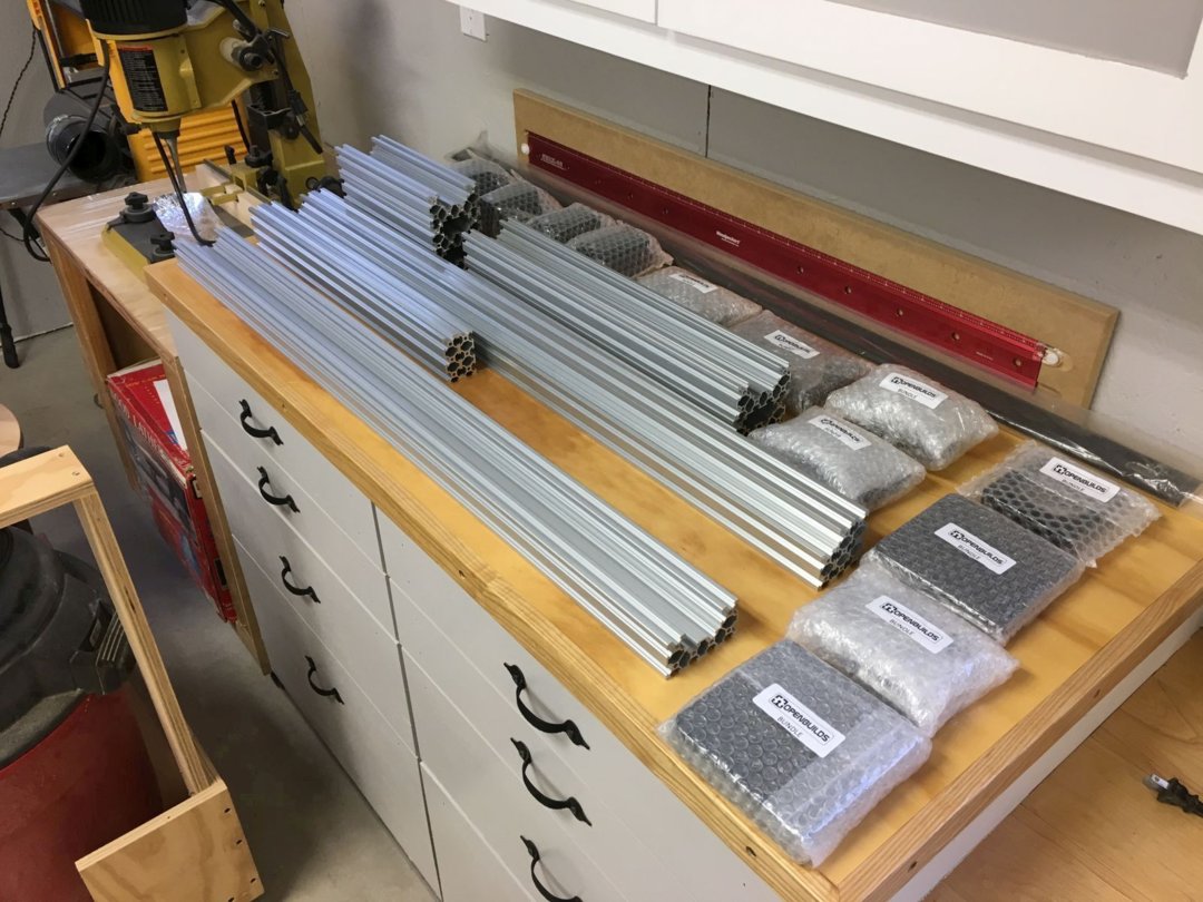
I inventoried all the components in the mechanical bundle against the enclosed parts list. Almost everything matched up with the parts list, with only a few fasteners short.
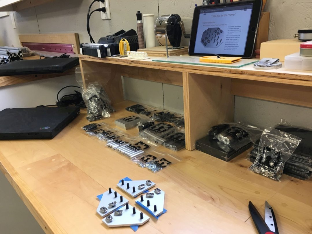
With the assembly instructions PDF running on my iPad, I started duplicating all the sub-assemblies illustrated. I won't bore you with pictures of all my sub-assemblies. They looked just like the ones in the assembly instructions!
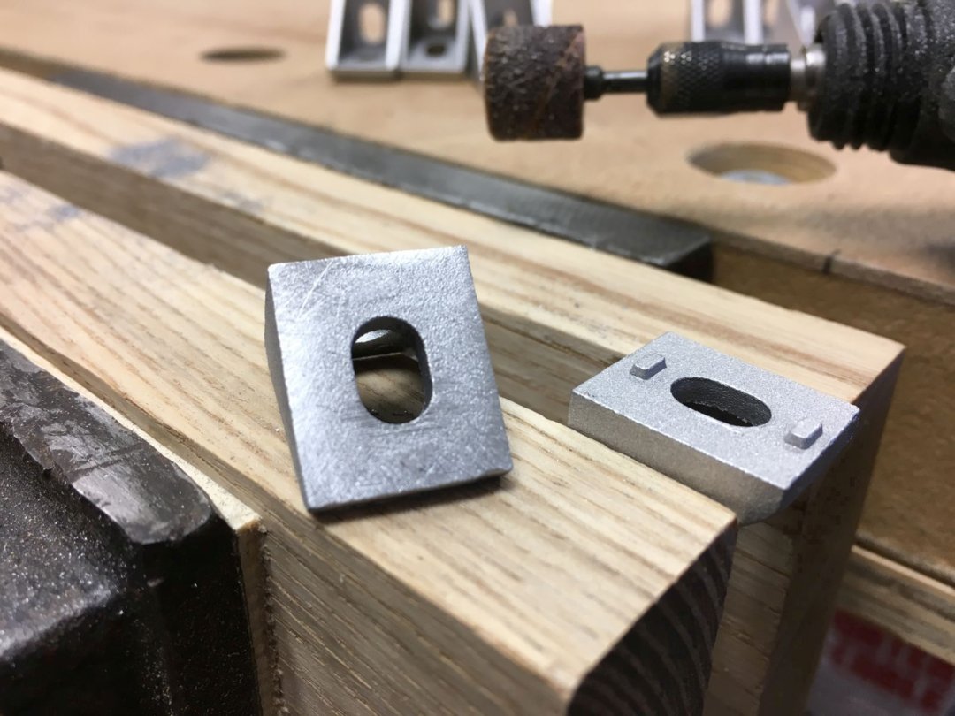
The assembly instructions call for modifying a number of the Cast Corner Brackets by filing off the alignment nubs on one side. I found that a small sanding drum on my Dremel tool made quick and clean work of removing the nubs, with the brackets clamped in my wood jaw vice.
While I supposedly had my good metal file out, the next step in the assembly instructions called for hand filing all the aluminum extrusion ends square, which they definitely were not, as received. Also, the pairs of 250 mm, 500 mm, and 1000 mm lengths of C-Beam and V-Slot needed to be exactly the same length. Since extrusion square ends and equal lengths were going to impact the overall accuracy of the completed machine, I was only slightly horrified at the thought of trying to achieve these accurate geometries with a hand file.
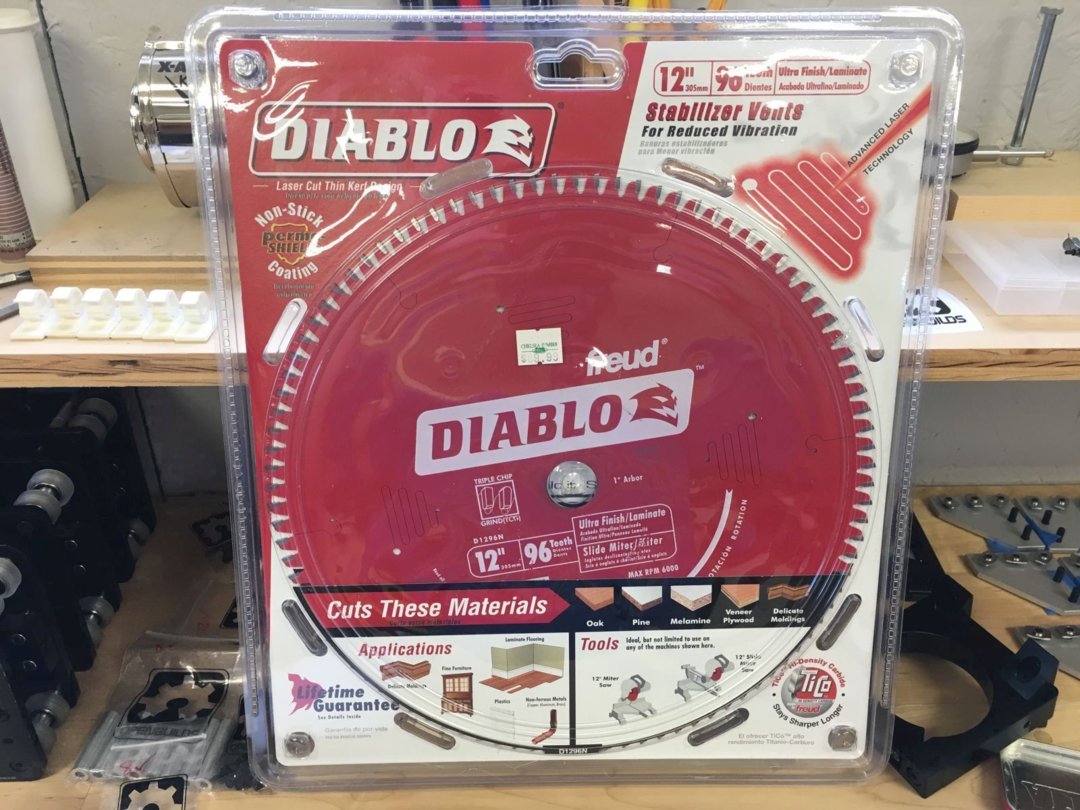
My solution was to purchase a 12 inch, 96 tooth, triple chip grind non-ferrous metal cutting blade for my DeWalt miter saw. Not cheap, but this blade gave me great results, and has come in handy many times since.
I tuned up my miter saw for the best squareness I could achieve with the fence, blade angle, and blade tilt. Then, using an adjustable stop system, I produced square ends and matched lengths on all the aluminum extrusions in a matter of minutes.
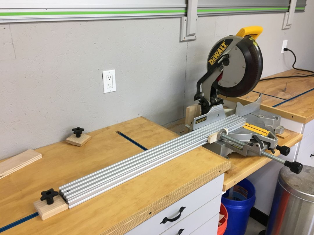
This video illustrates taking a skim cut to square the first end of the C-Beam extrusion.
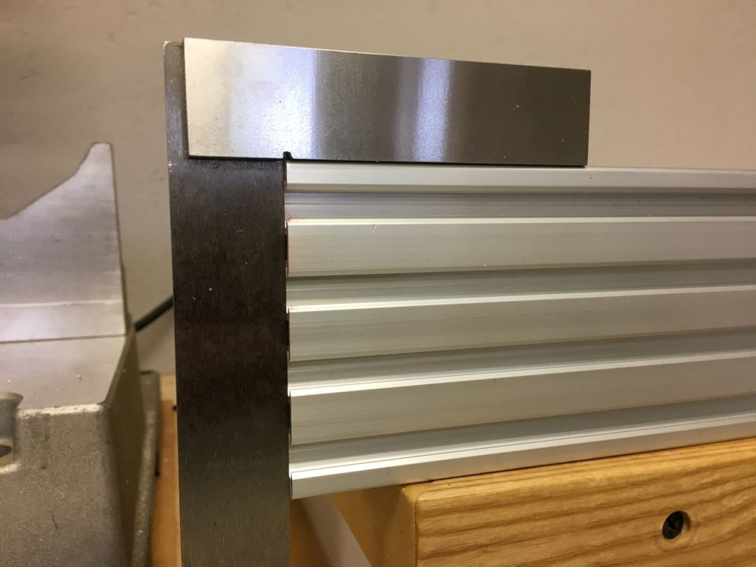
Checking the cut end with a machinist's square:
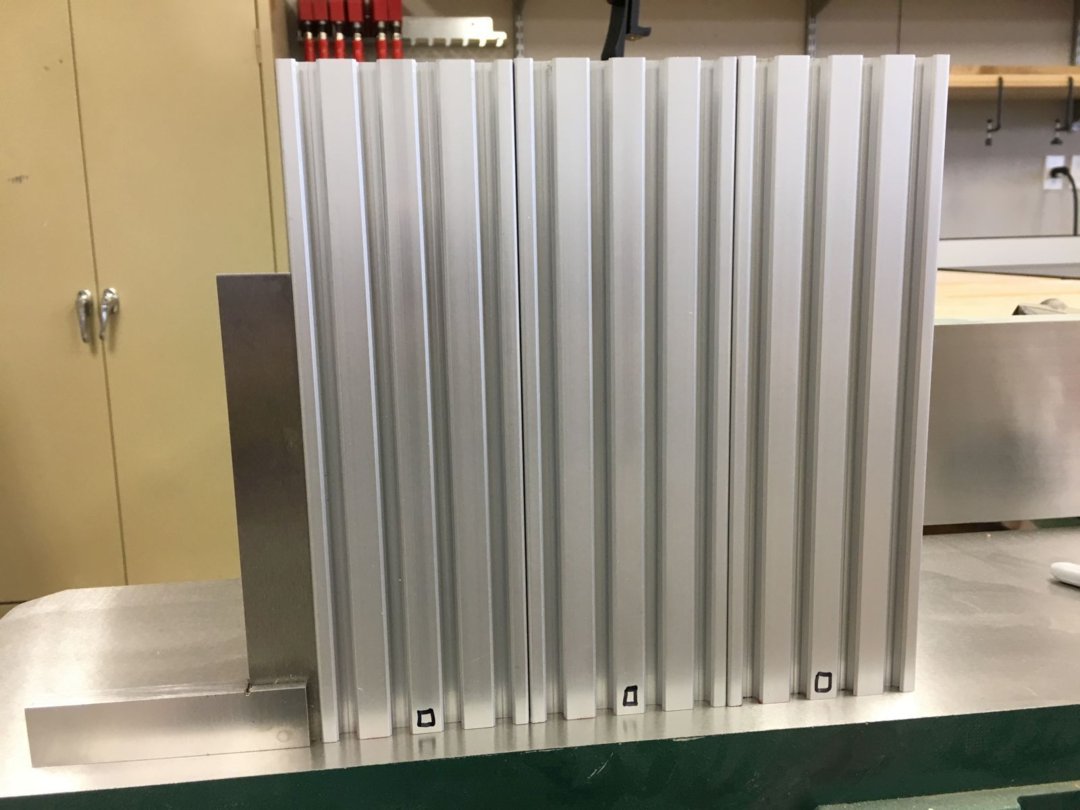
And finally, three trued up 250 mm extrusions, lined up on the outfeed table of my jointer:
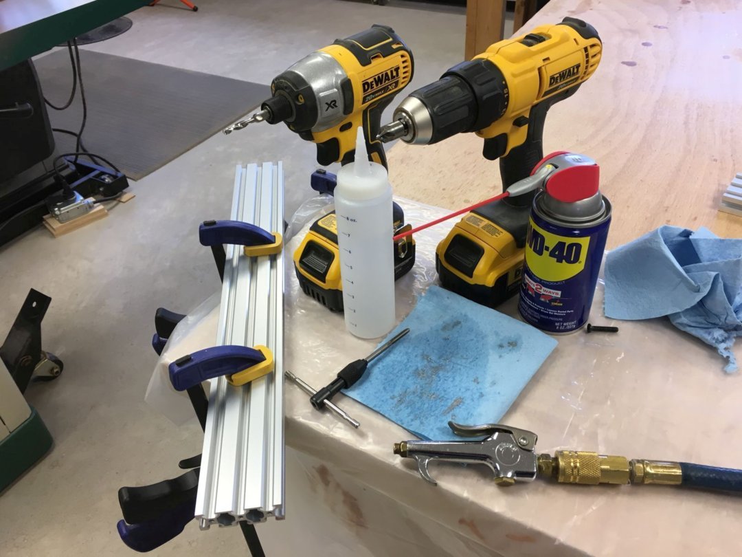
The next step in the assembly instructions called for tapping several untapped holes in several of the extrusions. (Why some, but not all, of the required holes were tapped as received remains a mystery.) As the instructions warn, aluminum is notoriously "sticky," especially when tapping small, fine threads. I used WD40 generously as a lubricant, and tried manually tapping the first hole. I quickly switched to the M5 Drill Tap from OpenBuilds, chucked in my impact driver. With small beads of sweat on my forehead, I slowly and carefully tapped the remaining required holes, and lightly cleaned up the openings with a chamfer bit.
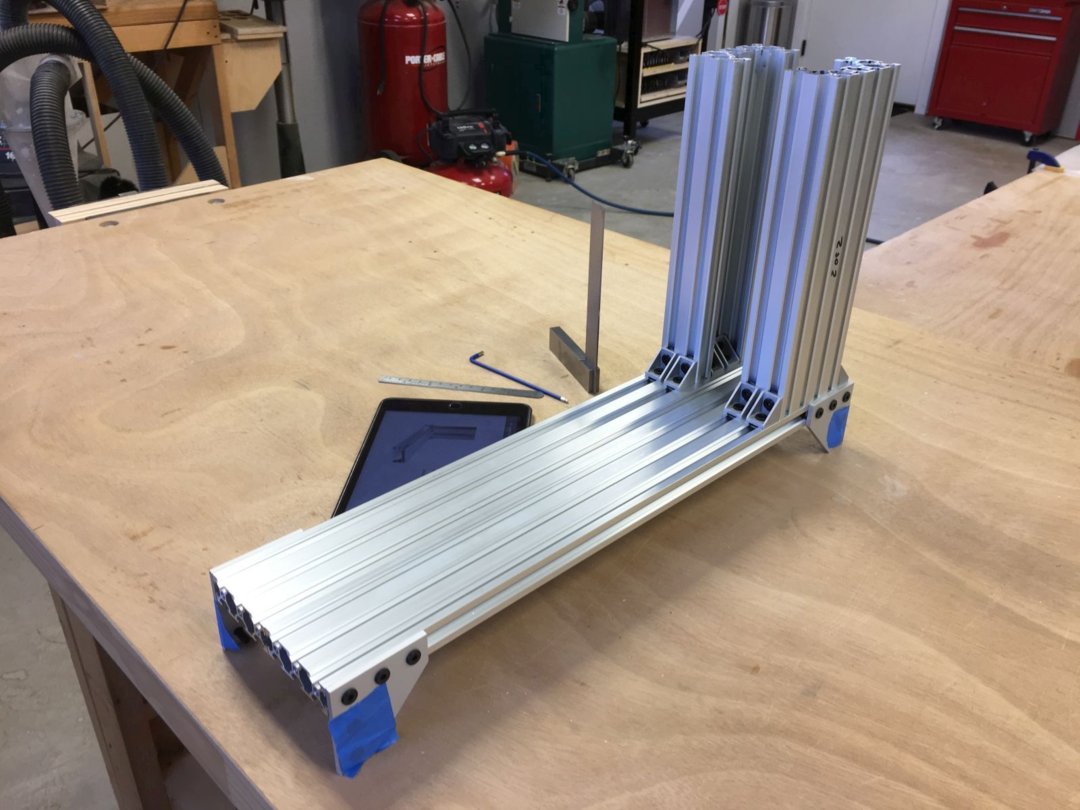
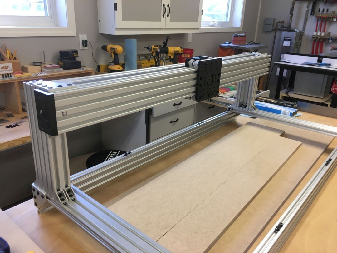
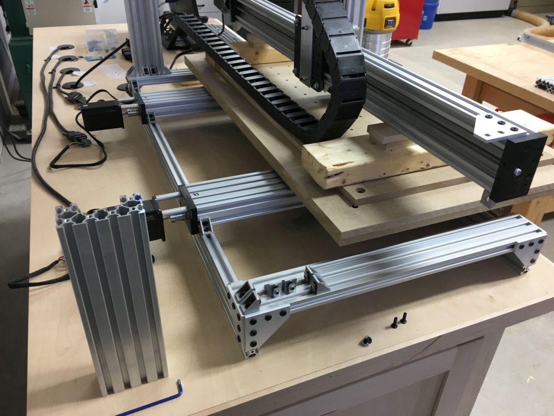
With all my extrusions trued and tapped, and all the connection sub-assemblies readied, it was time to build up the basic frame of the machine. The Frame Side Assemblies were first.
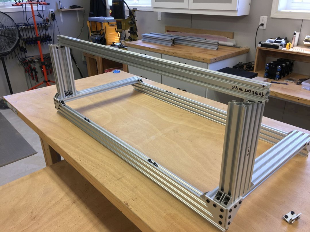
The two mirror image Frame Side Assemblies were then connected with the Front and Back Frame Assemblies. After checking everything for square, I used the assembly to mark the 1000 mm 20 x 40 V-Slot of the X-Axis Frame Brace for cutting to fit, ~960 mm.
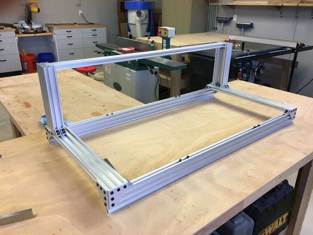
With the X-Axis Frame Brace cut to fit and installed, the machine's basic structure was complete, and it was time to move on to the MDF table assembly.
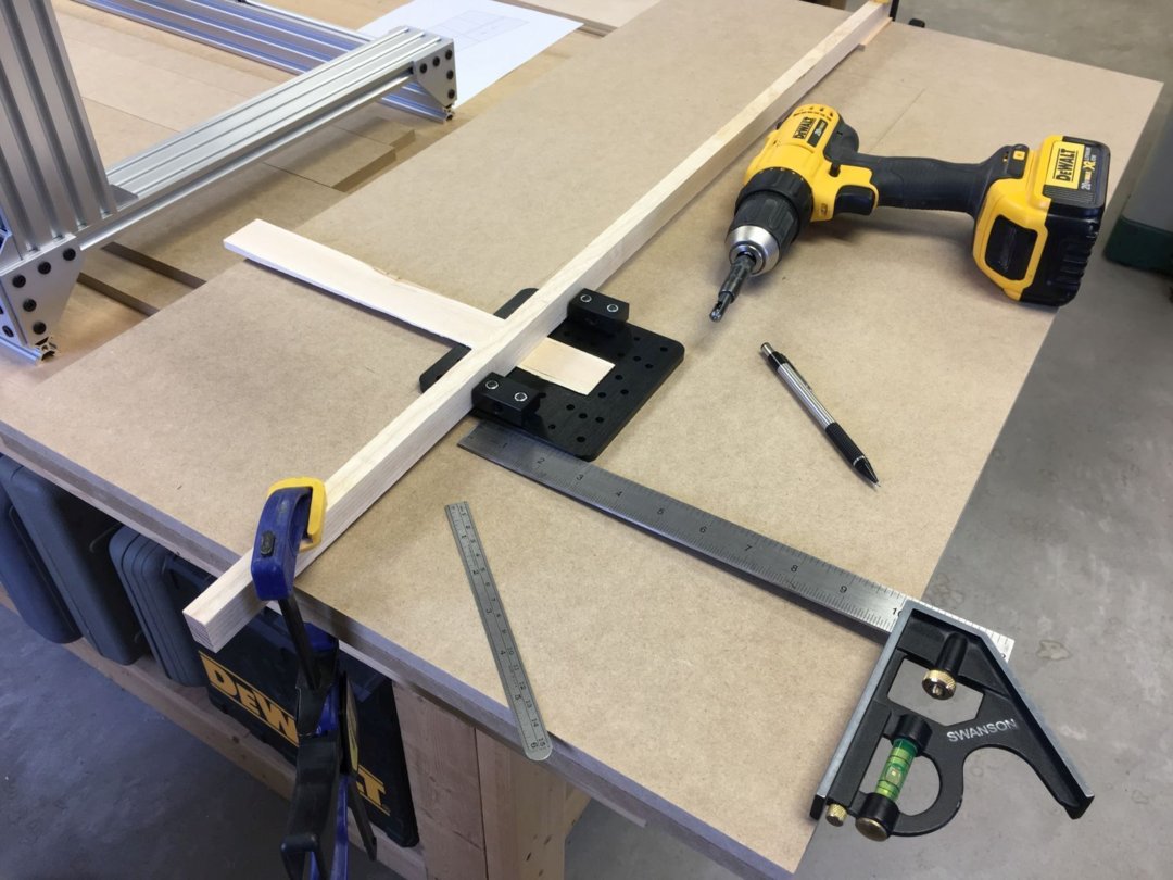
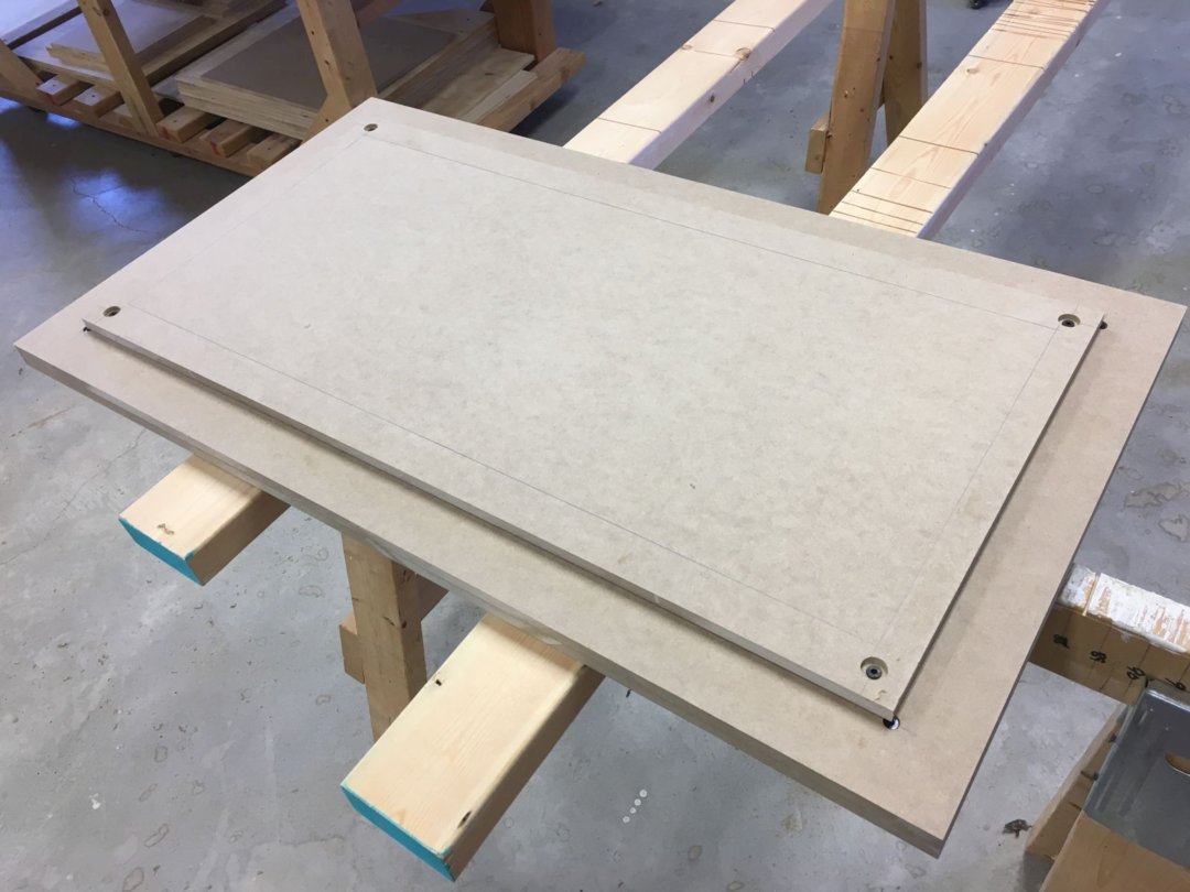
Since the Y-Axis Table and Spoilboard were made from MDF, being a woodworker, I was back in my element. Starting with a 4' x 8' sheet of 1/2 inch MDF, I cut the two 900 mm x 500 mm pieces to be glued together to make the table, along with four 800 mm x 400 mm spoilboards, one to use and three extras for later. Per the assembly instructions, I used a Y-Axis Gantry Plate and a Vix bit to transfer the mounting holes to the MDF table boards.
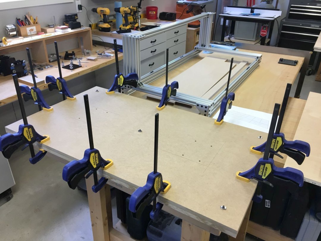
After all the holes were drilled, lots of glue and clamps assembled the 1 inch thick Y-Axis Table. (Norm always says, "You can never have too many clamps.")
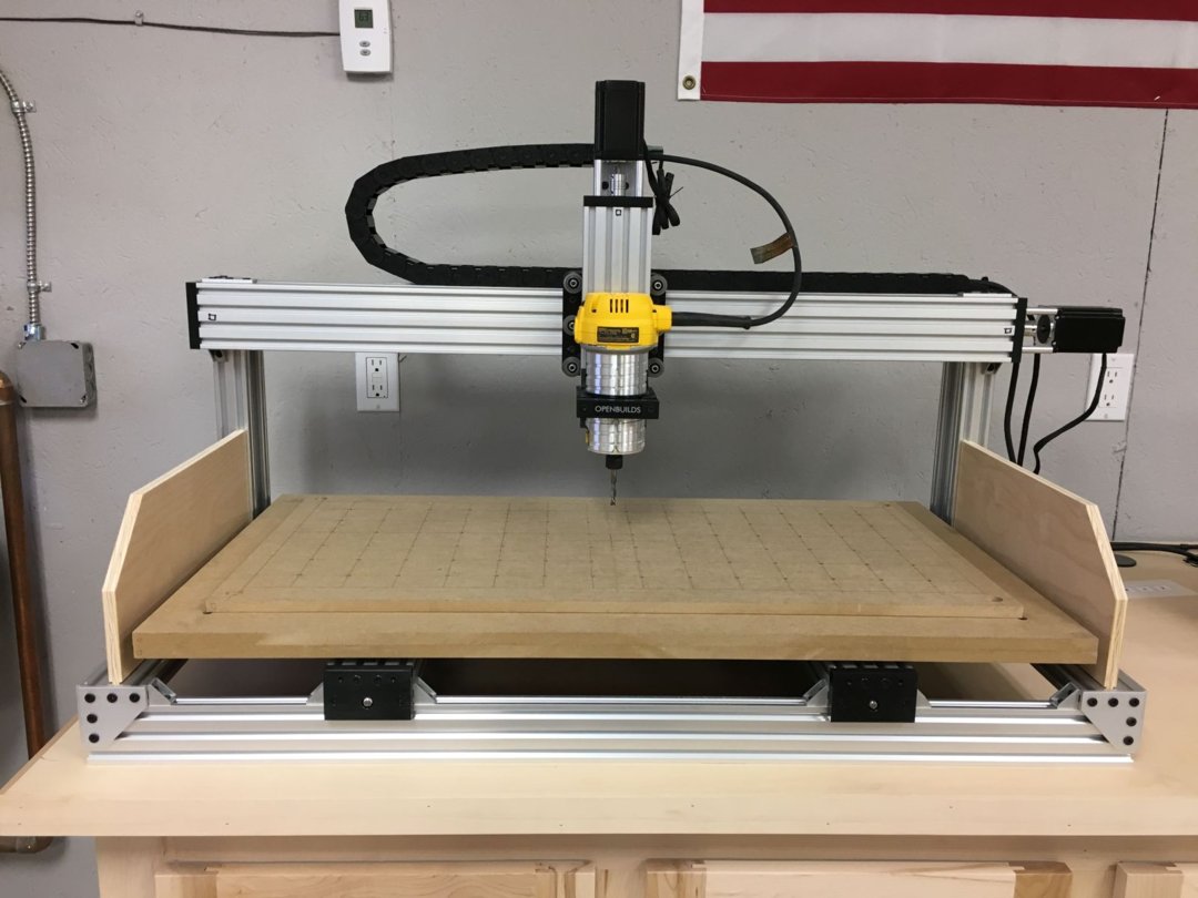
With the addition of the spoilboard (more on the clamping system I added to my spoilboard later), I was ready to move on to the four C-Beam linear actuator assemblies. Note that I marked the approximate X and Y travel limits on my spoilboard, 750 mm x 330 mm, or about 29 inches x 13 inches.
Wheels, Nut Blocks, and Spacers, Oh My! There seemed to be a million tiny parts to keep track of, but once again, the illustrated assembly instructions were easy to follow. It seemed appropriate to have a Fat Tire while completing these wheel assemblies. By the way, I found that a set of tweezers made handling the tiny parts a bit easier.
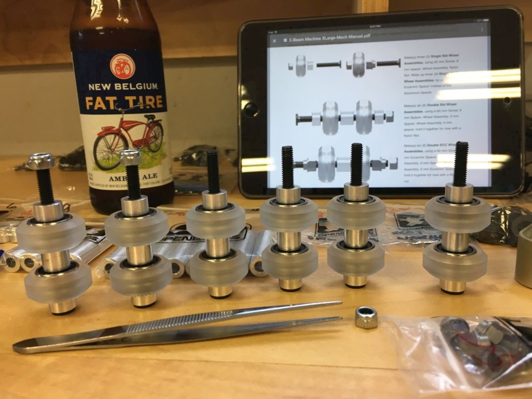
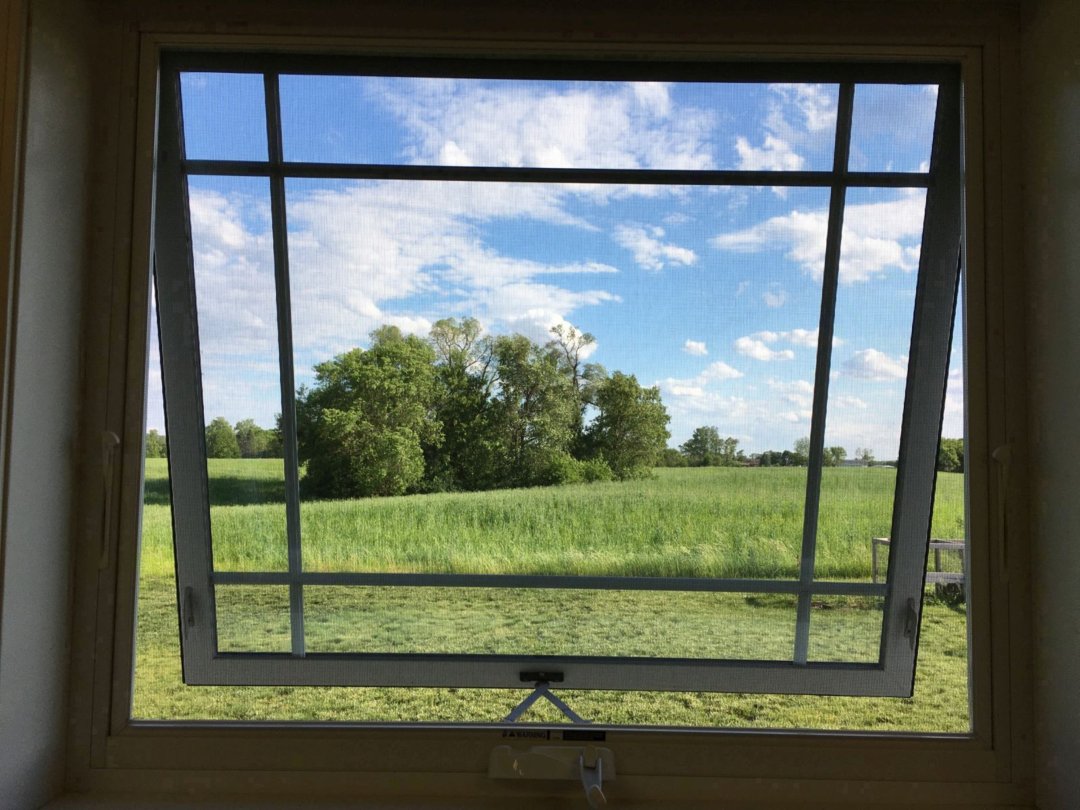
It didn't hurt to have a beautiful hay field to look at outside my shop window, either!
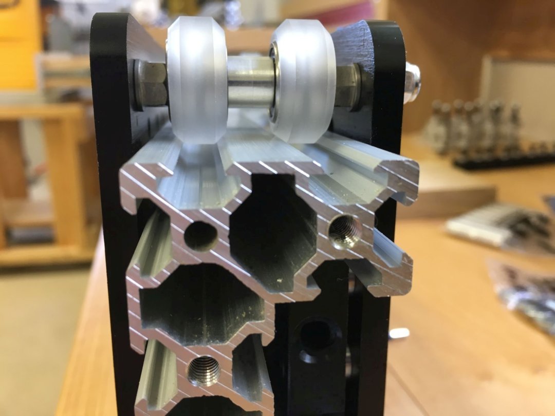
X, Y, and Z-Gantry assemblies were next, along with adjusting the eccentrics for a good fit in the v-slots of the C-Beam Linear Actuator rails. The assembly instructions go into a good amount of detail about getting the gantry wheels to fit the extrusions just right.
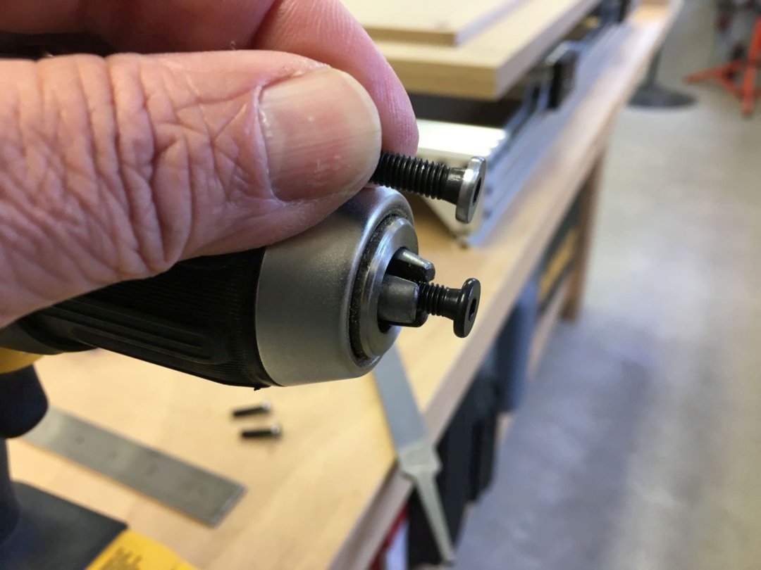
Once all the gantries were assembled, it was time to move on to the four linear actuator assemblies (1 X, 2 Y, and 1 Z-Axis Actuator). Here, I ran into a couple of small problems, but I filed and ground my way out of them. The first problem was that the heads of many of the 20 mm screws were too big to fit into the counterbores on the C-Beam End Plates. My solution was to chuck the screws in my cordless drill and file down the head diameters a bit.
The second small problem came with installing the 8 mm lead screws into the actuator assemblies. I didn't like trying to attach the Flex Couplings to the Lead Screws by making sure the tiny, tiny grub screws sat between the Acme threads of the lead screws. I didn't feel like I was getting a good connection between these two critical parts. The assembly instructions mentioned a "hack" of filing a flat onto the Acme threads under the Lock Collars, so I decided to grind longer flats that would accommodate both the Locking Collar screws and the Flex Coupling grub screws. Here's a short video illustrating how I ground the flats using a cutoff wheel and a steady hand!
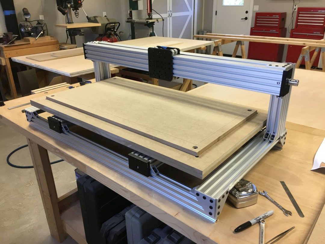
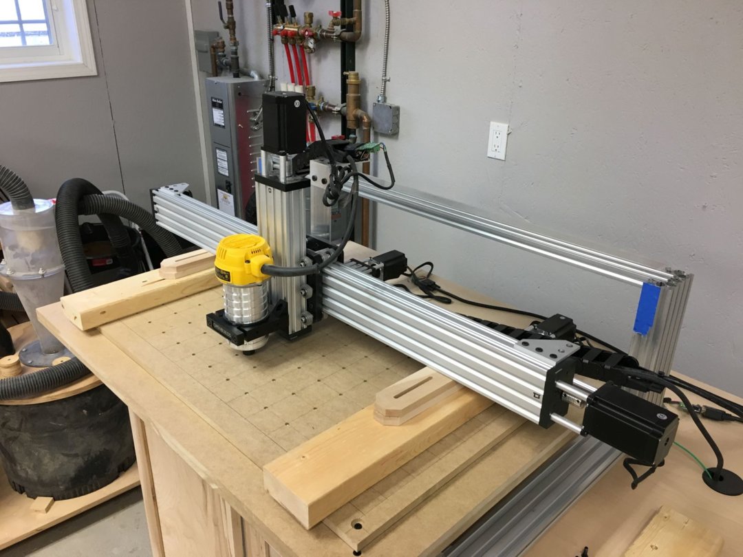
I carefully mounted the X-Gantry Assembly onto the machine frame.
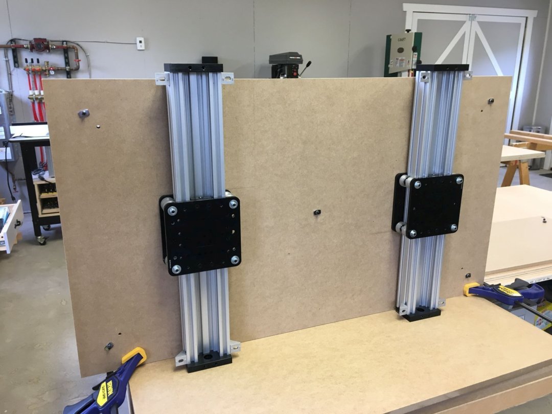
Then I set about mounting the two Y-Gantry Assemblies to the MDF Table Assembly. Working alone, I used some quick clamps to hold the table vertically so that I could access both sides. Once the two gantries were mounted to the table, I attached the whole shootin' match to the machine frame and attached the spoilboard.
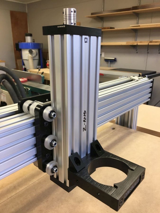
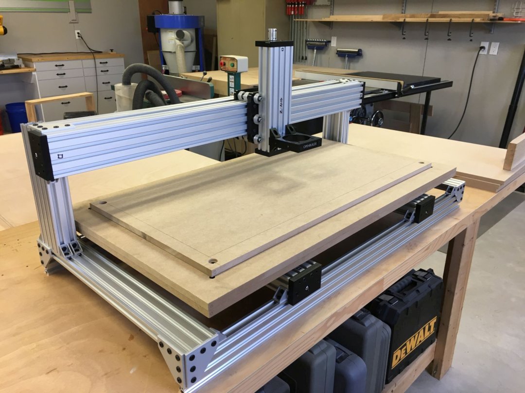
The very last step in the mechanical assembly was adding the Z-Gantry Assembly to the X-Gantry. Yee haw, I could finally start to envision three beautifully coordinated axes of motion from my very own, self-assembled OpenBuilds C-Beam Machine XLarge!
With the illustrated assembly instructions all completed, and no parts left over, I started to feel a bit alone. With a mechanical engineering and woodworking background, I had a lot more questions than answers about putting together a control system and software to breathe animation into this industrial work of art.
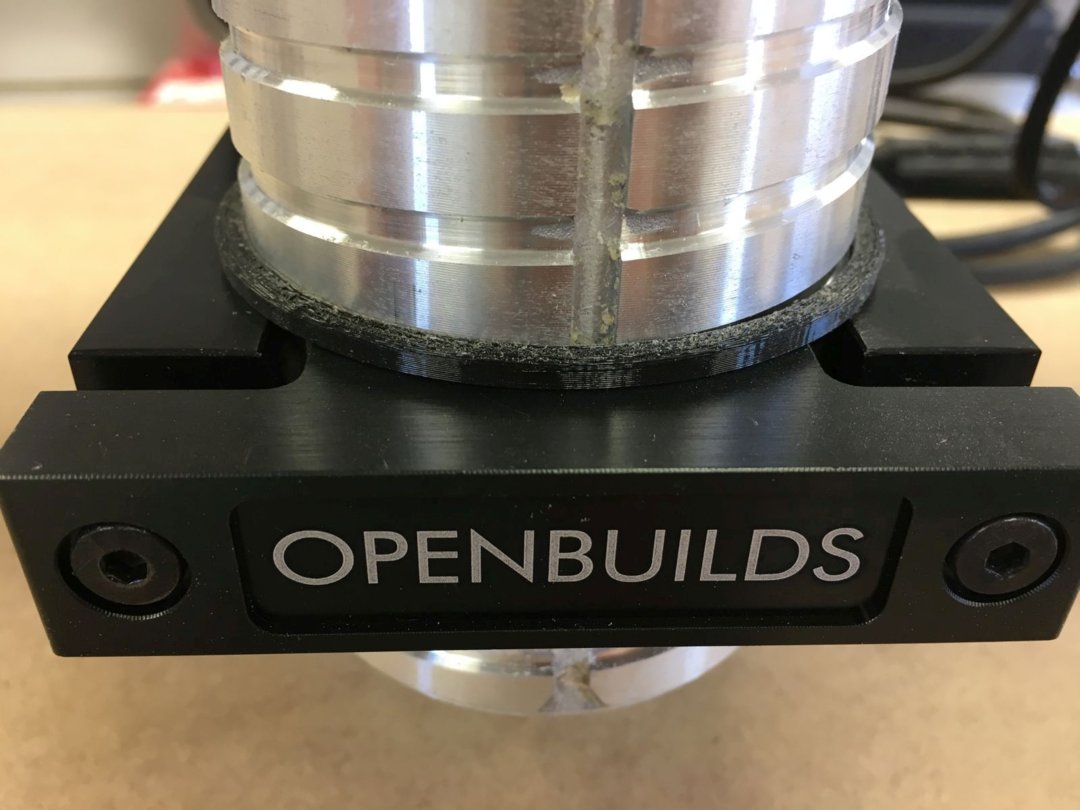
Fortunately, there was one more mechanical assembly step I could tackle. Even though the mount that came with the bundle was designed for a Bosch Colt router, my great experiences with DeWalt woodworking tools led me to decide on using an DeWalt 611 router. Because the DeWalt router body was slightly smaller in diameter than the Bosch router body, some shimming would be needed. Fortunately, my nephew Lucas has a couple of 3D printers, and he kindly 3D printed the exact shim that I needed, once I found the model for it on ThingVerse at Shim for DeWalt DW611 Router in OpenBuilds Router Mount. Thanks again to phil_from_seattle on ThingVerse for designing this shim, and to Lucas for printing it for me!
Control System
Oh boy ... with my mechanical build complete, it was time to dig in and figure out the hardware and software that I was going to need to put my three axes in beautiful, coordinated motion. The more I researched, read forum posts, watched videos, looked up individual components and software programs, the more I realized that there are probably thousands of combinations and permutations that would actually "work" to one degree or another. But without a background in systems engineering ... I didn't see how I was going to make the final downselect decisions on what to buy, and how to put it all together.
I won't bore you by attempting to list all of the components and software programs that I came across in my research. Rather, I will tell you where I ended up, and how I got there. First, I decided that to solve this case, I had to follow the ... information.
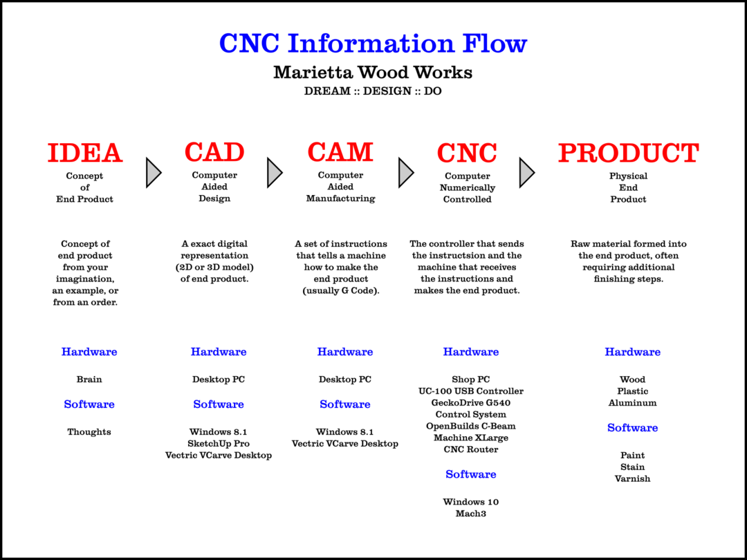
The graphic above summarizes where I ended up with my overall control system and software solution. Let me take a step back and tell you a bit more about how I got there. While watching many YouTube videos, I came across an overview of the 4-axis driver system I was considering, the GeckoDrive G540, on corvettguy50's YouTube channel, and I got my first introduction to Vince and his eBay store, eDealers Direct.
After watching several of Vince's videos on the GeckoDrive G540, on installing Mach3 motion control software, on the UC-100 parallel-to-USB motion control interface, and even on calibrating the stepper motors on my CNC router, I was convinced that I'd found someone who knew what they were talking about when it came to CNC control systems. I sent Vince an introductory email with a list of "Here's What I THINK I Need" and a request for feedback.
But did Vince send me an email back? Nope. Within a couple of days, he replied with a PERSONALIZED VIDEO, going over the list I had send in detail, making comments, suggestions, corrections, and providing options for me to think about. Vince said he had found that he could cover a lot more information talking on a video in much less time than it would take for him to type up a detailed email response. At that point, I was both impressed with Vince's knowledge and with his efficient customer service.
Long story short, over the next few days, Vince helped me fully spec out the control system he would custom build for me. I ordered it from him, and within a couple of weeks, my control system arrived in the shop.
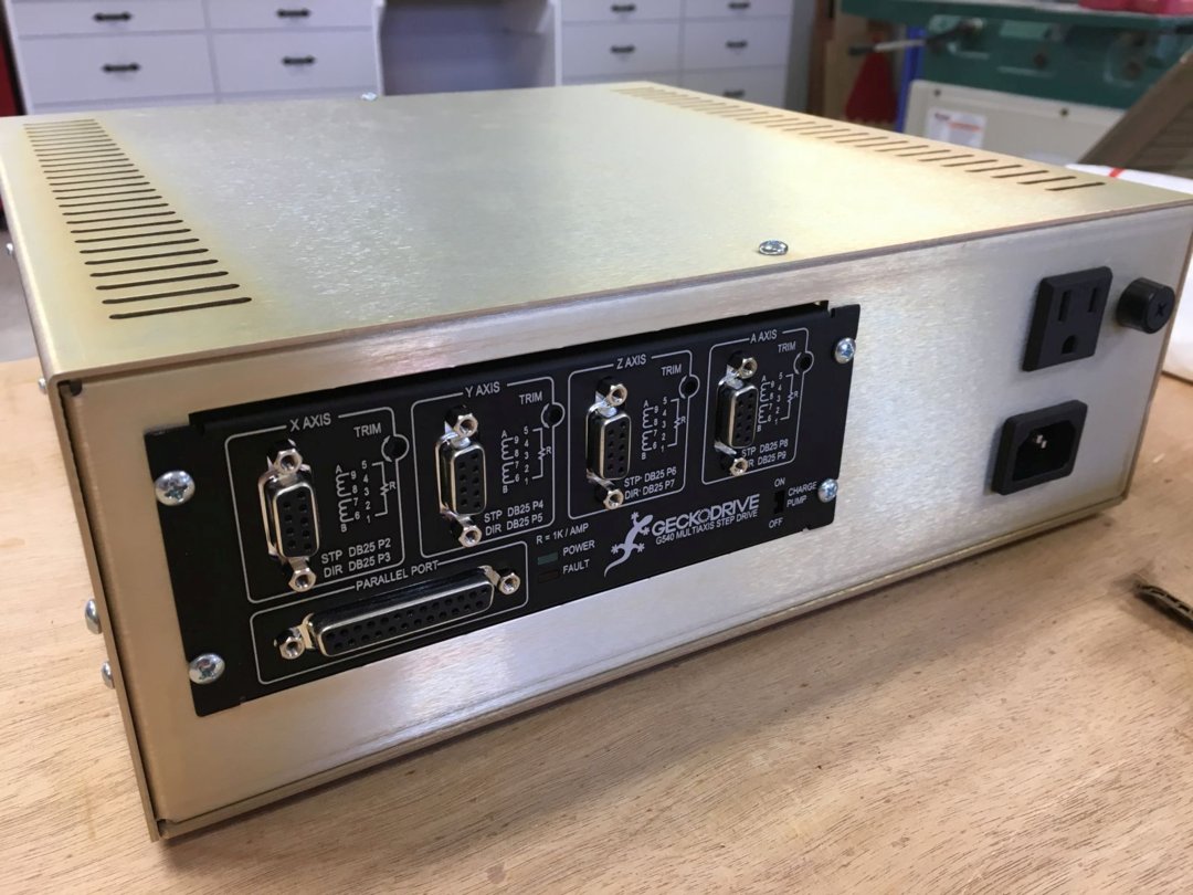
Here's a list of everything I received from Vince. (Everything is also listed in the Parts List section, too.)
Gecko G540 Motion Control Package:
G540 Rev8 (2017 Model Digital Stepper 4 axis Driver System,Aluminum Premilled
Enclosure (EMI Dipped) 48 VDC 12.5 A power supply, Integrated Cooling system w/
fan and heat sink, G540 DIY Labeling Kit
(4) DB9 20awg 13ft. Motor cables (Male/Female Connectors)
(4) DB9 Pro-Solderless Connectors
(4) Current Resistors Matched To Your Motors
UC-100 USB Motion Controller
Mach3 License
Before my control system arrived from Vince, he made and sent me an overview video, explaining all the features and details of the custom system he had built for me. Vince gave me his permission to share that overview video with you here. He explains the system a million times better than I could!
After the control system arrived, I made a temporary connection from my shop PC to the GeckoDrive G540 control system to one of my stepper motors on the workbench, and got my first motion. It was an exciting day at Marietta Wood Works! Here's a short video that will prove that Vince is much better explaining the electronics than I am.
Software
As my CNC Information Flow graphic (above) illustrated, there were three major software programs on which I needed to decide. Once again, I won't bore you with everything I evaluated, but rather, I will list the programs I selected.
Computer Aided Design (CAD)
I already owned a license for SketchUp Pro, the 3D modeling software that I am proficient with, and use to design all of my custom furniture-making projects.
The best software decision I made was purchasing a license for Vectric VCarve Desktop. I list it here under the CAD section because it has design capabilities, including vectorizing bitmap images, creating and editing 2D vectors, and some limited 3D model manipulation capabilities.
TIP: I found a nice feature of using both Sketchup and VCarve Desktop V9 in my design workflow: at least this version of the VCarve software will import native SketchUp (.skp) files directly. If you're working with SketchUp 2018 as I am, you do have to remember to save the SketchUp file to be imported as a SketchUp 2017 or earlier file format before you import it into VCarve.
Computer Aided Manufacturing (CAM)
I also list Vectric VCarve Desktop here under the CAM section because it also has robust toolpath visualization and generation capabilities. The toolpath visualization feature is so robust that you can see what your completed project will look like, complete with material textures and paint colors of your choice. It's also a great way to verify that your toolpaths will do what you expect them to do. VCarve has options to create G Code in many "flavors," to be most compatible with your particular machine control program. (I use the option for G Code with circular interpolation most compatible with my Mach3 CNC software.)
For my mostly hobby purposes, the Desktop version of VCarve was the most cost-effective choice of the Vectric software offerings. VCarve Pro and Aspire include more capabilities, but they also come with additional cost that I could not (yet) justify.
The Vectric Support site, including many tutorial videos, is a great resource for learning how to utilize their software to best advantage.
Computer Numerically Controlled (CNC)
In my early research, I read about the mature Mach3 CNC software for PC-based machine control, and how widely it was in use across many industries and DIYers alike. Because this software was originally designed to use a parallel (printer) port interface, which most modern PCs don't have anymore, I thought my choices were to either find an old PC with a parallel printer port, or find a different machine control software altogether.
It wasn't until I was watching Vince's (corvetteguy50 on YouTube) videos that I realized that adding the UC-100 parallel-to-USB controller interface to a GeckoDrive G540 4-axis driver system would allow me to use a modern PC running an up-to-date operating system with the Mach3 CNC software.
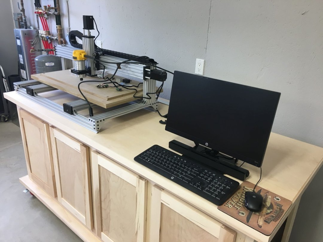
And that's exactly what I did. I've dedicated a small HP Pavillion PC running Windows 10 to be my Shop PC. It runs Mach3 like a champ, which sends my G Code instructions through the UC-100 USB interface to the GeckoDrive G540 which, in turn, tells all four of my NEMA 23 stepper motors just what to do!
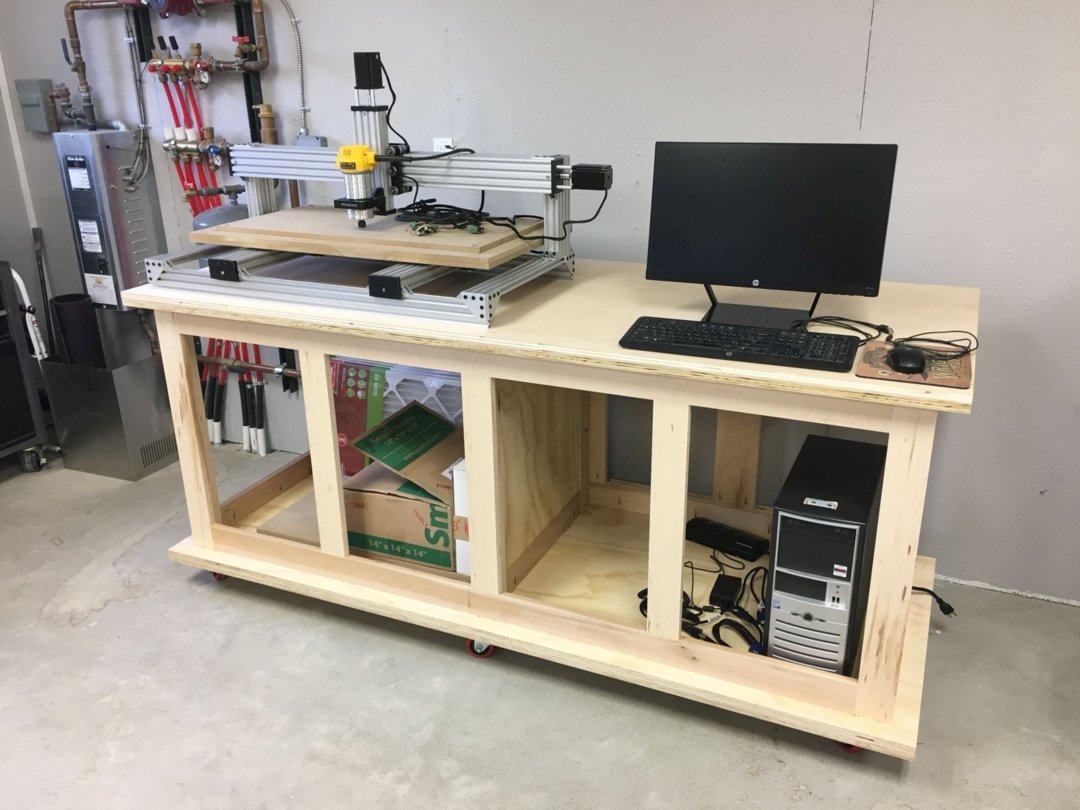
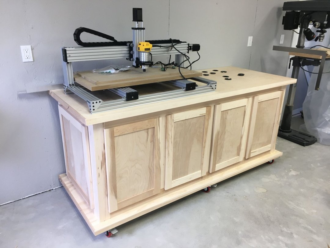
Cabinetry Design and Build
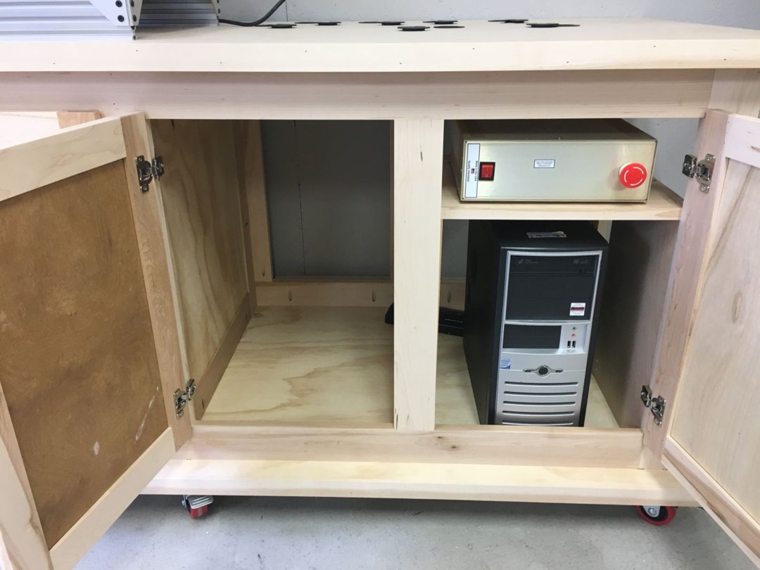
Some of the pictures above already show the cabinet I build to house my C-Beam Machine XLarge, monitor and keyboard, GeckoDrive control system, and HP shop PC. Because I'm mostly a woodworker, I'll show you a bit about how I designed and built this cabinet.
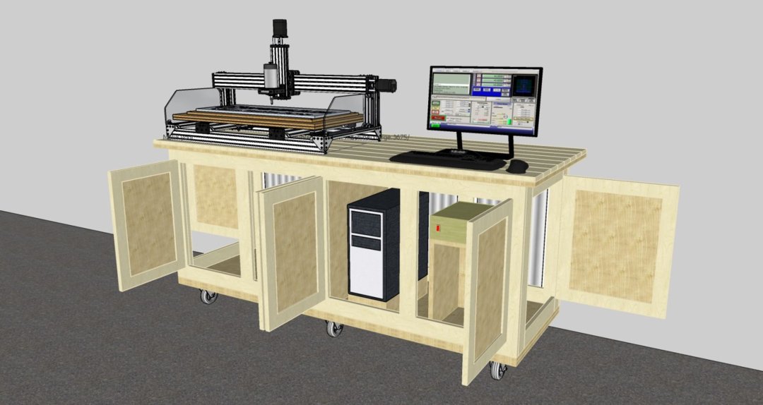
I've included my custom SketchUp design of this cabinet in the Files and Drawings section of this build, in case you'd like to build one for your shop. Here's a screenshot of my SketchUp model. You will see in the actually pictures that after I got a smaller PC (long story), I decided to position it directly under the control system. (The model of the C-Beam Machine XLarge is from OpenBuilds.)
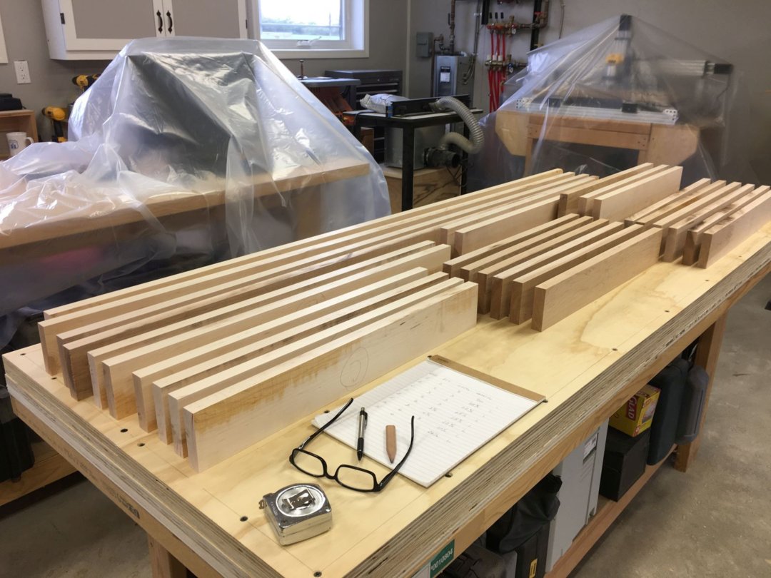
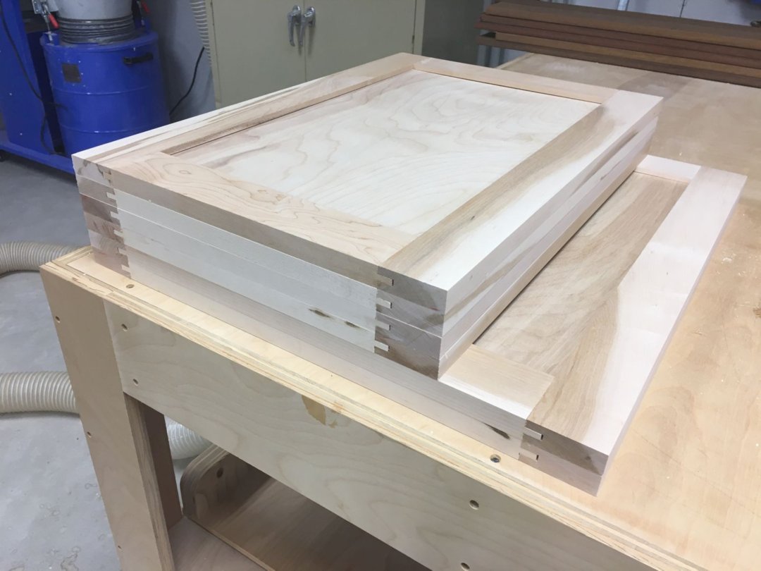
Here is the obligatory woodworking project initial picture of a pile of lumber, maple in this case, on top of two 3/4 plywood glue ups that formed the top and bottom panels of the cabinet:
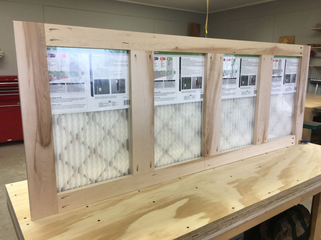
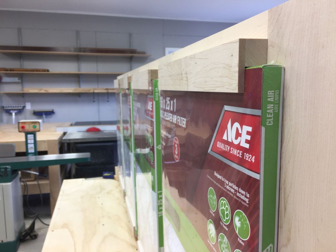
My main concern in the design of this cabinet was to protect the control system and shop PC electronics from the wood dust that permeates the shop on a regular basis, but to allow for some air flow to dissipate the heat those same electronics generate. My solution was to mount replaceable furnace filters on the back of the cabinet, to allow for an air exchange without admitting dust. I felt like the volume inside the cabinet was large enough that forced ventilation from the outside wasn't warranted. Here's the back panel sub-assembly, and yes, I remembered to remove the plastic wrapping from the filters before I put them into use!
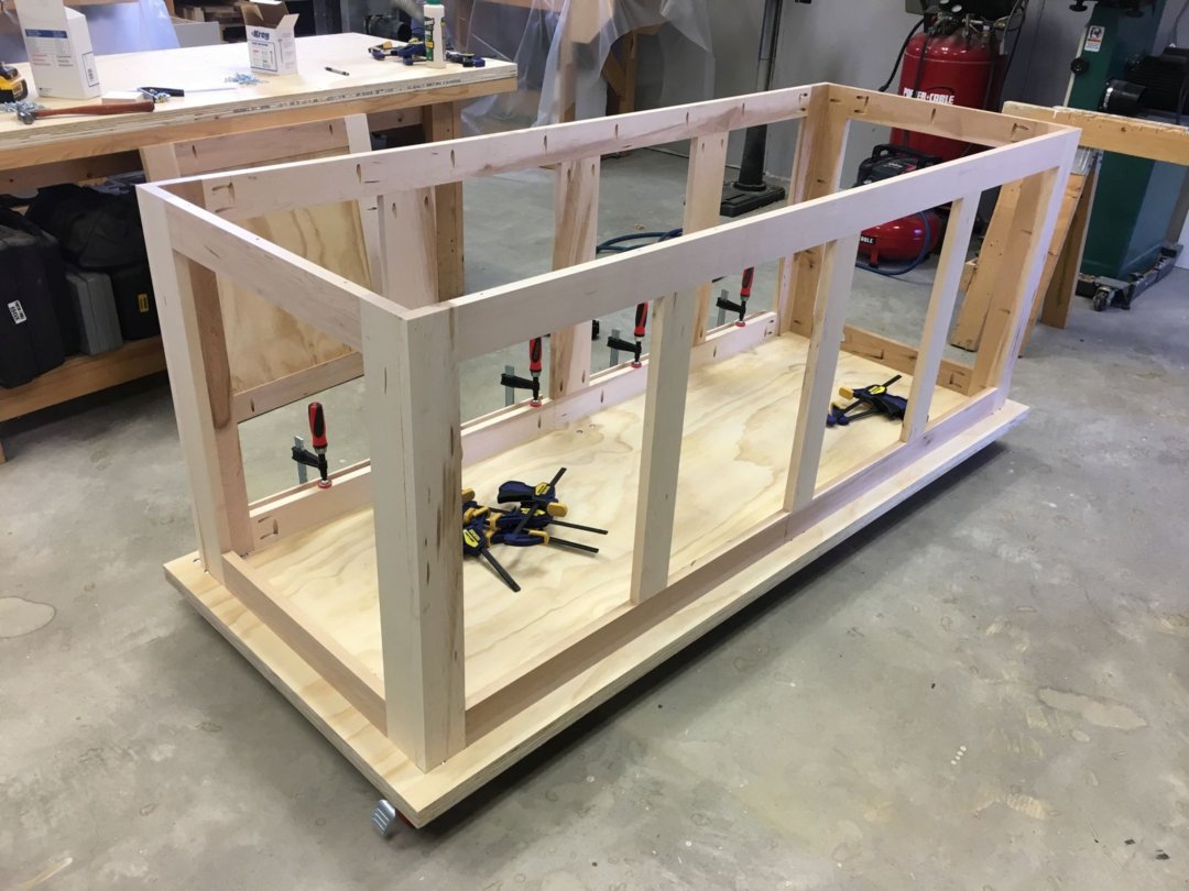
My second concern was access to all of the wiring that was going to be housed in the cabinet, so I decided to make all four sides as face frames, with four doors on the front and one on each end. With these doors, and slipping out one or two of the furnace filters, I had great access to all the wiring from every angle.
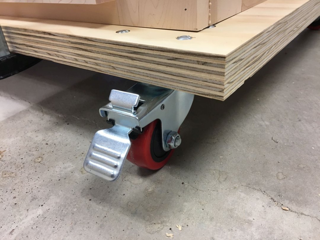
I sealed all the doors with weather stripping, and mounted six heavy duty, lockable casters on the base. Here are a few more pictures to illustrate.
Additions and Modifications
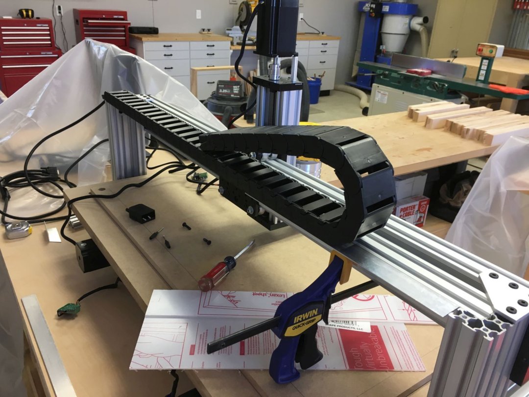
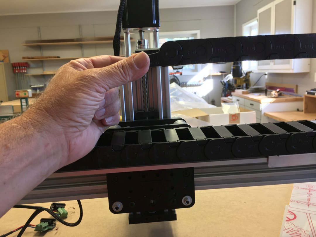
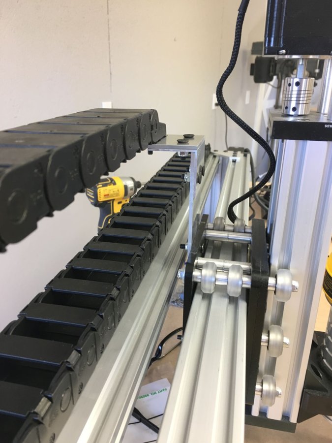
Cable Carrier
I needed a cable carrier for my Z-axis motor cable and for the DeWalt router power cable. I was worried about electromagnetic interference, running the digital motor control cable in the same track as the 110V power cable, so I checked with Vince at eDealers Direct, who had supplied my control system, including the motor control cables.
Vince reassured me that his 20 AWG motor cables were EMI shielded, so he didn't anticipate any problem with running it in the same track as the insulated power cable. Vince did point me to the video on his corvetteguy50 YouTube channel, on properly grounding the aluminum frame of my machine to provide a discharge path for any built up static or EMI charge. I followed his instruction and provided an earth ground to the frame of my machine.
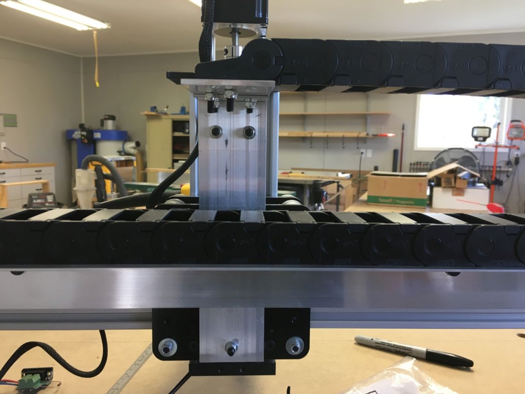
I used a length of igus energy chain Series 14 cable carrier (p/n in Parts List), some 1 1/2 x 1 1/2 x 1/16 aluminum angle, and some flat aluminum bar stock to build the cable carrier system illustrated below.
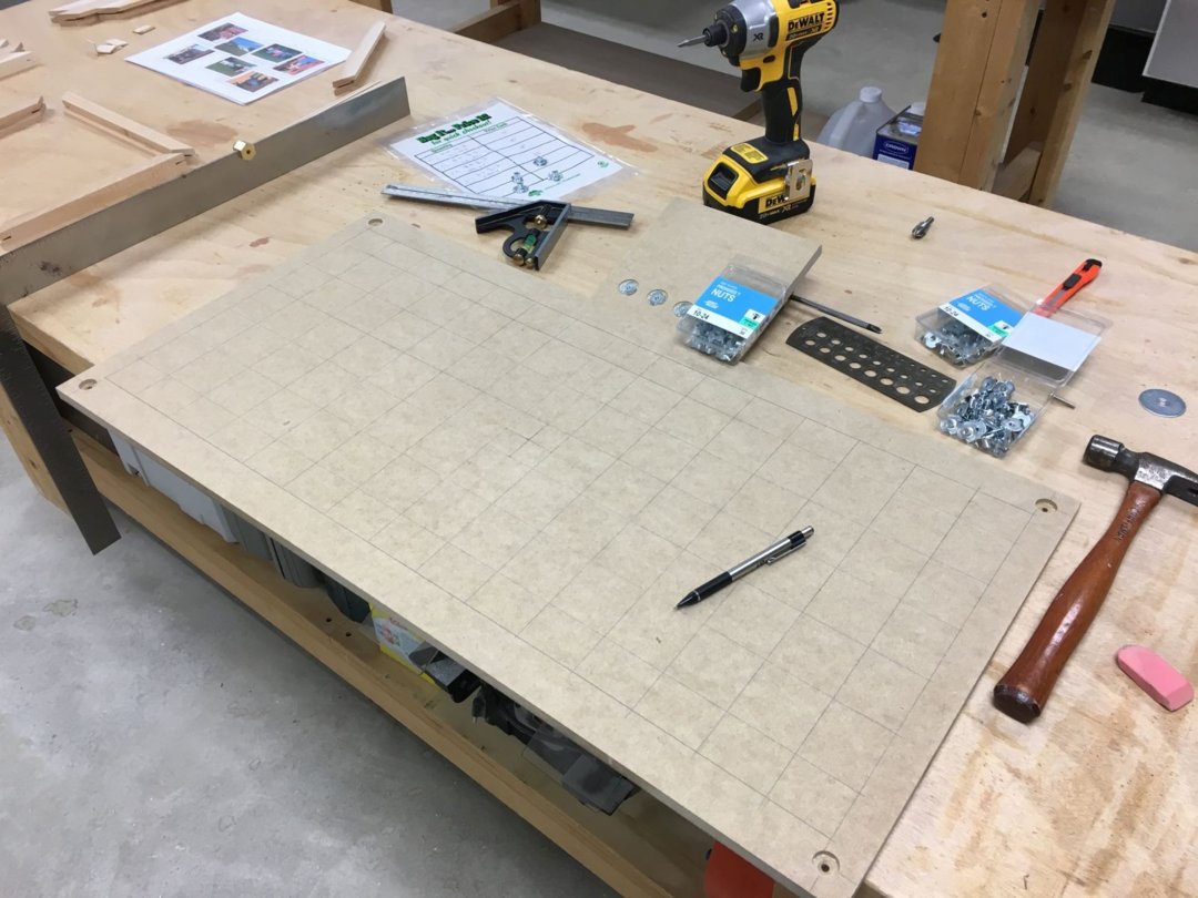
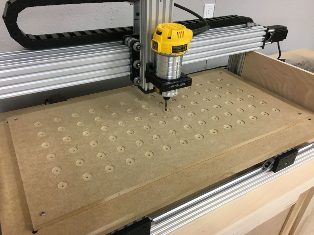
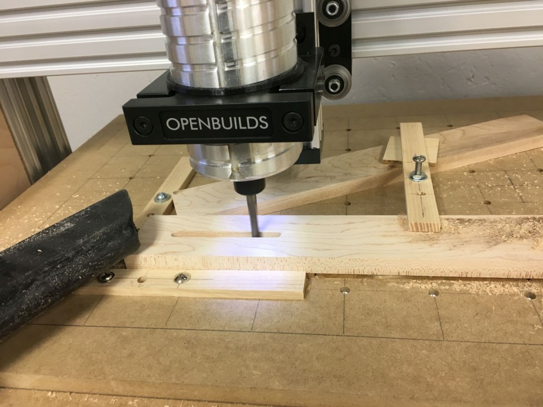
Spoilboard Hold Down System
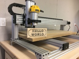
In my very first "Hello World" run (shown in the video under Early Action Videos), I used blue painter's tape to hold the workpiece down to my spoilboard ... and I knew that wasn't the method I wanted to use going forward. I decided on a light duty clamping system, similar to those used on industrial milling machines.
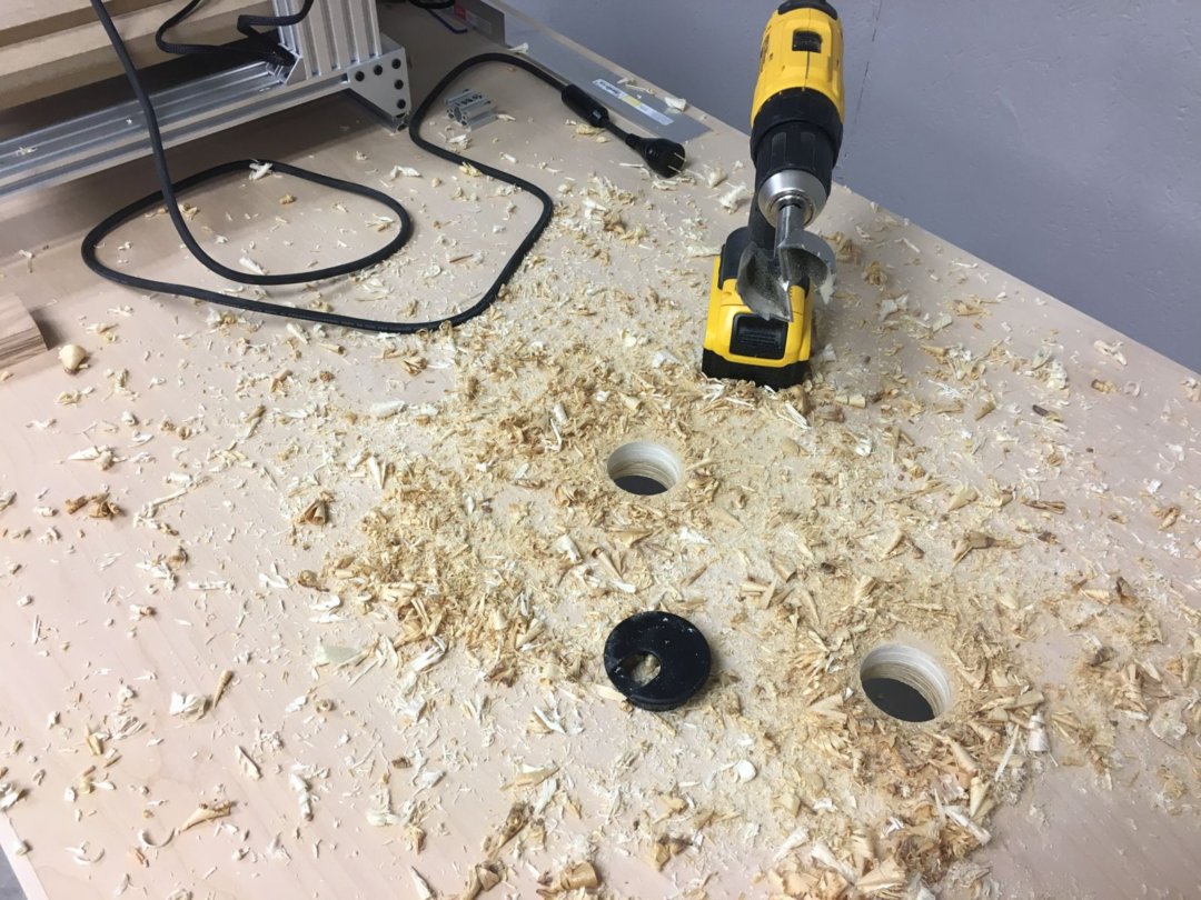
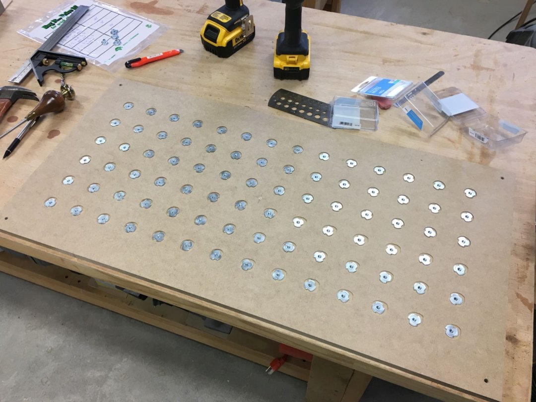
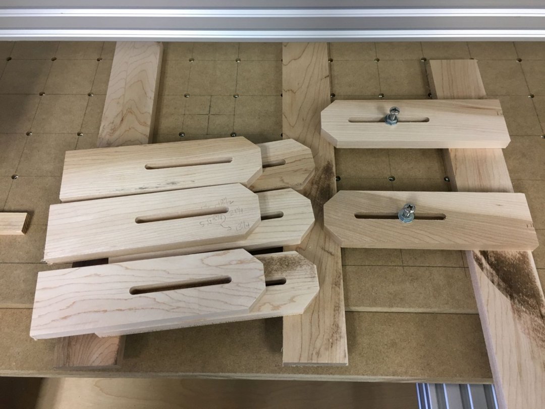
I drilled holes in my spoilboard on 2 inch centers, counterbored the undersides, and installed a bunch of 10-24 tee nuts. Once this was completed, I machined some clamps from scrap maple strips, added an assortment of 10-24 stainless steel fasteners, and had myself a solid, flexible clamping system, as illustrated below.
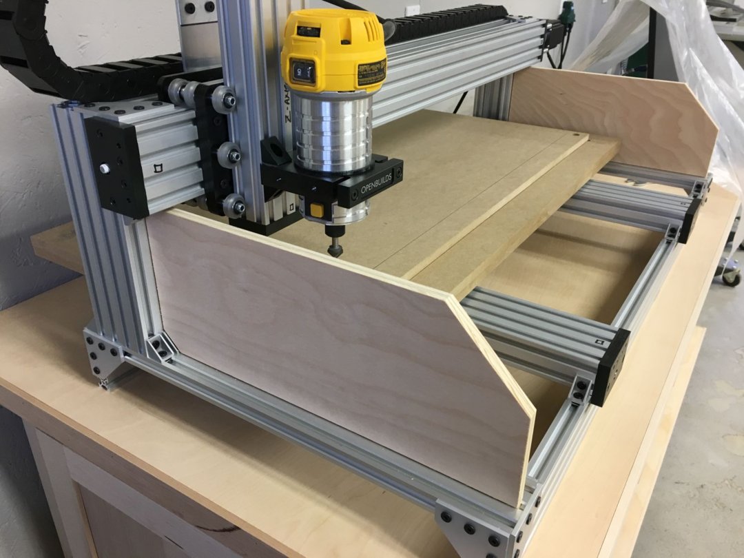
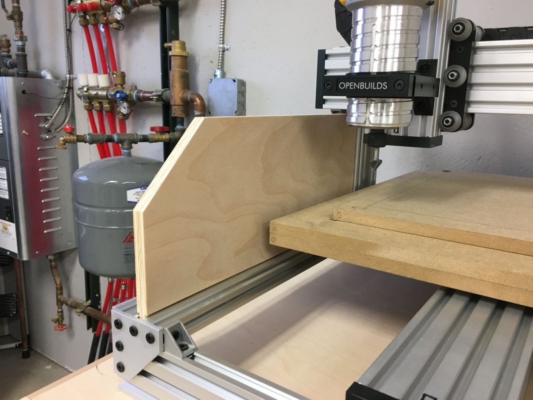
Removable Plywood Side Shields
I mentioned earlier that the chips and dust were flying everywhere on my first few runs. I looked at the OpenBuilds optional design for polycarbonate side shields, which were attached with some of their standard connection hardware.
I decided to do something similar, only with a few scraps of 1/2 inch plywood, and make them removable, for easier cleanup. Using my tablesaw, I formed tongues on the bottom and back edges of the plywood side shields, making them a width that was a nice slip fit into the channels on the V-Slot extrusions. Other than not having any transparent plywood on hand, they are working well. Here are a few pictures to illustrate.
Early Action Videos
Here is a short video of my very first "Hello World" run on my OpenBuilds C-Beam Machine XLarge. I used a chamfering bit that I had on hand, as this was before I acquired any proper CNC router bits.
And finally, here is another short video of one of the holiday gifts I made for my longtime friend, Russ. The vee carving is being done with a 60 degree vee bit on a bamboo cutting board.
20180228 Update: Increased Z-Axis Capacity
The original design of the C-Beam Machine XLarge provides for only about 1 1/2 inches of travel in the Z direction, and I've found this to be somewhat insufficient.
I've replaced the 250 mm C-Beam vertical frame members with 350 mm extrusions, raising the fixed X-Z gantry up about 4 inches. I chose this amount for two reasons:
I now have ~3 1/2 inches of travel in the Z direction. After running a few jobs at the lower reach of the increased Z-axis travel, my initial observations indicate that no additional flexure has resulted from this modification.
- I thought / felt / hoped this additional height would not add too much flex to the Z-axis.
- No modification to the existing Z-axis linear actuator was required to take advantage of (most) of this additional travel in the Z direction.
One of the great things about using OpenBuilds V-Slot and C-Beam extrusions is that this modification is completely reversible, with about an hour's worth of time needed. So far, I have no reason to go back, though!
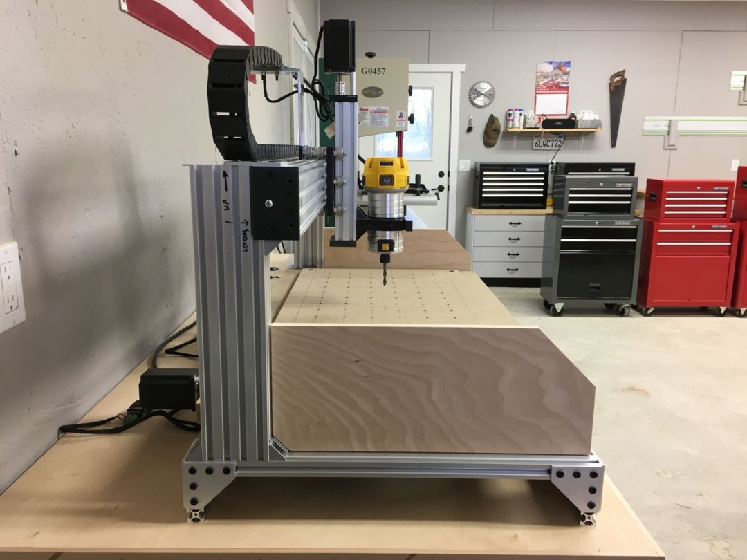
Prior to installation, here's a comparison of the 250 mm vertical member (on the left) and the 350 mm vertical member (on the right).
I only had to disconnect my cable carrier from the frame before I removed the X / Z axes assembly intact. This made for a quick reassembly after I swapped out the vertical members.
Here's a detail of the frame corner with one of the original vertical members removed.
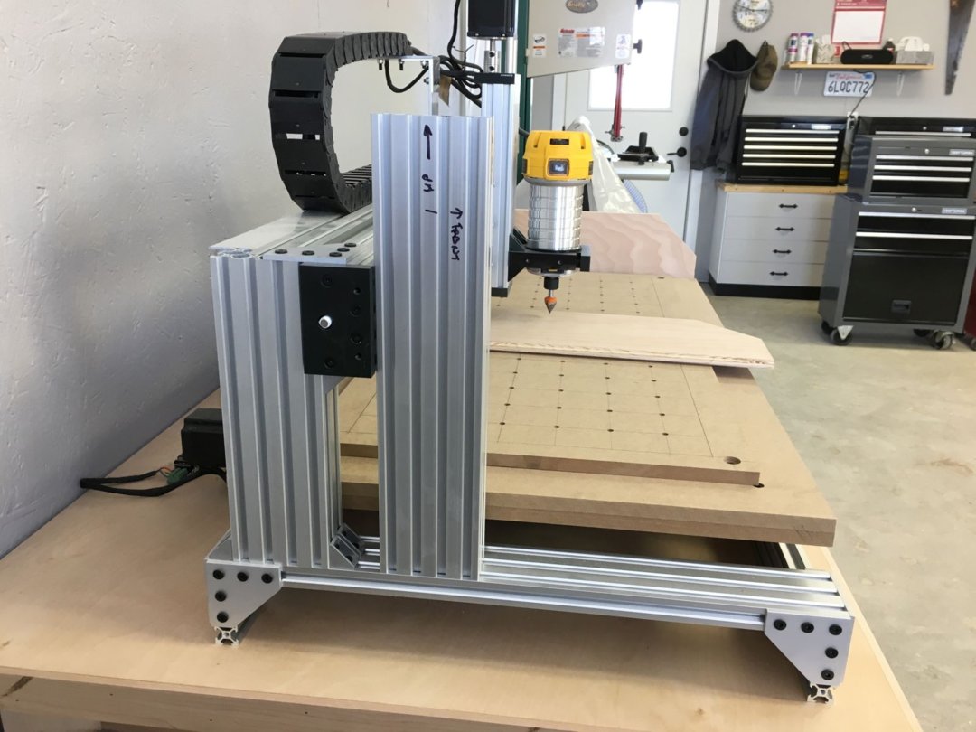
Here's a side view showing the increased Z-axis capacity of my C-Beam Machine XLarge. One miscalculation on my part was not allowing for the Z-axis Lead Screw Block, which resulted in about an inch less increase in Z-axis than I had anticipated.
This front view also shows that I was able to lower the router motor in its mount by about an inch, giving me easier access to the spindle lock button, and exposed more of the router body, which I may need if (when) I get around to mounting a vacuum dust shoe!
Planned Future Enhancements
Now that I've increased the Z-axis capacity on my C-Beam Machine XLarge, at some undetermined point in the future (most likely when I get tired of vacuuming everything after every project), I also plan to add a vacuum dust shoe.
I'm thinking about trying a couple of adjustable air jets blowing chips toward a vacuum "scoop" rather than a traditional bristle-type dust shoe that hides the business end of the bit contacting the workpiece. If you have thoughts, or any experience with an approach like this, I'd love to hear about them!
All the best,
Rob
Rob's C-Beam Machine XLarge
Build in 'X/Y Table Style CNC Mill' published by Rob Mahan, Feb 28, 2018.
This is my first CNC router build, so I started with the OpenBuilds C-Beam Machine XLarge mechanical bundle, including four high torque stepper motors. I took my time with the mechanical build, sought and found some great help for my control system, and designed and built a custom cabinet to house everything.
-
-
Build Author Rob Mahan, Find all builds by Rob Mahan
-
- Loading...
-
Build Details
- Build License:
-
- CC - Attribution - CC BY
Reason for this Build
I am a long time straight line woodworker and furniture builder, inspired by my Pop, who built the house I grew up in with not much more than a hammer and a table saw. I built this CNC router to learn new skills, to enhance the capabilities of my workshop, and to be able to incorporate more artistic work into my projects. -
Parts list
Qty Part Name Part Link Comments 1 OpenBuilds C-Beam Machine XLarge Mechanical Bundle http://openbuildspartstore.com/openbuilds-c-beam-machine-... Link Illustrated assembly instructions also available at this link. 4 Nema 23 Stepper Motors - High Torque http://openbuildspartstore.com/openbuilds-c-beam-machine-... Link Included as an option with the mechanical bundle. 1 DeWalt 1-1/4 HP Variable Speed Compact Router https://www.dewalt.com/products/power-tools/routers-plane... Link A shim was required to fit this router to the OpenBuilds router mount. 1 Gecko G540 Motion Control Package http://stores.ebay.com/eDealers-Direct Link This package from eDealers Direct on eBay, includes the following items: 1 G540 Rev8 Digital Stepper 4 -Axis Driver System Link 1 Aluminum Enclosure (EMI Dipped) Link 1 48 VDC 12.5 A Power Supply Link 1 Integrated Cooling System w/ Fan and Heat Sink Link 1 G540 DIY Labeling Kit Link 4 DB9 20 AWG 13 foot Motor Cables Link Male/Female Connectors 4 DB9 Pro-Solderless Connectors Link 4 Current Resistors Link Custom matched to my NEMA 23 motors 1 UC-100 USB Motion Controller Link This interface allows the use of Mach3 with a non-parallel port PC 1 Mach3 License Link 0 Gecko G540 Motion Control Package - End of Listing Link 1 IGUS e-chain® Series 14 https://www.igus.com/iPro/iPro_01_0003_0001_USen.htm?ArtN... Link Part No. 14-3-048-0 Length 1159 mm 0 IGUS Mounting bracket, full set with tiewrap clamp Link Part No. 114-3-12PZ -
Attached Files: