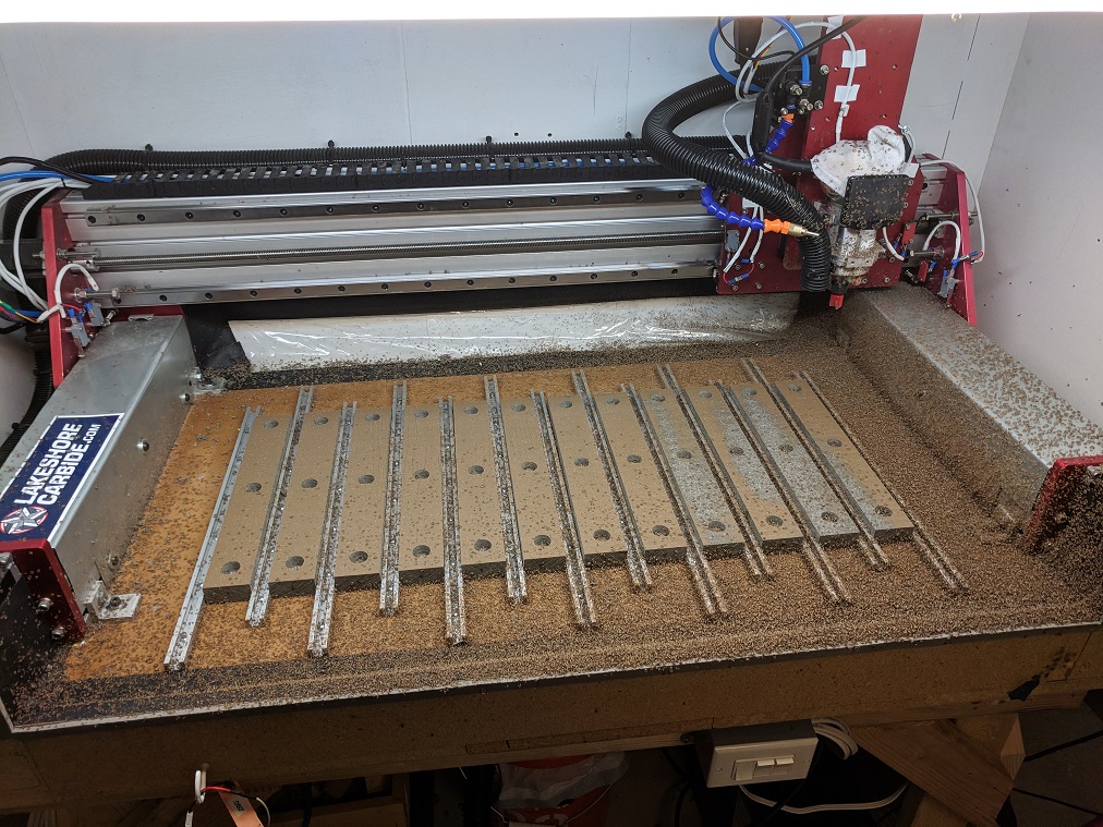
Current status:
Operational, chips are flying! This image is just after facing the bed.
--------------------------------------------------------------------
Build History:
For a while now I've been wishing my Shapeoko 2 was more rigid. I've cut aluminum with it before, but it was not an experience that inspired confidence. The bit chattered a lot, and I had to stand there with WD40 to keep it lubricated. So the time has come to upgrade it. Significantly.
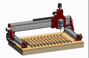
For reference, here is a model of my current machine, which is a 1200x500 Shapeoko 2, which uses Makerslide, 6mm GT2 belts, v-wheels, and Nema17 motors. (I should also note it uses a Makita router and aluminum spindle mounts)

Early version of the upgrade design using non-captive stepper motors on leadscrew:

For a while I thought about sticking with a belt design, using 9mm wide belts. Gantry was going to be 2x4 rectangular aluminum tube, and would have to be machined at a real shop.

Switched to 3x6 extrusion for the X-axis gantry and 3x3 for the Y axis, with a pre-made Z slider from CNCnewbie.

Current design. Updated the Z axis to my own design using long-version profile linear bearings.

At first this was going to be just a gantry upgrade, but it quickly turned into much more as I thought about each piece. As you can see, this is turning out to be more of a complete rebuild, rather than an "upgrade." I'm not even sure any of the bolts will be original parts when I'm done.
Goal #1: Keep the same overall size
My current machine is 1200mm in X, and 500mm in Y. I know this is backwards from a stiffness point of view, but the long gantry makes it really easy to work with. I don't have to reach over the side rails. Plus, I just finished building an enclosure, so it has to fit inside that.
Goal #2: Eliminate the sources of flex as much as practical. Be able to cut aluminum with ease. Stretch goal: Be able to cut steel on occasion.
Most of the flex I am seeing manifests itself as twist around the X axis, but there are still several sources that contribute to this (in order of significance):
Goal #3: Eliminate sources of inaccuracy and calibration headaches.
- Torsional rigidity of the extrusion itself: At first I was just going to just buy the "wide makerslide" to replace the original double makerslide setup. But with a 1200mm gantry (longer than SO3 XL), I'm not confident that this will give me the stiffness I'm looking for since the SO3 uses a variation of 80x40 extrusion.
- Flex in the carriage: I can clearly see that the carriage is also flexing relative to the extrusion. There are things I could do to stiffen this up, such as mounting each front and back pair of wheels on a single, longer bolt. But there is still a significant amount of flex in the delrin wheels and bearings. Steel wheels would be more rigid, but those cant ride on aluminum makerslide). I could try Openbuilds' solid wheels, but they will never be as rigid as other methods, and it still has the annoyance of running over debris that falls on the extrusion, causing the cutter to walk. So I decided to ditch all that and go with what the big boys use, which is Hiwin-style linear bearings.
- Flex in the Z-axis: Here we have the same v-wheel setup, with the same problems I just mentioned. Let's get rid of that. CNC4Newbie.com sells Z-sliders that use LM12 linear bearings on round rod. Bonus, it includes ACME rod! It comes with a hole pattern that will fit an X-carve, which will fit an SO2. With a slightly different hole pattern (free of charge), it will fit my Makita mounts. Haven't quite decided if this is the unit I want yet. He sells some other units which look promising also.
The main culprit here is the belts. My machine lives in the garage where temperature fluctuations happen a lot. Belts stretch and the controller needs to be calibrated to the specific belt tension. The belt is the thing reacting the tool forces and will stretch against the load, and cutting aluminum well will require something better, more accurate, and free of stretch. And, aside from cost, belts just don't seem like a good idea on a CNC machine. For a 3D printer they are great, but a CNC needs something better. Whenever someone asks me about my Shapeoko, I describe it as a "CNC designed by people who usually build 3D printers."
▲ Intro
------------------------------------------------------------------
▼ Build Updates
UPDATE 10-18-2017
I ran some FEM analyses using Creo Simulate on a few different extrusion sizes and compared to the double makerslide.
Deflection of 1200mm double makerslide (bolted together) with a 30 in-lb moment applied in the middle. If I do the trigonometry to get the deflection at the cutter tip, I come up with .006"

Here is Misumi's "rigid-type" 80x80mm with the same moment. Deflection at the cutter tip would be reduced to less than .001".

And here is Misumi's 100x50, which is not quite as good as the 80x80:

To be clear, on my current machine I am seeing about .015" of deflection at the endmill bit, when I apply 5 pounds on it, at about 6 inches away from the rail center (5lbs x 6in = 30 in-lbs). The fact that this is more than the .006" calculated by the FEM means there is significant deflection in areas other than the beam twisting, such as V-wheels, carriage, belts, etc. I already knew that, which is why I am replacing the V wheels with linear guide.

UPDATE 11/7/2017
Major Update & redesign
Current design:
- 3"x6" T-slot extrusion for the X (gantry), 48" long (automation4less). It's 28 lbs!
- 3"x3" T-slot extrusion for the Y rails, 20" long (automation4less)
- 1/2" thick aluminum end-plates all around, sourced from a local metals supplier.
- 3/8-8, 4-start lead screw on the Y axis (dual driven) (source TBD)
- 1/2-10, 5 start lead screw on the X axis (source TBD)
- Motors will probably be 269 oz Nema23. (source TBD)
- Linear rails are BLH 20mm rail. X guides are 1155mm, Y guides are 506 (2mm short of 508, which is 20") (automation-overstock).
- Z axis will be a purchased unit, probably from cncnewbie
And now for pictures.
- Approximate cutting area is now 34" in X and 13" in Y. Bottom edge of the carriage plate is 4.1" from the spoilboard. Haven't quite decided if I want to keep that or go slightly taller to accommodate thicker materials.
Leadscrews are held using a fixed-supported arrangement, with the fixed portion being the end opposite the motor with a couple of pillow blocks from servocity. The end closest to the motor is just supported by the motor itself with a flexible coupler. I suspect the bearings that come with the pillow blocks are radial contact. If I get whipping I may switch them out for angular contact.
Limit/homing switches and hardstops on the X axis are independently adjustable.

Cross-section thru bearing support:

The leadnut block on the gantry plates is a 2-inch piece of 1x3 extrusion, with an AB nut from dumpstercnc. Limit/homing switch position is adjustable. Hardstop is just when the linear bearing runs into the Y end-plates, which have a cutout to accommodate the grease fitting.


All end-plates are intentionally simple, so that I can just peck the hole-centers and cut a shallow part outline on my current machine, then cut out the part on my table saw or chop saw, and drill all the holes in my drill press.
(view from the rear of the machine with X rail hidden). X axis AB leadnut is from cncrouterparts.

side view.

Update 11/14/2017: Build Phase Started
Gantry Plates
Now for the exciting part. Hardware is starting to arrive.
Setting up the tool paths. Note that because my current machine lacks stiffness, I'm just pecking the hole-centers with a V bit, and cutting out a .050" deep outline of the parts (using trochoidal paths, which might be unnecessary). The final part outline is to be final-cut using a table saw and miter saw with a metal-cutting blade, and corners filed by hand. I did have to mill out the larger holes for the stepper motor and bearing block. Using a 1/4" 3-flute end mill and trochoidal pockets, it wasn't too bad, although I did notice that the large hole isn't 100% round so it may need some hand-filing if the motor doesn't fit. Used 20 ipm feed, 10,000 rpm, .0625" depth of cut with a 1-degree spiral entry.


One end-plate almost done. Here I'm tapping the motor-mount holes to accept 10-24 helicoils later.

Fit check with the gantry rail.

I ordered some anodizing supplies. Plan is to red-anodize all of the end-plates. Note: if someone is planning to reproduce something like my build, do NOT install the helicoils until AFTER anodize is complete. The steel helicoil will dissolve in the acid.
Update 11/18/2017
X and Y extrusions from automation4less.com, and linear guides & bearings have arrived from automation-overstock.com. They appear to be very good quality. One minor annoyance is that the spec posted on the website says the bearings have M6 threaded holes, when in-fact they have M5 holes. (so don't use that spec!) I had been emailing back and forth asking about the long version of these bearings, which are available but not posted, and they sent me the spec sheet for ALL sizes (attached here at the bottom). that is when I noticed that parts of it didn't match the other spec and checked the bearings I received. When I brought this to their attention, I got radio-silence. So if you order these BLH bearings from them, beware! Unfortunately I had already drilled the holes in my gantry plates for M6 screws, so there is more slop than I had intended. (It's a 5mm/.197" screw in a 6.75mm/.266" hole -- pretty loose. Anyway, I bought some tube so I can make "bushings" with it, which will fit over the screws before inserting them, and take up some of the slop. I was sorta hoping that by bringing this discrepancy to their attention that they might offer me a discount on my next order. If & when I get a response from them I'll update here.

Ends of extrusions tapped and helicoils installed.


Bearing arrangement re-design, with BEEFIER bearings. I couldn't find any bearings already mounted in flange blocks that didn't cause problems (most are just way too big), so I will just have to make my own.

Update 12/4/2017
Kinda slow progress as I am only really able to work on this when my toddler daughter is sleeping.
Successfully anodized some of the plates! The parts are a brilliant red


Basically my process is:
1. Sand parts to get rid of scratches etc. I went up to 800 grit.
2. Degrease parts. I used brake parts cleaner in a spray can.
3. Wash parts. I used simple green and a scrub brush. Parts need to be "surgically clean". Any oils will interfere. Don't touch parts with bare hands beyond this point.
4. Anodizing: Sulfuric Acid solution needs to be about 15% concentration. Battery acid from the auto parts store is roughly 35% sulfuric acid, so diluting 50-50 with distilled water will get close. I bought a battery hydrometer to check the specific gravity to verify, because according to the MSDS for the battery acid, the tolerance on the 35% is quite large, and I expect some of the water to evaporate over time. (Remember add acid to water, and wear gloves& goggles). For cathodes I have 2 titanium plates (10cm square) suspended on the sides of the tank using hooks made from bent aluminum rod. (Ti is supposed to last longer than Al). To suspend the part I also used titanium rod. Hook up a battery charger, + to the part and - to the cathodes. For current, you need to calculate the surface area of the part. The rule is 720 amp minutes per square foot will produce .001" of oxide. In addition it should be at least 12 amps per square foot -- I'm using about 16 a/sf. For the 2 larger parts (165 sq. in. each) I ended up doing about 20 amps for 30 minutes with "motor drive" mode on my smart charger. Voltage was about 14v but to you should try to use constant current and let to voltage do what it needs to. Cathodes will bubble a lot. I did it in the garage with the door open and a fan blowing because it produces hydrogen. (Actually on the first attempt, the wire I used to hang the part was too thin, and started glowing. Probably not a good thing with explosive gases being produced!)
5. Rinse part. I rinsed in tap water but then spray with distilled water to keep from affecting the PH of the dye bath.
6. Dye. Mix up dye per directions with distilled water. I used actual anodizing dye but you can also use Rit, etc. (I read that Rit will fade I'm sunlight). Dunk the part and leave in there for up to 15 minutes. I did about 10 min and didn't worry about heating it up. You can heat it (but only a little, like 100F) which will reduce the time.
7. Seal. Boil the part for at least 10 minutes. I'm still experimenting with the boiling time. I ended up doing about 20-30 minutes. Some of the dye will leach out at first, so make sure the color starts out slightly darker than you want. Steaming instead of boiling will apparently reduce that, but can also result in splotches.
The beefier bearings arrived, and I was able to press them into the blocks I made using a vise.

Update 8/19/2018
After a LONG hiatus, I've picked this up again. Back in December/January, I got to the point of needing to order motors, drivers, motion control board etc. and couldn't decide which way to go, so nothing happened.
Well, now I got the motors at least. They are Nema 23, 269 oz-in motors (p/n 23HS30-2804S from StepperOnline).
As for other electronics, I'm thinking of going with an Ethernet SmoothStepper, and 4x DM524T drivers (what's the difference between that and DQ542MA that OpenBuilds sells? no clue) Still need to decide on a breakout board, power supply, and get a copy of Mach3.)
It's now 95% assembled. Needs limit switches and to bolt it down to the base. I also need to order some drag chain. This thing is sooo much more rigid than the SO2.

Sitting in my very messy garage next to the old SO2. Need to bolt it down to the base. The base isn't great, but I suppose it will work for now. Would be nice to have a piece of MIC-6 or a granite slab, but that's another $400+ I don't want to spend right now.

Update 9/18/2018
Machine is mechanically complete, and placed back into the enclosure I built for my original SO2. Got all limit switches installed and wiring/connectors on the machine side completed. Most of the electronics (with a temporary 12v power supply) are mounted to a piece of MDF and wired up. All the magic smoke stayed in! Got my copy of Mach4 running and was able to calibrate the motors and get the axes moving correctly. The Y axis is binding a little, so it needs some adjustment. The real 48v power supply, when it arrives, should also give the motors more torque than they currently have with the temporary 12v setup.
I ordered a PC case and will put all the electronics in it.


Update 10/4/2018
A lot has happened !
I made some Y-axis rail covers from sheet steel. When I first put them on, they resonated quite badly when the machine was moving around. I tried gluing some foam to the underside but it didn't help much. Interestingly, I had been using a temporary 12v power supply until the 48v arrived, but after connecting the drivers to the 48v power supply, most of that resonance is now gone and the machine is much quieter and stronger.

I finished the electronics enclosure. Fittingly, the PC case I got is called "Carbide" Spec-01 from Corsair. I will probably add 1 more relay board and outlet for control of the air-blast / mist-coolant pump. This is a mid-tower case, and I almost wish I had gone with a full tower for more room to work inside. There is even a SEPIC regulator so I can dial-in the fan speed to anything between 5 and 30v, although heat buildup seems to be negligible. I also put a piece of plexiglass covering the fan ports on the top side, so that any chips can't fall into the case.


Next up was squaring the gantry. Since each Y rail has its own motor and limit switch, I needed to adjust the homing-switch stops such that when homing the machine, the X-axis gantry ends up exactly perpendicular to the Y rails. For this I used Fusion360 to generate a pocket cut that my machinist square would fit in. I had to repeat this cut a and adjust the stops a few times. Particleboard probably isn't the best material to do this in, so I may repeat it yet again later.

Next was the real test: attempting to cut aluminum. This was a facing operation followed by a deeper slotting pass that was going to transition to adaptive clearing, but I didnt quite make it to that last part. It didn't go as well as I had hoped but brought to light some issues I needed to address. You can see where things went bad on the right side of the part:

1. I noticed that after the facing op, there were some tiny walls of material remaining between passes. Turned out that my X-axis leadscrew nuts were not tightly clamping the bearings and allowed the leadscrew to shift about .010 to .020"
2. Whenever the cutter started to load up, I was getting an error in Mach: "clearing a spurious limit switch latch event." This was caused by noise on the 110vAC wires powering the spindle transferring to the 5vDC signal lines, even though my signal lines were shielded and grounded, and I had programmed in some noise filtering in Mach. This meant I needed to physically separate the high voltage AC lines from the low voltage DC lines as much as possible. I shifted the wires in my drag-chain so that all the signals were on one side, and the AC power was on the other. This is only about an inch of separation but it seems to have solved the problem. I haven't tried higher spindle speeds yet, so hopefully this issue doesn't come up again.
3. I also had a problem with the workpiece shifting as I cut it, even though my clamps were tight. I think there are several things that contributed to this. I think the cutter I was using (1/4" 3 flute carbide uncoated) had a chipped tooth, and is not a "variable flute" cutter. It's also a relatively long, 3" cutter. My clamps are made out of wood and can only develop so much clamping force. These factors caused vibration and excessive cutting forces that were enough to push the workpiece. To solve this I've ordered ZrN coated, variable flute cutters from Lakeshore, along with a TAS roughing bit. I also plan to use the painter's tape and superglue hold down method next time.
4. There were also some shallower ridges between each pass. This is a spindle tramming issue and shows that the spindle slightly rotated about the Y axis. I may have to enlarge the thru-holes in the 2 aluminum spindle holders to gain enough adjustability to solve this.
I also ordered an aquarium pump and an air-blast / mist coolant nozzle.
The last few evenings I've spent working on the scripts & macros in Mach4 to get it to behave how I want regarding tool changes and having to manually set the spindle speed on the Makita router. Whenever Mach encounters an M6 tool change, the machine now moves the Z all the way up, and X/Y move to front and center, and there is a popup telling me which tool to change to, re-zero the Z axis, and hit cycle start to continue. Whenever it encounters an M3 command (turn on the spindle), it turns on the spindle and there is a popup telling me what RPM to set, and approximately what setting on the dial this should correspond to (for example, 15000 RPM = 2.35 on the dial), then hit cycle-start to continue.
Update 10/27/2018
Machine is fully operational!
I re-did the bed. I want to experiment with mist-coolant at some point. I know WD-40 "works", and will not cause MDF to swell, but most real coolants are water-based, and they would cause swelling problems. So I put 2 coats of epoxy on the base, doubled the number of T-tracks, and switched to composite decking-boards for the bed ("Trex" brand), which is mostly PVC. Since Trex does contain some wood fibers, it may still swell with moisture, but it is easy enough to change later.


I also spent a good bit of time tramming the spindle and squaring the Z rails to the bed -- neither of which are particularly easy adjustments to make and require partial disassembly and re-checking tram. So I will have to think about possible mods to make that easier.
Cutting my first real part in aluminum. I have been cutting dry, with the aquarium pump turned on. The aqarium pump helps to clear chips but I would like a stronger blast of air. My air compressor works much better but only has about 5 minutes worth of air, and when it charged back up, it's LOUD. Anyway, the part came out pretty good. Not perfect, I goofed it up in a couple places, but as I continue to learn, the parts will get better. This is so far beyond my old Shapeoko 2. I would say my goal of being able to cut aluminum "easily" has been achieved.


And here it is taking some real cuts. Your cutters will last longer if you can cut with more of the side of the tool, rather than just the tip. This is .250 in. deep cuts, .020 in. radial DOC, at 200 in/min with a 3-flute .250" TAS rougher from Lakeshore Carbide. 25k RPM.
RigidOko
Build in 'Cartesian Style CNC' published by SecretSpy711, Sep 3, 2019.
Heavily upgrading my 1200x500 Shapeoko 2... ...er, wait, scratch that... Building an all new machine, roughly the same size, that should be more rigid than a Shapeoko 3!
-
-
Build Author SecretSpy711, Find all builds by SecretSpy711
-
- Loading...
-
Build Details
- Build License:
-
- CC - Attribution Share Alike - CC BY SA
Reason for this Build
Because I want to cut aluminum and my SO2 is wimpy.Inspired by
Shapeoko 3, OX, CNCrouterparts -


