INTRODUCTION
This is my second build on here and I'm really excited to share it! I think I'll eventually delete the previous build unless people have an interest in the old files (let me know in the comments). The previous files were able to be 100% 3d printed, which was a great way to get into the game of CNC for me seems how I own a Prusa I3 mk2.5. Once the CNC router was built, it's then been slowly upgrading itself into what it is today, which is different in every way.
I'll be updating this with progress photos as I go. On the agenda for this build that I hope can be of some help to people just getting started:
- Custom rolling bench with lower storage (50% complete)
- Convert old dustbuster into a 5 gallon bucket vac.
- Why? Well, it was free, so why spend the 30 dollars on the bucket vac lids when I have a bucket and a vac for free.
- Make / buy an air blast system – Currently I’m using a fish tank pump. It gets chips out of ¼” pockets fine and that’s the deepest piece of aluminum I’ve cut.
- Upgrade existing belt driven mill to rack and pinion system (FINISHED!)
- Complete electronics enclosure
- Complete Custom Raspberry Pi based pendant controller running CNCjs for motion control.
- Build some sort of vacuum hold down system
- I’m thinking of making little vacuum pucks like Rockler sells rather than a full vacuum bed. I probably can’t afford a vacuum powerful enough to be useful for a full bed and Clamping is never an issue on bigger parts for me, it’s holding strategies on smaller or awkwardly shaped parts that I need a vacuum hold down for. I plan on these pucks being either in designated locations under the MDF or to have removable holes in the wasteboard that they can be seated into.
I haven't seen too many rack and pinion systems out there for home brew builds, and I know people are going to ask "why not ball or lead screw" but I promise I have my reasons! Speed, price, agility, adjustability, and again price, brought me to this conclusion. Also, in terms of going from the previous belt drive system to a rack and pinion, the upgrade wasn't incredibly painful to think about in terms of necessary modifications. A belt drive is essentially a crappy rack and pinion, in my opinion.
MACHINE BUILD/UPGRADE:
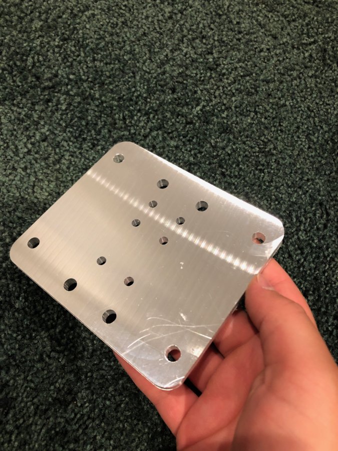
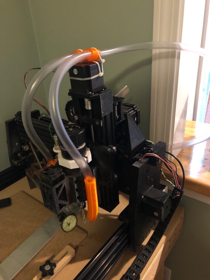
This is the first piece off the mill that's made out of aluminum. It's for the z Axis and it's only temporary. There was a lot of slop in the Z axis when milling aluminum so this was milled super slowly so that I could at least beef it up temporarily while I finish the rest of the parts.


The next step was milling out the gantry plates with the upgraded Z axis. The top wheels are on adjustable rollers so I just blocked the gantry up with the lower wheels pushed into the extrusion, and then pushed down on the top rollers so that they'd slide down and apply even pressure. It seems to be working fine without any play. The stepper motor can also slide up and down so that it will mesh with the rack. The rack is yet to be installed as I ran out of m5x12 countersunk screws and T nuts.. I didn't even consider checking as I always have so many of these...
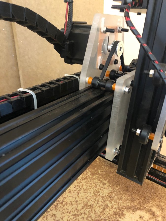
These are test parts milled out of acrylic for now. For the moment, I'm going to leave the X axis as belt driven and only upgrade the Y axis to have a rack and pinion system. I'm hitting numbers within 2 thou in the x axis (short axis) which is fine for the time being, but the extra length of the belts in the Y axis is leading to some pretty unacceptable slop and is as much as 1mm off at times.. Fine for woodworking projects in my opinion but unacceptable for when I need to make functional parts. The X axis did get a slight upgrade though, as it is now double belted to help counteract some of the stretch in the belt.


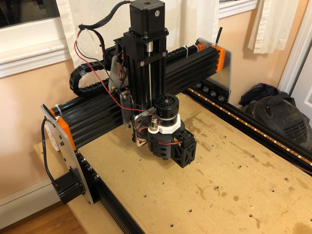
I'm super excited to say that the machine portion of this build is complete, and therefore I'm marking the build as complete. I will continue to update it as I upgrade and create new things for the mill but for now it's time to make some gifts for the holidays! The rack and pinion is mounted with 3d printed hold downs that also have industrial grade double sided tape. This is how our ShopBot at school does it so if it's good enough for a 40,000 dollar router table it's good enough for my sub 1,000 dollar router table.
I only had time to do a quick test in wood today before starting to make gifts, which really don't need to be that accurate but after tuning in my steps per mm i was hitting .0003" which is good enough for me for once I start making more mechanical parts! If anyone has questions about the build or the rack and pinion system let me know and I'll try to answer in the comments. I'm also still a graduate student, but when I have some time after graduating in April I would love to be able to put together a parts list and make the files available for everyone as this mill has far exceeded my expectations in terms of speed, accuracy, and rigidity. I'm currently cutting with an 1/8" cutter at about 120IPM with 1x depth of cut and it seems like the cutter will be the victim of my slow spindle long before the machine's linear motion can't handle it.
PENDANT BUILD:

Test cut out of foam for the pendant. It will feature a key switch, E stop, touch screen, and custom mapped jogging controls. That's the goal at least. There's also switches that have been wired up to run lights, a vacuum, and an air blaster.
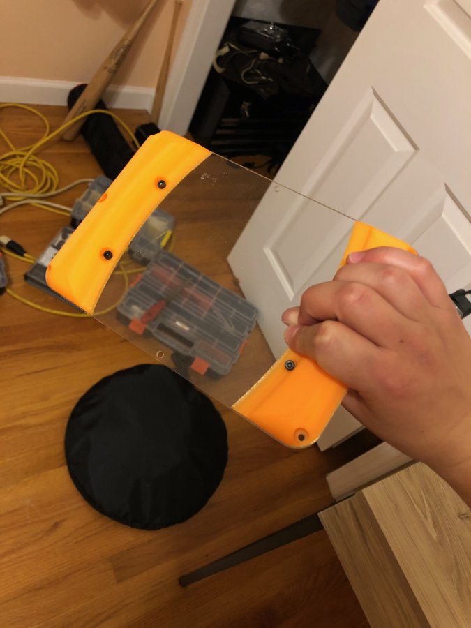
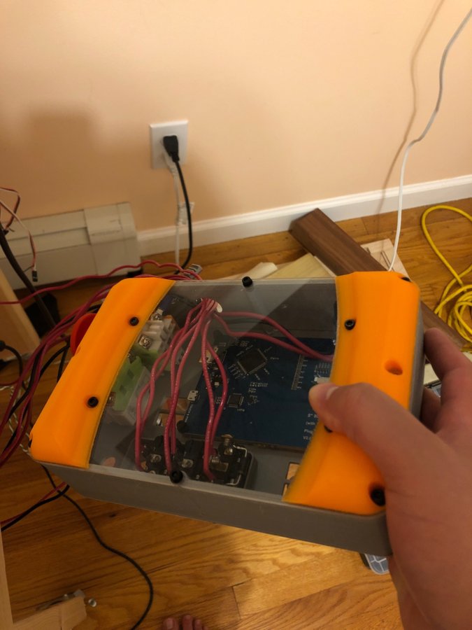
The plexi backing was milled just because I've never found touching 120VAC to be particularly fun (or safe). Once I finish the final design I might do something differently, but honestly if I threw some lights in there and worked on my cable management it might be really cool.
TABLE BUILD:
The table hasn’t been well documented as it’s a really simple build. It’s just some 2x4’s and MDF slapped together to make a lower bench for the vacuum, air blast, vacuum pump, etc and a table top for the mill to sit on. There may be a few accessory features I’ll add to the bench including a built in power strip for powering auxiliary tools, a home for my z plate and a side mounted fire extinguisher.
VACUUM / AIR BLAST SYSTEM:
This will be updated eventually. Right now I’m just using a cheap fish tank pump to blow chips out of slots, or as mentioned below, with the output of my shop vac.
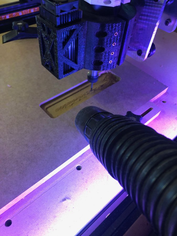
This is a pretty rough image of tramming in the spindle. Most importantly in the shot is the dust extraction that's temporarily been used as a blower as well for aluminum (just swapping the input on shop vac to the exhaust)... I know it's not the most efficient way of sucking chips up and maybe some day I'll have a dust shoe. But it does a pretty decent job at keeping things clean and it also allows for easy video as well by just having two hoses come in from the side and meet back up up top.
ELECTRONICS ENCLOSURE:
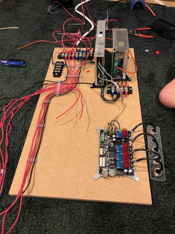
In this image are the rough locations for the PSU's and the smoothieboard. There actually needs to be one more power supply (12v) mounted in here for the laser. I left a lot of room for when I decided a 500 watt spindle just doesn't cut it anymore and I'll buy a proper VFD.
Another shot of milling out part of the electronics encloser. If you look and are horrified of the fact that I have the laser mounted to the spindle while it's running, fear not, I printed dust covers that protect the lens and other open areas, just pop them off and the laser is good to go. I also haven't been able to get the laser properly working on that, but more on that later... Probably not until I graduate from college next spring, I just don't have time to think about it and it's not super important to my work.
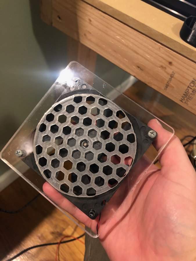
Custom fan case milled for the enclosure. It looks a little crappy because for some reason the stepper drivers on the Panucatt Azteeg x5 gt are super finicky.. In my case my steppers get permanently bricked if I plug it in ABAB instead of AABB and power it on. Well I didn't realize I had plugged it in incorrect so my poor Y axis was limping along with just a single stepper driver. Once I restored it to AABB, the driver refuses to function normally. If someone knows how to fix this please let me know... It seems like something that shouldn't brick the driver but its happened twice now (and funny enough the only two times I've plugged them in like that so it’s definitely the cause of the bricking) and then I have to buy new ones. I've done this on other projects with arduinos and pololu stepper drivers and nothing goes wrong if I just fix it later so that it's AABB. I've held on to the bricked drivers for now because I feel like there must be some way to get them going again. They just make a horrible noise now and vibrate the stepper motor back and forth a couple degrees.
VACUUM TABLE:
Not sure when I’ll get around to this. Maybe next year.
I think that's it for now! I'll be sure to be updating this as frequently as I can and I should have the racks installed this weekend to get some projects done before the holidays!
Rack and Pinion Cartesian Mill
Build in 'Cartesian Style CNC' published by Joe F, Mar 30, 2020.
This is a rework of a previous build I did on here, a mostly printed cartesian CNC. Initially intended to just be an update to that, but so many things changed including the linear motion and every single part has been modified significantly that I felt as though it deserved a whole new build.
-
-
Build Author Joe F, Find all builds by Joe F
-
- Loading...
