
Back in 2016 the primary objective of this build was to produce the cheapest possible laser etcher for someone with moderate production capability. It became clear that the solutions to that challenge weren't in line with what I was really interested in, process-wise, and so the project scope morphed over the last year or so into what it finally became as work started in late December.
As any of you who've been around for a while, I'm apparently constitutionally incapable of just, like... Making a normal thing. So this build is probably about what you'd expect.
While unlikely that many on Openbuilds would really need any of it, I did an introductory first installment in the video series:
The first half quickly goes over the components typical to builds like this, and the second half (from 12:22) goes over the three main goals of the project; 1) no bed, for portability and flexibility; 2) floating head- no z rails sticking down; and 3) substantial z-axis range for both cutting and etching as well as slicing in both.
It doesn't yet use a built-in power supply; 12-24V for the steppers, ~5V current-regulated for the laser, and 5V <500mA for the optical limits are all supplied by a Tekpower TP-3003D-3 bench power supply, which hopefully I won't need to use whilst cutting something any time soon! Likely I'll simply adapt an ATX PSU I have lying around in future, run the steppers at 12V and do a couple of regulation breakouts for the others.
Arduino running grbl and the motor shield logic are powered over USB, since I need to interface it with bCNC anyway!
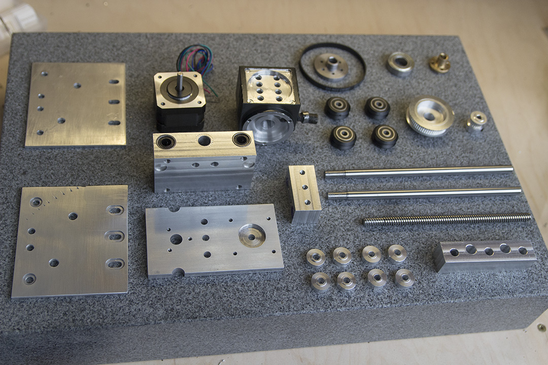
A comprehensive list of all parts and their provenances can be found in the Parts List.
I'm going with a 18x18 inch capacity class, since it's generally unlikely I'll be cutting anything larger than a sheet of paper, due to the low speed inherent to diode cutters (the low power requires both slower cutting and frequently multiple depth passes at those slow speeds... It's a steep curve on material limits). Also I'm trying to limit my use of V-Slot to the three pieces I already have (1x1500mm, 2x1000mm), and maintaining gantry rigidity with the 2040 size V-Slot all three pieces are.
The laser is a Nichia NDB7875 445nm diode; rated up to 1.7A continuous with passive cooling, 2.1A continuous with active cooling, for around 2.3 max Watts of optical power. I got it pre-housed in copper with a "G2" lens from DTR Lasers.
I was originally going to go for the 405nm 900mW BDR-209 diode, because the shorter wavelength (and likely less-rectangular output as it's single mode) focuses to a smaller spot and apparently actually produces a higher radiant energy density than the higher-power diodes, but I chickened out and got the one that I had already seen working on my intended materials and was a known quantity. The BDR-209 is something I want to experiment with in future; it's the same price as the NDB7875 but if it cuts better and with a smaller kerf, it would be logical to use instead.
Step 1: Head Design and Machining
The head itself has several specific requirements, which I go over here from 5:24 to 12:00, as well as testing the focus and looking at the CAD design in Fusion 360.
For the machining itself, this is a fairly substantial process which I look at here:
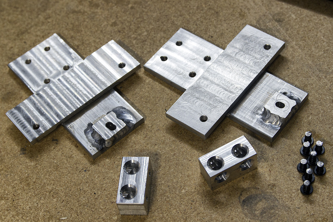
Step 2: The Z axis
The z axis required a lot of finagling, and after playing around in Fusion 360 and randomly measuring everything with calipers a lot, I finally got a design that functioned as I needed it to:
I didn't make a video explaining it, since I was making it up as I went along according to the guidelines in the second video, but the actual machining of it went as follows:
This was the trickiest part of the build; the simplest part, the plate spacer block, actually needed machining three times!
Not perfect... But I'm not complaining!
Step 3: The X-Y gantry frame
This is a pretty straightforward step, albeit with some mild tedium of building brackets and trimming screws...
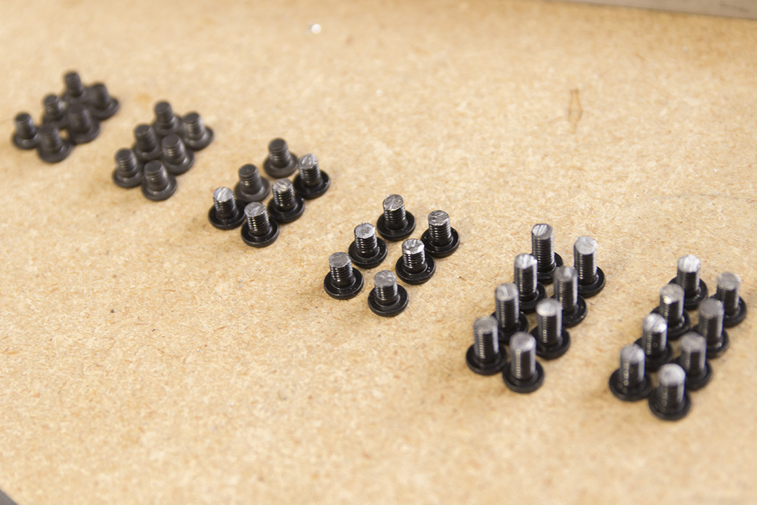
Then it went together quite quickly!
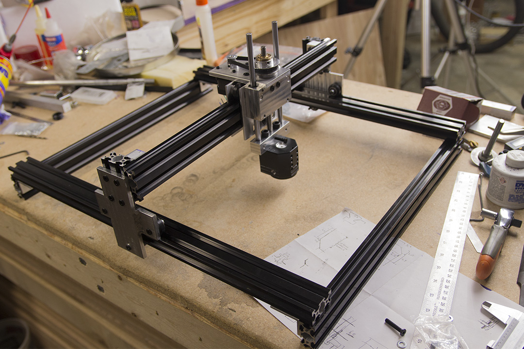

First major mistake of course occurred on the simplest part: the y-axis is two inches/50mm short, because the laser head bumps into the frame. I hadn't accounted for that since I never built beyond the gantry in Fusion 360. This puts the y travel at 15.25" instead of the 17-18" that I was aiming for in order to cover a full 11x17" sheet of paper. Whether I'm overly concerned enough about avoiding a matting margin on such a project to substantially redesign that side of the base frame, I'm dubious. I suspect 90% of projects will be smaller than 8x10" anyway.
Step 4: Flashing grbl to Arduino
Step 5: Testing and First Cuts
Cuts- paper, vinyl, spray paint on metal...
Step 6: Possible Next Steps
- Power supply for laser: adjustable constant current (op-amp?), zener input protection (needed for digital input?), schottky reverse voltage/ESD protection, high speed PWM control with transient suppression (big caps?), on-carriage location for minimum power lead length, other standard laser driver elements. (protection ideas from Optlasers page)
- fed from a cheap ATX PSU, adapted as necessary
- Permanent base station for below-bench storage (on (locking!) drawer slides) and operation when portability not required.
Portable Diode Laser Cutter
Build in 'Laser Cutter Builds' published by Rob Taylor, Jan 2, 2019.
Integrating custom machined components and off-the-shelf CNC components to create a portable diode laser etcher with air assist and reasonably substantial z-axis travel.
-
-
Build Author Rob Taylor, Find all builds by Rob Taylor
-
- Loading...
-
Build Details
- Build License:
-
- CC - Attribution Share Alike - CC BY SA
![[IMG]](proxy.php?image=http%3A%2F%2Frobtaylorcase.com%2Fblog%2Fwp-content%2Fuploads%2F2018%2F02%2FLaserGantryGIF.gif&hash=690ee5e935ba85a3bf83d37d443794fb)
![[IMG]](proxy.php?image=http%3A%2F%2Frobtaylorcase.com%2Fblog%2Fwp-content%2Fuploads%2F2018%2F02%2FMG_5040.jpg&hash=195d21a640565c62dca2807fd95f294b)