
This is my first project on here, that doesnt use VSlot in the rails
I am saddened by this fact but there are unfortunately two reasons for this:
1. Its a machine for a customer of mine - so some of their input/requirements/etc is non-negotiable.
2. It needs a 1.5m x 1.6m work area and USPS refuses to ship V Slot of 1.5m to ZA. Joining 1m lenghts are not reliable (tried it) and lastly
3. Cost. The customer unfortunately wants a cheap machine for his grandson - so have to compromise on some items too
The Z Axis will be Ox-style VSlot based one though. Or a C-Beam actuator... Havent decided yet
With that in mind the basic design choices ended up as:
1. Welded together steel frame out of standard square tubing - It would have liked to go crazy with custom lasercut pieces- but at least this opens the design to a different kind of maker too. One without access to fancy tools for the most part should be able to make the frame out of nothing but a angle grinder, stick welder and some spanners
2. The linear system consists of 608ZZ bearings rolling directly on the steel frame members. Since Plasma anyway has a 2-3mm kerf, precision becomes relative. You don't need micron precision rollers for a toolhead with a 1-2mm deviance (or you could upgrade later)
3. Designed to easily be upgradable to a water bath
Bill of materials:
4pc x 638mm of 50x50x3mm square tube (legs)
2pc x 1406mm of 40x40x3mm equal angle (bottom sides)
2pc x 1406mm of 38x38x3mm square tube (top sides / Y rails)
4pc x 1660mm of 40x40x3mm equal angle (front and rear, top and bottom pieces)
1pc x 1700mm of 76x25x2mm rectangular tubing (X rail)
26pc x 1500mm of 30x30x3mm flat bar (cutting bed)
1 x set of laser/plasma/cnc cut carriages (DXF on Files tab) cut from 3mm mild steel
1 x OpenBuilds C-Beam 250mm Actuator set
4x SN-04 inductive endstops
21 x 608ZZ Ball Bearings
M8 Bolts and Nuts
4 x NEMA23 Stepper Motors
3 x 6.35mm Pulleys (belt type and width determines pulley type)
approx 6m of Belt (HTD, MXL, XL or T2.5? preferably 10-15mm width)
Instructions:
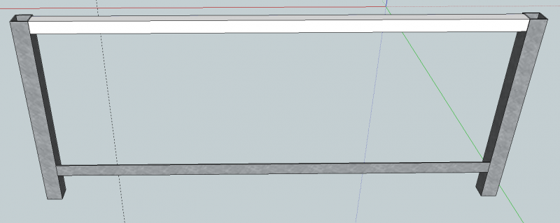
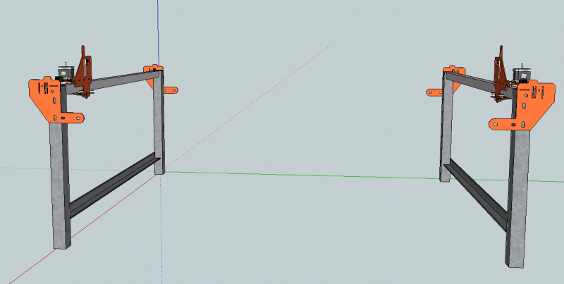
1. Assemble two of the side pieces by welding up 2 of the 638mm legs, 1 of the 1406mm angles spaced 100m off the floor, and 1 of the 1406mm 38x38 pieces on the top. Look at the Bot aligned to what will be the outer facing edge of the legs:
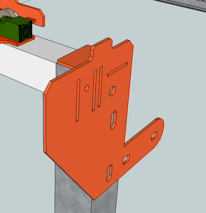
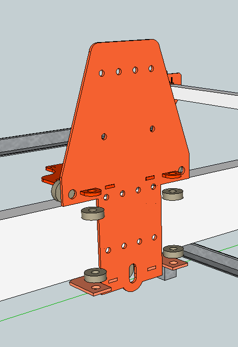
2. Assemble and weld up the two Y Carriages. See the sketchup model for exact details
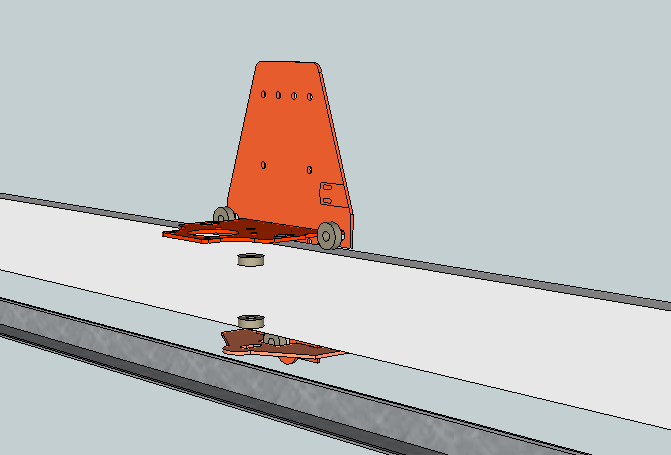
3. Install the Y Carriages onto the 38x38mm rails:
4. Drill and bolt on the Belt mountings to the ends of the side pieces
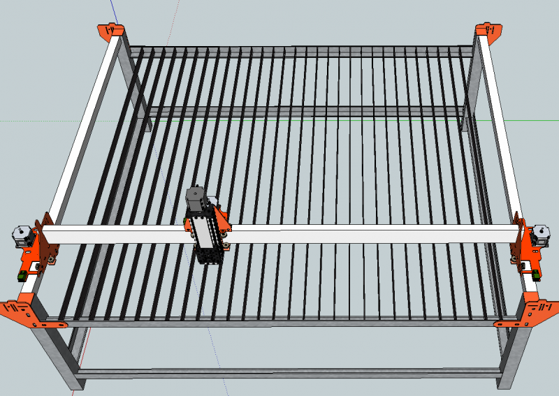
5. Stand the two assembled side pieces upright - a helper or two, or a jig, would help greatly. Space them with 1660mm between them:
6. Drill and bolt in the top 40x40 equal angles (1660mm) between the two pieces
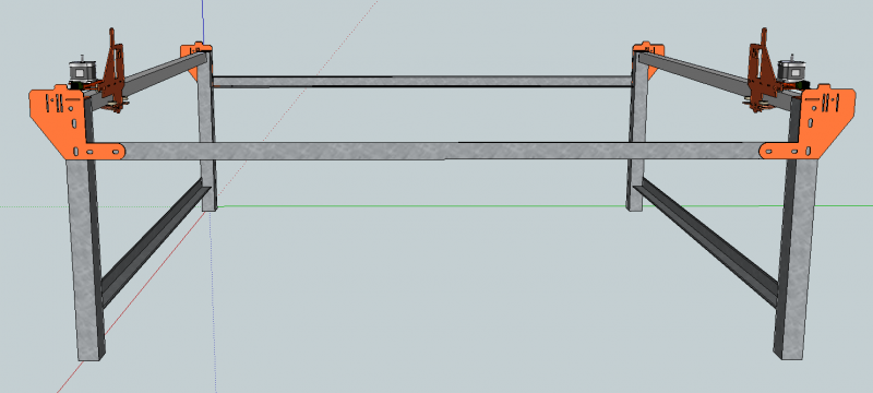
7. Tack weld in the bottom 40x40 equal angle pieces (1660mm long). NB: only tack, we need to square up the gantry before final weld
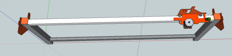
8. Slide the 76x25mm piece into the Y carriages. Tweaking with a grinder may be needed, should be a tight fit. NB although the picture shows the motors installed, it might be easier to do this without the motors

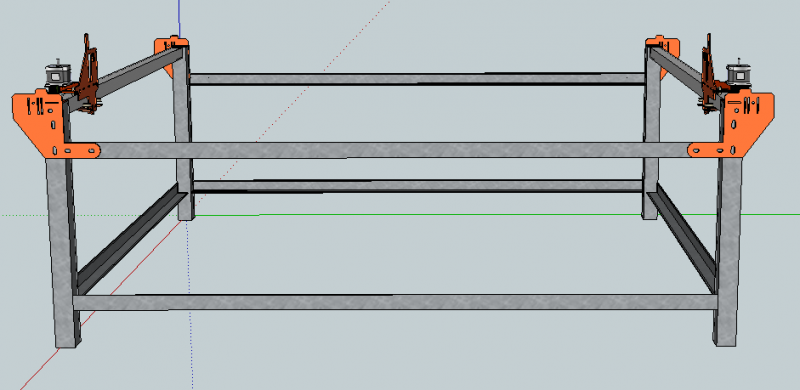
9. Square up! Tack weld the 76x25 piece to the Y carriages on one end of the table. Move it over to the other end of the table - since the top rail is only bolted in - you should be able to adjust for squareness, levelness, and equidistant width between the two Y rails at this time. Make sure the X rail on the Y carriages freely, but securely (no wobble) moves from one end of the table to the other
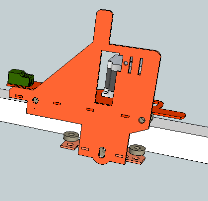
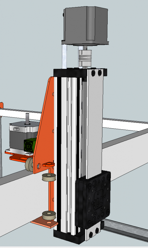
10. Assemble and weld up the X Carriage, and install it onto the X rail:
11. Install the C-Beam Actuator (Z Axis) and the X motor and endstop:
12. Install the cutting bed pieces (1500mm pieces of 30x3mm flat bar). Spaced with 50mm between them, you would need 26 pieces. Tack weld them to stay upright or weld in 50mm spacers to make them stand up between
I will post photos of how to route and install the belts etc once the pulleys and belts arrive, as well as more step by step of welding up the carriages. Watch the Discussion tab for more information!
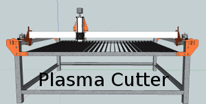
Plasma cutter - 608 on steel tube version
Build in 'Plasma Cutter Builds' published by openhardwarecoza, Apr 20, 2015.
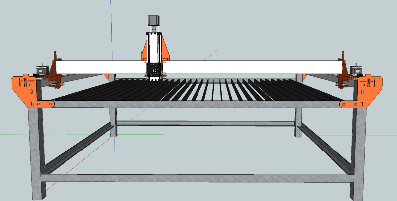
CNC Plasma cutter: 608ZZ on steel square tube linear rollers Welded frame HDT2-15 Belt Drive Tradeweld Cut-40 Plasma cutter with converted hand torch Virtual Torch Height Control through inductive probing - open source electronics project
-
-
Build Author openhardwarecoza, Find all builds by openhardwarecoza
-
- Loading...
-
Build Details
- Build License:
-
- CC - Attribution NonCommercial - CC BY NC
-
Attached Files:
