
Raspberry Pi B+
Before I begin with anything I wanted to share a recommendation and a concern. I am using the Raspberry Pi B+. I suggest that you work with the same Pi. The reason being that certain programs and/or hardware may not currently support the Pi 2. Also, working with Model B vs the B+ may limit the amount of outputs available to you. Not to mention you may need an additional powered USB supply since the model B only has 2 USB ports. Who knows after this beast is put together I will run some testing only to realize that I will not be able to take advantage of the additional USB ports provided due to overheating, this is a build remember so we will learn as we go. Once you get a bit further into the reading it may look like I know what the heck I’m taking about, but I will have you know I’m a bricklayer by profession (www.strictlystone.com), my company. So please cut me a break and let’s use the discussion board to correct inconsistencies and provide any updates or fixes. Currently (at the time of your reading) I am not sure if being limited to a Pi B+ is truly the case but let’s just err on the side of caution. I am also running the latest version of Jessie OS. Please be sure you Pi is equipped with that and you are ready to begin.
Please note that the Red colored lettering represents Linux commands that will be entered into the pi terminal or terminal emulator such as Putty. Don't worry you don't need to proficient at Linux. As long as you can access the terminal and copy and paste commands into it you will be fine.
Part 1 - Install, Enable and Test Camera
If you have not already done so you should Update and Upgrade you Pi so you are able to take advantage of the latest features available to you. Input the following command: (if it prompts you hit Y and enter, depending on how out of date your Pi is and how fast your connection speed is will determine how long it takes to upgrade). Mine took 35 minutes.
sudo apt-get update && sudo apt-get upgrade
Installing and Enabling Camera
Let’s begin by connecting the camera module to the CSI (Camera Serial Interface) port, located behind the Ethernet port. In case you want to see a video by the folks at Raspberry Pi of how to plug it in, I attached it below.
Once that is complete you will need to be connected to the internet by Ethernet or WiFi to perform any of the following functions. Assuming your terminal is open, open the terminal and access the raspiconfig tool by typing the following:
sudo raspi-config
The “sudo” is required because you will be changing files that you do not own as the "pi" user. Once there you will see a list of options. Select Enable camera and hit Enter, then go to “Finish” and you'll be prompted to reboot. Do so to enable your changes.
Now your camera is ready to be tested. There are 2 commands that Pi has for the camera. The "raspistill" function and the "raspivid" function. Type the following into the terminal.
raspistill
You will see a list of options for your still photos. You can pre-determine size, quality, file type as well add a host of effects. For the sake of this test we will not be messing around with any of that. You can choose to do so once your camera is completely installed. Let’s go ahead and take a still photo. Position your camera to make it capable of taking a picture of something. Type the following to snap a pic:
raspistill -o testimage.jpg
If you are working direct off your Pi (not on an emulator) you will see a preview window pop up for a brief moment. If the picture is backwards and you don't want to mess around with physically moving the camera you can make it horizontally flip with this command instead.
raspistill -o testimage.jpg -hf
Since you did not change the file name it will automatically be over written. You can also have the image vertically flip if needed. Simply type "-vf". You can use both commands together so you command would look like this:
raspistill -o testimage.jpg –hf -vf
(testimage.jpg)
As I mentioned before, if you are working of the desktop user interface or in the terminal of the Pi and not an emulator you will see preview window pop up displaying the image or video you are currently taking.. If you are working on a terminal emulator you will not see anything just a small delay. Now that you've taken a picture lets shoot 10 seconds HD video. When finished we will take a look at the results of both. First, have a look and see all the options available to you for taking HD video.
raspivid (check out all the options, nice!)
Again, you can later come back and adjust if needed. Now to film the video type the code below. This will shoot a 10 second video. Since Pi calculates time in milliseconds we need to register 10000 milliseconds to equal 10 seconds.
raspivid -o testvid.h264 -t 10000
(testvid.h264)
Ok, lets have a look at our camera skills. If you are not there already, load the Pi's user interface or desktop as others may call it. Ignore this command if already at desktop.
startx
Now go to the File Manager folder at the top left hand corner of the desktop (cabinet looking icon) In there you should see a JPG called "testimage.jpg" and a video called "testvid.h264". Open them to view them in the Image Viewer. Please note that if you have trouble opening them you can chmod the folder where the images are saved so you have permission to write into it. Otherwise you can do it the lazy way (and sometimes dangerous) which is to add the word "sudo" in front of the command and re-run the previous commands.
Pi does not recognize h264 files. So you will not be able to click on the video and view it. You will have to go to the terminal and run the omxplayer. The following command will load your video in full screen. You can click Cntrl + c to stop. You may notice that the video plays a bit fast.
omxplayer testvid.h264
Side Note: In case you want to convert your h264 file to mp4 you will need to wrap the h264 stream with mp4. You can do that by using gpac. If you have the latest Raspian you should have it pre-installed.
MP4Box -add filename.h264 filename.mp4 (replace "filename" with your file name)
Testing Complete! Camera installed, enabled and working.
Step 2 Installing Web Interface for Camera
Installing RPi Web Cam
Raspberry Pi has many different options out there for web interfaces as well as streaming camera video. Instead of creating my own I selected to go with the "RPi Cam Web Interface" because it just works and very easily. Here is a link to their wiki:
RPi Cam Web Wiki
Installing RPi Web Cam will possibly disable the use of raspistill and raspivid commands previously used, but this program has both of those capabilities built in. Some people say they had issues understanding the installation of “RPi Cam Web” from the wiki so I will rewrite the steps here. As long as you have Raspian "Jessie" OS installed, these instructions will work. Just copy and paste. If you haven't yet updated your RPi here is your chance, do so with the following commands:
sudo apt-get update
sudo apt-get upgrade
Even if you did update your Pi I would recommend getting in the habit, so do it again. Next you will clone the “RPi Cam Web” code from github and enable the install scripts with the following commands: (PLEASE NOTE: remove the X from in front of https. I added it because the editor kept changing it to something else because it thought it was a link, sorry)
git clone Xhttps://github.com/silvanmelchior/RPi_Cam_Web_Interface.git
You just downloaded an installer. You still will have to install the program. With the installer you just downloaded are also 5 separate scripts that are available to use for installation and maintenance functions. There are 3 that you should get familiar with, these scripts are as follows:
So let me show you how to use them. Now that you have downloaded the clone, just go to the folder were you it is located. Type:
- install.sh (for main installation)
- update.sh (check for updates and then run main installation)
- start.sh (starts the software)
cd RPi_Cam_Web_Interface
That takes you to the "RPi Cam Web Interface" directory once there you will have to change the permissions for the .sh files so they can be run. Afterwards you can run the install script.
chmod u+x *.s
./install.sh
FYI: the "./" just means that you are in the current directory where the file is located. If the file was in the parent directory you would type “../install” to run it.
You will have a few option to select from make sure to fill them out accordingly. I used 7000 for the port and Apache for the server. I also made a folder called "camera". Once it is installed you can start the program.
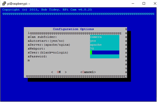
(You should install a user and password if you want to protect your stream)
You can start the service once then do a reboot
./start.sh
sudo reboot
Now the fun part, accessing the cam. All you have to do is go to your Pi's address, put the port you selected as well as the folder. Here is a sample of the structure:
192.168.1.XXX:7000/camera (this is a sample, be sure to use your Pi's address as well as the port and folder you selected)
Smile your on camera!
The web interface for your Pi is complete. Told you it was fast and easy
Part 3 – Making GPIO Pins Web Accessible
Later in the build we will be making a user interface for the control box. The interface be equipped with web based push button controls instead of the more common tactile push button. At the very least that is currently the goal. Whether or not we are capable will be yet to be determined. Basically, the Pi’s GPIO pins will be controlling some relays that in turn control the output of that particular button. Making the pins web accessible will allow us to easily create this web-based interface.
Being web-based will have its advantages. For instance, there will be times that I will not be in the shop and instead will want to sit in my office have look at the progress from in there. Simply access the controller from the web address that you designated and wha-la. Technically you do not have to have it web accessible. You can select to only access the controller from your localhost instead of the web. If so you can wire up the controller with an Ethernet cable and access it through the local network accordingly. I will be fitting my control box with the option to do both, wire it up with Ethernet cable and also attach a Wi-Fi dongle for internet access.
Prepwork
There is a bit of prep work involved with the following steps to make the Pi’s GPIO pin accessible from the WebIOPi. In a nutshell WebIOPi makes toggling GPIO pins on a Pi over the internet an easy task. As of the time of this writing every new version of WebIOPi comes equipped with Weaved IoT Kit. Weaver is basically a developer’s portal that provides internet connection for your Pi, thus it is IoT tool. As of late, there is no need to do a separate install as many tutorials out there on the web recommend. Go to the Weaved website now and create an account (Remote Manage Networked Devices Anywhere). It is free and very helpful and easy to do, not to mention required for internet connectivity with WebIOPi. Once you establish your account the email used will be considered your login. Also take note of the password that you used as it will also be required later in the install of WebIOPi.
Getting Latest Version of WebIOPi, Downloading and Unzipping
First off you will want to begin by going to the WebIOPi site to get a visual on what the latest version is. You will want to make a note of the version number. The one below is "0.7.1". Replace the version in the code below with the latest version as this tutorial may be old by the time you are reading and the latest version will be different.
wget http://sourceforge.net/projects/webiopi/files/WebIOPi-0.7.1.tar.gz
Cool, you now have the tar ball in the root directory of your Pi, now you need to unzip it. Again replace my version number with you version number.
tar -zxvf WebIOPi-0.7.1.tar.gz
Installing WebIOPi
Time to install this MF, lol. Go to the WebIOPi directory. Then run the install script.
cd WebIOPi-0.7.1
./setup.sh
It will ask if you want to continue with the port assignment. Unless you are running a server at that port location you should be fine to hit "Y" and continue.
Next it will ask for the login of your Weaved account that you previously set up followed by your password. After which it will ask you for an alias for you device. An alias is basically a name for you device. Name it what you want to, I don’t think spaces matter. Keep it short and simple as you may be referencing it in your code. I named mine "CNCC" which stands for CNC controller. Once setup was done I went to my browser to see if it works and got this error:
(update: 2/21/2016 – I never once referenced the name in my code so I changed the name to “CNC Controller”)
Error:
Connection Failed - Session died or client target port service is not running
So I decided to load the help file to see if I can get to the bottom of this.
sudo webiopi -h
Sure enough I noticed that the “config” file needed to be loaded so the service can be started over the local network.
sudo webiopi -c config
Once the service was started I decided to give it another shot. So I went to my localhost and entered the port number as well as the folder that Webiopi was in and low and behold it worked, great! Here is a sample of the structure:
http://192.168.1.XXX:8000/webiopi/ (be sure to enter your Pi's address)
Please note that you will have to run that previous command in order to start the server over the local network and every time you close your session it will close. Once we have this portion of the build complete we will have it automatically run at startup. Not sure if I will be changing that but for the mean time here is what you should see:
Click on the top link called GPIO Headers and you will be taken to a page that display the Pi's pin layout. Notice how you can toggle the pins to be input or outputs, very neat! The second link is the same thing but in a list which can be easier to work with for some. The last 2 links are for debugging purposes. Wow, it has its own serial monitor.
If everything went well you should now have your Raspberry Pi’s GPIO pins states accessible and controllable through the internet.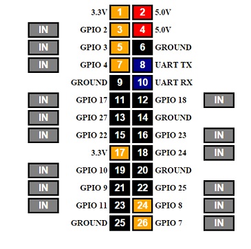
ATTENTION:
After putting together my prototype I started thinking about how I wanted to have the microcontroller or the microprocessor talk back to me. Basically I wanted to add either an LCD Character display or the Raspberry Touch Screen display so that it can feed me pertinent information. Both ways are good so I decided to make part 4 a two part chapter, 4(a) and 4(b) respectively. So moving forward you have two options.
Part 4(a) is about adding an LCD Character display. I will show you how to make it read out 3 temperature points. After much thought I decided upon capturing the CPU, GPU temperatures (of the Pi) and the workshop temperature. The display I will be using is an Adafruit RGB LCD 16x2 display. We will input some temperature thresholds (highs and lows) for each of the readings. And the LCD will not only cycle through the temperature reading, but also turn Red if it surpassed the “high” threshold or display Blue if it falls below the “low” threshold. Sounds like fun, if this is the route you would like to take and keep you controller headless then by all means continue on to 4(a).
Part 4(b) pertains to the installation of the Raspberry Pi Touch Screen. My thought was that since we are adding a web interface, why not add the touch screen so it can run the interface as a sort of software that controls the system. I thought, why not try and take advantage of the cool touch screen capabilities and get rid of the push buttons. Wow, is it possible I thought. Well to be honest anything is possible so let get to it.
Part 4(a) – Adding Functionality [RGB LCD 16x2]
Once your CNC router or machine of some sort is put together and you begin to put it to use you may find it handy to know what the temperature of various components are. This way you can bring the machine to a stop and begin to troubleshoot the possible causes. For example, some temperature data points that you may be want to capture may be the temperature of the Central Processing Unit (CPU) or Graphical Processing Unit (GPU) of the Raspberry Pi. Those happen to be internal temperature readings of the Pi that are accessible by code. Other data points you may want to capture can range from the temperature of the Arduino, router, workshop, stepper motors…whatever.
Dependencies
Now that WebIOPi is installed and running we should move on to locating and installing the correct dependencies needed to run the LCD. Since we are using the Adafruit LCD it is required that we download their LCD module. Also make sure you have the RPi.GPIO library. Lets do both (be sure you are in the root directory by typing “cd”):
sudo apt-get install build-essential python-dev python-smbus python-pip
sudo pip install RPi.GPIO
Once the dependencies above have been installed you can install the character Adafruit LCD module by executing the following commands on the device: (be sure you are in the root folder, type "cd")
git clone XXXhttps://github.com/adafruit/Adafruit_Python_CharLCD.git (please remove XXX)
cd Adafruit_Python_CharLCD
sudo python setup.py install
Reading and Displaying Internal/External Temperature Data
We will be using a Dallas DS18B20 temperature sensor to read external temperature data (workshop temperature). We will also be using some python code to gather the internal temperature of both the Central Processing Unit as well as the Graphics Processing Unit of the Raspberry Pi.
Now that we have the required tools needed to operate the LCD we can begin to make the proper folders and files to test out the LCD. Go to your WebIOPi folder which is located in the root folder by hitting “cd” and go to your WebIOPi directory as follows:
cd WebIOPI-0.7.x (sample, use your folder name which happens to be your version. If you don't know just hit "ls" to see whats in the root)
Begin with making a directory inside your WebIOPi-o.7.x folder. We will call it CNC.
mkdir CNC
After that open the CNC directory and make another folder called "scripts". Then you will go inside that "scripts" directory and create a test file to test out our new LCD. After which we will install the proper code to get the temperature right readings we want.
cd CNC
mkdir scripts
cd scripts
While you are in your scripts folder let’s make that test file and have it run some code.
nano test.py
That will open Nano which is a Linux text editor. You will want to copy and paste the following code into it by copying the code going to your terminal and right clicking once. That will paste everything into it. Just give it a second as nano is slow. You can now save by "cntr-x" to save and when prompted hit "y" and enter to save. If you enter "ls" in the terminal you will see the file you created.
Update:
2/23/2016
I created an account at Github and pushed all the required files there. You can now just go into your scripts directory and perform a "wget" command.
wget PiDuinoCNC/test.py at master · arizno/PiDuinoCNC · GitHub
Cool, you should see a "test.py" file in your scripts folder/directory.
I will be honest I do it totally different. My time is precious so I needed a fast way of getting files, correcting them then saving them on the Pi. Let me show you a cool and lighting fast way to add and edit files from your Pi on your home computer. Forget about using the archaic and slow FTP process. First off you must go and download a text editor on your computer called Sublime Text 3. Once you do that you will want to install a script called Rsub. What Rsub does is that it allows you to simply add the word “rsub” in front of the file name in the Pi terminal,and as long as you have Sublime Text running/open, it will open the file ready for you to create or make changes.
That is nice that you can type 4 letters and have you file open immediately in a text editor. And when you want to save it back to the Pi you simply “Save” your file (Cntrl-S)…wow. I will add the link to a site that explains the process.
I highly recommend this technique as it will save you a bunch of time.
Sublime Tunnel of Love: How to Edit Remote Files With Sublime Text via an SSH Tunnel | Limina.Log
Here is what that code looks like.
You will have to change (line 10 of the code) the "sys.path.append("/home/pi/WebIOPi-0.7.1/CNC/scripts")" to match your location in the event that you did not name your folder "CNC" or if you have a later version of WebIOPi then your system path will be different. That is in part because the folder name includes the WebIOPi version as a part of the folder name (i.e. WebIOPi-o.7.1 folder).Code:# -*- coding: utf-8 -*- # Imports import time import sys sys.path.append("/home/pi/WebIOPi-0.7.1/CNC/scripts") import webiopi import lcd # Initialize LCD display lcd.__init__() # Retrieve GPIO lib GPIO = webiopi.GPIO # RGB LED GPIO pins RED = 11 GREEN = 9 BLUE = 10 # Sets LCD display text color def setColor(rgb): GPIO.pwmWrite(RED, rgb[0]) GPIO.pwmWrite(GREEN, rgb[1]) GPIO.pwmWrite(BLUE, rgb[2]) # Called by WebIOPi when service starts def setup(): webiopi.debug("Script with macros - Setup") # Setup GPIOs GPIO.setFunction(RED, GPIO.PWM) GPIO.setFunction(GREEN, GPIO.PWM) GPIO.setFunction(BLUE, GPIO.PWM) # Looped by WebIOPi def loop(): try: #LCD background white GPIO.pwmWrite(RED, 0.0) GPIO.pwmWrite(GREEN, 0.6) GPIO.pwmWrite(BLUE, 0.8) lcd.lcd_byte(lcd.LCD_LINE_1, lcd.LCD_CMD) lcd.lcd_string("openbuilds.com") lcd.lcd_byte(lcd.LCD_LINE_2, lcd.LCD_CMD) lcd.lcd_string("Build Anything") time.sleep(2) GPIO.pwmWrite(RED, 1.0) GPIO.pwmWrite(GREEN, 1.0) GPIO.pwmWrite(BLUE, 0.0) lcd.lcd_byte(lcd.LCD_LINE_1, lcd.LCD_CMD) lcd.lcd_string("Dream It") lcd.lcd_byte(lcd.LCD_LINE_2, lcd.LCD_CMD) lcd.lcd_string("") time.sleep(1) GPIO.pwmWrite(RED, 0.0) GPIO.pwmWrite(GREEN, 1.0) GPIO.pwmWrite(BLUE, 1.0) lcd.lcd_byte(lcd.LCD_LINE_1, lcd.LCD_CMD) lcd.lcd_string("Build It") lcd.lcd_byte(lcd.LCD_LINE_2, lcd.LCD_CMD) lcd.lcd_string("") time.sleep(1) GPIO.pwmWrite(RED, 1.0) GPIO.pwmWrite(GREEN, 0.0) GPIO.pwmWrite(BLUE, 1.0) lcd.lcd_byte(lcd.LCD_LINE_1, lcd.LCD_CMD) lcd.lcd_string("Share It") lcd.lcd_byte(lcd.LCD_LINE_2, lcd.LCD_CMD) lcd.lcd_string("") time.sleep(2) GPIO.pwmWrite(RED, 1.0) GPIO.pwmWrite(GREEN, 1.0) GPIO.pwmWrite(BLUE, 1.0) lcd.lcd_byte(lcd.LCD_LINE_1, lcd.LCD_CMD) lcd.lcd_string("") lcd.lcd_byte(lcd.LCD_LINE_2, lcd.LCD_CMD) lcd.lcd_string("") finally: webiopi.sleep(5)
Ok, we still need to install the LCD python module script that is used to control the LCD. Assuming that you are still in the “scripts” folder type:
sudo nano lcd.py
That will create an empty file called “LCD.py”. You will want to copy and paste the script inside. And of course you will need to save by "cntr-x" to save and when prompted hit "y" and enter to save. If you enter "ls" in the terminal you will see the file you created.
wget XXXhttps://github.com/arizno/PiDuinoCNC/blob/master/scripts/lcd.py (remove XXX)
Once that is complete we need to modify WebIOPi config file. Begin by going to the WebIOPi directory located inside the “/etc” folder and edit the config file. By the way, that is NOT the same directory where you created the “CNC” folder, just wanted to get that out of the way.Code:#!/usr/bin/python # # HD44780 LCD Test Script for # Raspberry Pi # # Author : Matt Hawkins # Site : http://www.raspberrypi-spy.co.uk # # Date : 26/07/2012 # # Modified by: arizno # The wiring for the LCD (HD44780 compatible) is as follows: # 1 : GND # 2 : 5V # 3 : Contrast (0-5V)* # 4 : RS (Register Select) # 5 : R/W (Read Write) - GROUND THIS PIN # 6 : Enable or Strobe # 7 : Data Bit 0 - NOT USED # 8 : Data Bit 1 - NOT USED # 9 : Data Bit 2 - NOT USED # 10: Data Bit 3 - NOT USED # 11: Data Bit 4 # 12: Data Bit 5 # 13: Data Bit 6 # 14: Data Bit 7 # 15: LCD Backlight +5V # 16: LCD Backlight Red # 17: LCD Backlight Green # 18: LCD Backlight Blue #import import RPi.GPIO as GPIO import time # Define GPIO to LCD mapping (numbers are GPIO Not Pin) LCD_RS = 17 LCD_E = 27 LCD_D4 = 22 LCD_D5 = 25 LCD_D6 = 8 LCD_D7 = 7 # Define some device constants LCD_WIDTH = 16 # Maximum characters per line LCD_CHR = True LCD_CMD = False LCD_LINE_1 = 0x80 # LCD RAM address for the 1st line LCD_LINE_2 = 0xC0 # LCD RAM address for the 2nd line # Timing constants E_PULSE = 0.00005 E_DELAY = 0.00005 def __init__(): GPIO.setmode(GPIO.BCM) # Use BCM GPIO numbers GPIO.setup(LCD_E, GPIO.OUT) # E GPIO.setup(LCD_RS, GPIO.OUT) # RS GPIO.setup(LCD_D4, GPIO.OUT) # DB4 GPIO.setup(LCD_D5, GPIO.OUT) # DB5 GPIO.setup(LCD_D6, GPIO.OUT) # DB6 GPIO.setup(LCD_D7, GPIO.OUT) # DB7 # Initialise display lcd_init() def main(): # Main program block # Send some test lcd_byte(LCD_LINE_1, LCD_CMD) lcd_string("Rasbperry Pi") lcd_byte(LCD_LINE_2, LCD_CMD) lcd_string("Model B+") time.sleep(3) # 3 second delay # Send some text lcd_byte(LCD_LINE_1, LCD_CMD) lcd_string("Openbuilds.com") lcd_byte(LCD_LINE_2, LCD_CMD) lcd_string("Build Anything") time.sleep(20) def lcd_init(): # Initialise display lcd_byte(0x33,LCD_CMD) lcd_byte(0x32,LCD_CMD) lcd_byte(0x28,LCD_CMD) lcd_byte(0x0C,LCD_CMD) lcd_byte(0x06,LCD_CMD) lcd_byte(0x01,LCD_CMD) def lcd_string(message): # Send string to display message = message.ljust(LCD_WIDTH," ") for i in range(LCD_WIDTH): lcd_byte(ord(message[i]),LCD_CHR) def lcd_byte(bits, mode): # Send byte to data pins # bits = data # mode = True for character # False for command GPIO.output(LCD_RS, mode) # RS # High bits GPIO.output(LCD_D4, False) GPIO.output(LCD_D5, False) GPIO.output(LCD_D6, False) GPIO.output(LCD_D7, False) if bits&0x10==0x10: GPIO.output(LCD_D4, True) if bits&0x20==0x20: GPIO.output(LCD_D5, True) if bits&0x40==0x40: GPIO.output(LCD_D6, True) if bits&0x80==0x80: GPIO.output(LCD_D7, True) # Toggle 'Enable' pin time.sleep(E_DELAY) GPIO.output(LCD_E, True) time.sleep(E_PULSE) GPIO.output(LCD_E, False) time.sleep(E_DELAY) # Low bits GPIO.output(LCD_D4, False) GPIO.output(LCD_D5, False) GPIO.output(LCD_D6, False) GPIO.output(LCD_D7, False) if bits&0x01==0x01: GPIO.output(LCD_D4, True) if bits&0x02==0x02: GPIO.output(LCD_D5, True) if bits&0x04==0x04: GPIO.output(LCD_D6, True) if bits&0x08==0x08: GPIO.output(LCD_D7, True) # Toggle 'Enable' pin time.sleep(E_DELAY) GPIO.output(LCD_E, True) time.sleep(E_PULSE) GPIO.output(LCD_E, False) time.sleep(E_DELAY) if __name__ == '__main__': main()
cd /etc/webiopi
sudo nano config
Once inside you will need to change the #docroot and #myscript lines of code to match the proper file location. Make sure you remove the pound sign (#) in front of each line and change the following lines respectively:
(For Example)
Docroot:
doc-root = /home/pi/WebIOPi-0.7.1/CNC
Myscript:
myscript = /home/pi/WebIOPi-0.7.1/CNC/scripts/test.py
Lastly you will need to scroll down to “Devices” and locate the Dallas temperature sensor line. Remove the pound sign (#) and change the variable name from “temp2” to “Shop".
Hardware, wiring up LCD and Dallas Sensor
Now we need to wire everything up. Below is a Fritzing breadboard layout for the Dallas temperature sensor as well as the Adafruit LCD wired up to a Pi Cobbler (which of course gets connected to a Pi).
Now for some fun! Let’s test it out to see if everything works. We will have to start service to see it in action. Go to the following directory then start the server.
cd /etc/webiopi
sudo webiopi -d -c /etc/webiopi/config
If everything went well your Pi and LCD prototype should look like mine in the video below. Please note the changing text as well as the changing background color.
Error
Some people complained of an error with their Dallas sensor reading. If so simply add this snippet of code to the bottom of your boot config file.
sudo nano /boot/config.txt
Scroll to the bottom of the page and add this:
# w1-gpio
dtoverlay=w1-gpio-pullup,gpiopin=4
Remember that you have a server running so you will have to shut it down if you want to use you Pi for other things so shutdown down the service by doing this hitting “CNTRL –C”. Another thing to remember is to never remove power to the Pi without properly shutting down. Especially once you have your Pi loaded with all the programs you want the last thing you need is to corrupt the SD card and have to re-run every command (like me…twice…ok I lied, three times). There are many ways available such as “sudo shutdown –h now” and “sudo halt”.
If you are in the US, you will also need to edit WebIOPi’s htdocs since they only calculate temperature readings in Celsius. Line 1270 has a “getCelsius” function that adds a “C” after the reading, perfect if you use Celsius where you live. If not, change that to “getFahrenheit” and the letter to “F”. WebIOPi already has pre-written functions called getFahrenheit, by changing that you are telling WebIOPi to use the getFahrenheit function instead of the getCelsius function.
cd /usr/share/webiopi/htdocs
sudo nano webiopi.js
Basically line 1270 should look like this:
this.getFahrenheit(function(name, data){
if (element != undefined) {
element.header.text(temp + ": " + data + "°F");
}
setTimeout(function(){temp.refreshUI()}, temp.refreshTime
Testing is complete. Time to install the proper code that will read the temperature from the CPU, GPU and the Dallas sensor, display Highs and Lows and change color if threshold is surpass.
Ok, back at it. Let download the a file called "script.py" into our scripts folder/directory we created.
cd WebIOPi-0.7.1/CNC/scripts
wget XXXhttps://github.com/arizno/PiDuinoCNC/blob/master/scripts/script.py (remove XXX)
Now that we have the proper code to display temperature data on the LCD we need to go back and edit the config file so it references the proper file, "script.py". Change the myscript line to match mine in the image below.
cd /etc/webiopi
sudo nano config
Great, now just go to the /etc/webiopi directory and start the service.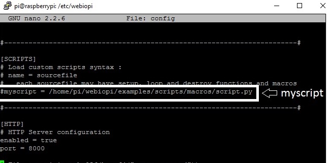
cd /etc/webiopi
sudo webiopi -d -c /etc/webiopi/config
If you are on top of your game your LCD should be spitting out the same thing as mine in the video below. Come to think of it, it will be a bit different for you. My GPU and CPU have reached the threshold limit so color are turning Red. The code is designed to display Green color LCD when temps are normal. It then display White color LCD for the Highs and Lows, since my threshold limits were passed I have Red color LCD being displayed.
As Dora the Explorer would say, "We Did It". **** these kids there getting to my head. Forgive me for that
Coming Soon:
Install pi touch screen & displaying temp data
Install Grbl Software
Create user interface
PiDuinoCNC Controller
Build in 'Circuit - Software Project' published by David Arroyo, Feb 23, 2016.
Using a Raspberry Pi, Arduino and a Protoneer CNC Shield to create an Open Source CNC router controller. It will be equipped with a touch screen to control the on board processor. The touch screen will run a user interface that has buttons for added functionality. There will be a camera for monitoring progress from inside my office. The control box will also feature a way to power the vacuum and spindle/router . I will also be able to monitor room temp as well as Pi CPU temps and averages.
-
-
Build Author David Arroyo, Find all builds by David Arroyo
-
- Loading...
-
Build Details
- Build License:
-
- CC - Attribution - CC BY
Reason for this Build
Wanted to make my own standalone CNC Router fully equipped with is own processor. I did not want the onboard computer for design work just processing power. For tdesigns I would access the CNC router (if you would) remotely from my laptop or desktop PC, which is where the design work takes place.Inspired by
-
Parts list
Qty Part Name Part Link Comments 1 Raspberry Pi http://www.newark.com/raspberry-pi/raspberrypi-2-modb-1gb... Link $35 4 Stepper Motors (Polulu) https://www.pololu.com/product/1182 Link $5.95 1 Protoneer CNC Sheild http://www.ebay.com/itm/Raspberry-Pi-CNC-Board-Hat-V2-51-... Link $32.50 1 Emergency Stop Switch http://www.sourcingmap.com/red-mushroom-cap-1no-1nc-dpst-... Link $4.05 1 Dallas DS18B20 Digital temperature sensor https://www.adafruit.com/products/381 Link $9.95 1 RGB LCD 16x2 https://www.adafruit.com/products/399?q=dallas& Link $13.95 0 Link 0 Link
