
Been a slow start!!! after I ordered the Plates, wheels and motors my bathroom jut/remodel project had some cost over-runs, then the roof leaked and the basement flooded! (not related to each-other, minor flood)
How this project came to be..
I always wanted a cnc router (or laser) but never thought it was affordable. Spring of 2016 a friend of mine ordered an X-carve, but was then told by his new job he would be going to Taiwan for 3 months of training. So he let me set it up and play for the summer, i was hooked!
Lately I was able to get started on some needed cleaning and moving things around to fit this machine somewhere. Not an easy task, small house and way too many RC airplanes.
Table.


Thanks to the bathroom project I had a "mostly" full sheet of 9/16" ply leftover. Just about the ugliest ply I've ever seen but paint it black (Opaque deck stain) and it looks ok for the table base. Cut the ply into 4" and 4-9/16 strips to make angle legs. 4-9/16" strips for the table aprons. I need it to be max of 35" tall so off-cuts from the table saw can be slide right onto the CNC machine, but the way it's facing now that wont work, oh well. I want to be able to take this thing apart to move it out of the basement if needed, so the short aprons get screwed on and I put some diagonals on the short sides to stiffen it up, turned out super stiff. There will be an MDF shelf on the bottom spreaders and the top will be an MDF torsion box/vacuum table and also serve as the "frame" for the Ox.
Still working on the details but so far the 1500mm 2080 Y rails will be supported by 2" aluminum 6061-T6 Angle (3/16" thick) that will be bolted to the table directly. The 2080 will hang off the edge of the table which is 37.5" wide and 48" long. yes 1500 is longer than 48" I really want a small area of table available to do end routing of longish wood or plastic standing vertically like Frank Howarth (YouTube woodworker) did on his CNC setup. the back end of the table where the router can't reach anyway will not have table under it.. Mostly because then the table is smaller and cheaper to make with only about a sheet and a half of MDF.
The bottom legs of the table gets my typical treatment for my basement floor, which is not at all flat. 5/16" carriage bolts nuts and washers make cheap and sturdy adjustable feet The best part about the feet is with the smooth carriage bolts you can slide the table when you want to move it without damaging anything.
to be cont..
I will upload my sketchup drawings once I clean them up
Hardware
stuff i have so far...

ChrisClub Ox Heavyduty plates set including C-beam Z motor mount (4 post mount) and 11 hole corners
Makita 0701 palm router (homedepot) and Elaire collet
GT3 double belts, 16 tooth pinions (ebay)
269oz-inch nema 23 steppers, from valuehobby.com
xtreme wheels, 1/4" eccentrics and spacers (good folks in China)
stuff I didn't buy yet...
Arduino grbl controler with some 542 type driver not sure from where yet, i had good luck with the grbl and universal g-code sender and sketchUcam when i had an X-carve
v-rails
acme rod, probably just go tr8*8 although i like the idea of tr8*4
I need to get one c-beam acme end
bunch of low profile M5 screws and whatnots
Update, not in any particular order... as of Jan-12, 2017
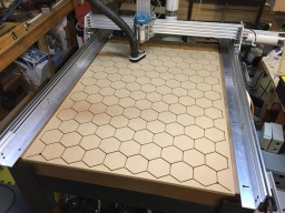
Spoil Board, this will get made when the machine is running.


The (most complicated ever) Spoil board is made of two layers of 1/2" MDF (might have to be 3/4" as 1/2 is harder to find lately) the bottom layer has channels that will be milled out that will clear a T-Slot nut but not let it spin. the upper layer has a slot for the M5 hold down bolt and a larger opening to get the T-nut in and out like a real long Key-way. This way the ends of the board are still contained so the board can function as a vacuum table still. there will be a shallow v-bit carved grid for material alignment and many small holes for vacuum going through all three layers of MDF as well as alignment dowels to get the MDF all aligned so this system works. Hope this makes sense.
The front plate with all the holes is the vertical hold down plate, this will just be simple M5 threaded inserts. I only will have a couple inches of forward travel off the spoil board to do mortises and tendons and things like that. Couple inches is all I need for this, really one inch would probably get me by.
Makita Router mount


Idea here is to have something that works well enough to make something else after it's up and running. Although it turned out so simple and clean i might just make a second out of aluminum or nylon (harder than the HDPE-starboard) to replace it? we will see when i get there.
What i really like about this design;
1) it is that is was cheap, all i had to purchase was the 4" pipe clamps, had everything else
2) it gets the center-line of the router about as close as possible to the extrusion as you can get. I could get slightly closer (1/4") but then i would have to grind the angle brackets a bit. many clamps systems i see have the router way out in the breeze for no reason, this adds leverage to twist the Z-axis. . Distance i'm talking about in this pic..

Update Jan 14, 2017
Double-Belt
Going to be using the double-belt setup, was going to use double sided tape as most people do, but I have this CA glue I wanted to try. Turns out it that makes a permanent bond to the neoprene belt. I had to pull hard to separate it and it takes rubber along with it. This test was after 2 hour drying, after 24 hours it should be even stronger. The glue is med viscosity and it has some tack that should make installing it real easy. This CA is Bob Smith Industries (re-branded with my local Hobby shop) and is available at most hobby shops, if they don't have this type any RC Car tire glue should work just as well.
The question is does the system work better with the tape due to the thickness of it? this would be even thinner than the thinnest tape. I'll have to try it when i get my extrusions, which should be in a couple weeks.


Update Jan 26, 2017
I had Monday morning free to finally pick up the needed MDF for this project. Picked up 3 sheets of 1/2" MDF and a sheet of 3/4" and 1/2" 5x5' Baltic Birch Ply. This is the first Baltic Birch I've ever had, and you know you are a Maker/Woodworker when you get really excited about getting plywood! I didn't have projects in mind for the ply but I knew I needed a Skill saw track and a new table saw sled. Started cutting the MDF up yesterday and today. I have the major top and bottom of the torsion box cut, the bottom shelf, and most of the box webbing cut. should start gluing that up tomorrow. Some pics of the track with aluminum U channel runner guide and the sled, with holes drilled for M5 bolts at 10 and 30mm off the sled to hold V-Slot with T-nuts.
Update Jan 27, 2017
Finally got the torsion box going! All the holes are there for the vacuum board feature.. so the whole t-box will be a vacuum board kinda..
Had to call it quits for the night as the kids went to bed and the table saw is right under my son's room. I need to adjust the length of the last four small members then, i can finish the glue up. No fasteners just some light clamping and weight.
About the holes, at first i figured the 2" Forstner (harbor freight, LOL) would work ok, but I figured it would be a struggle. Oh Boy, after the first hole i thought i might need to try something else because it was really bad. Smoke, heat and not much cutting, stalling out the drill press.. figured I would try sharpening the bit, few swipes with a small file and tried it again, 100% better! went from one hole taking 3 minutes to 10-15 seconds after sharpening


Jan 28, 2017
good day today, got a ton done with the torsion box (t-box). To bolt the ox to the t-box I put four M5 T-Nuts on each side where the 2" x 3/16" angle aluminum will go. The t-nuts are glued to small squares of 1/4" birch ply so they don't fall out into the box and the ply adds some strength over just 1/2" MDF.
After the squares were installed and glue drying I worked on the jig to route slots into the aluminum angle so there is some adjust-ability to the location. Used scrap MDF and hotglue for the jig, using a 1/8" carbide bit for the routing. I didn't cut the slots yet because i'm not 100% how much overhang I need.
I trimmed the ends of the aluminum angle using my 10" aluminum cutting blade, put up a pic of the cutoffs to show the surface the blade leaves.
Glued the bottom of the t-box on (built upside-down) used a couple scrap sticks to keep it off the glue until the alignment was right then pull the sticks out and clamped and weight down with everything around.
Once the glue is dry (ish) i started trimming the top and bottom with a flush trim router bit, sanded a bit and broke the edges and corners with a sanding block and 100 grit. I'm really happy with how it turned out. My wife is making me spread out the purchases so much it gives me time to do things more carefully than i might have otherwise.. got to make it a positive some how!


Jan 28th Nightly Update
kinda screwed up on the aluminum angle slot location, didn't have to make them so long, but they work. The other side is just holes for now, should not need slots on both sides. Slots were not too bad to cut, used a 2 flute spiral-up carbide 1/8" bit, and did about half a mm at a time. The hardest part was just being precise with the depth of cut, not easy with this trim base, and keeping it clean. Did the cutting at a RPM setting of 2 on the makita and "slow ipm, oh and lube was marvel mystery oil.
Table fit great in the base very solid. The blotchy nature of the top finish is from not waiting long enough between coats of shellac. wont see most of it anyway once the spoil board is on it


2-2-2017 Dust Collection!! Update
I had the 20% off coupon and Harbor Freight actually had a 2hp dust collector in stock at the same time, for once... doing the obligatory 2nd stage mod, turning the bag/filter can into a vortex like thing with a Thien baffle and a garbage can. a youtuber April Wilkerson does a great video on making this mod, mine will be very close to hers but can't put mine outside so i have to build a filter box probably going to use furnace filters. Making a dust collector turned into a really dusty project, there is irony for you.. you can see the angle aluminum brackets i added, those are to hold the top on as i might want to change the setup if this doesnt work out. Most Thien setups use a tube that goes through the lid and is inserted about 1/2 a diameter. i used the plastic exit adapter for my inlet, should work but just in case, i can change it later. the bottom will just get siliconed in solid. This website has a good diagram, Hector's Thien-baffle shopvac
Mr. Thien Himself...
J. Phil Thien's Cyclone Separator Lid w/ the Thien Cyclone Separator Baffle
My Pics..


BIG UPDATE! Feb 11, 2017
Parts order arrived!
All I have left to get is cable chain, PSU, stepper drivers.. and some 15mm screws..
I ended up just gluing the 1000mm X gantry rails together with Med CA glue. Was really nervous that i would glue it off from parallel because the work time is so short, but using tape as a hinge and a flat table i was able to get it together really nice, carriage runs very smooth with 9mm spacers in-between the wheels.
I was going to use Epoxy, i have a gallon of West System under my bench, but that would have taken 4 hours (206 hardener) or more like overnight at the temp my basement is to cure. There is plenty of surface area for the CA and it turned out great, if i had to undo it the nice thing with the CA is a heatgun should make it let go. I cut the rails after they were glued and using the new sled with the slot nuts and bolts, worked out perfect.
Was able to experiment with some different thicknesses of material under the bottom dual belt. I will be trying 5x0.6mm pulltruded carbon fiber as a base to raise the belt up so the pressure on the wheels is correct. This seems to be perfect for my wheels and rails, I will be using the glue mentioned before.
I never had felt V-rail extrusions before, and was pleasantly surprised with how stout they are and how stiff this build is turning out. Big step up from the X-carve and for about the same price! The c-beam Z is super OX like


Update Feb 25, 2017
Been swamped at work with travel and an unexpected honeydo project, but getting there!
Did the dual belt on the X gantry and started the Y, should have that done tonight. My first try i was a bit rushed and screwed up!! i used way too much glue then i could not get the carbon strip to tack up, so it was floating on the glue. then i panicked and used kicker! big mistake, made a mess, luckilly you have 4 chances
these act just as 0.6mm spacers to get the dual belt system to ride with good wheel pressure, keeping the belts together securely. On the Y-plates i drilled and tapped M4 holes to use as hold down screws for the belts, with little brass shims over the belt, works ok. Not 100% sure what i will do on the Y rails yet.
Figured out the dust collection shoe mounting. A 6" long section of 2040 gives easy vertical adjustment and the 9mm thick acrylic shoe will mount to the bottom of it, will have bristles like the x-carve one i made last year. Drilled and mounted a section of 3/4" 6061 angle to the Z axis wheels. so the mounting point doesn't move in relation to the Z axis. If the shoe moves with the Z you end up smashing the bristles into the work as it cuts deeper or having to set it higher to compensate.
Mounted the 15x30mm cable chain. Not sure how others are mounting the end on the X-carage but found i could file out a bit of aluminum from the rear gantry plate at the top cable keeper detail so i could get 20mm spaced M5 bolts on there with a short section of the 2040 for a mount, worked great. for the other end its just t-slot-nut and 8mm bolt on the rear 2060 gantry support and a corner bracket, worked out very clean. On the Y axis plate i used another short 2040 section and used a couple of the bolt holes intended for angle brackets.. basicly it goes angle bracket, Y-plate, 2040 section, all bolted with 2 20mm bolts. had to build a small 32" long shelf out of some cutoff 1/2" baltic birch ply, panted it black and mounted to the side of the table for the chain to rest on.
Regarding bolts, why did I order every size except 15mm!!! ordered 100 yesterday


March 5, 2017 Update
Don't you love when you have a whole post written and then you close the window while waiting for the pics to upload? so second try

Finally was able to order all the stepper drivers for the project, due to the excellent service and to support Openbuilds I opted for the excellent DQ542MA. This pic shows the first wire up test i did, I think i'm running in 1/8th step here. My plan is to use 1/16 on X-Y and 1/8 on Z. this gets you ~66.666 steps per mm on the X-Y (0.015mm per step) and 200 steps per mm on the Z (0.0005mm per step). I could go with 1/4 step with the Z and be good with resolution.

Used my old 4" grinder with a metal cutting wheel and a step drill to make the openings.. there are some random drill holes in these boxes as they were used at work for something else.

Holes drilled for the meanwell 350-24, the holes tapped on the PSU are M4.


Used some extra 1/4" spacers i had to get the PSU off the wall to improve airflow.
found these cheap and nice fan covers on Amazon they were $7 for 5


re-using some cable glands

120VAC cable

90mm fan also re-used, 24v it cranks lots of air.


laid out the screw locations for the drives, arduino and arduino relay module using the caliper to scratch out the lines on a 1/8" thick aluminum plate cut to fit inside the box on standoffs.
After scratching out the locations center punch the drill locations


then drill with 1/8" drill
then tap with 6-32 tap, going to reuse some PC case screws and standoffs, they are 6-32 thread


I ended up not using the standoffs shown at the arduino location because the arduino has very small holes, i made some out of plastic tubing and rc servo screws later.


Mounting Stuff, 8 relays... Why? Why Not? so cheap to get the 8 channel one.

Epic Build Mess!


Cut stepper wires to length, Driver power, each driver has its own pair of wires to the PSU 18AWG is plenty.


This is the basic schematic of the Arduino wiring for reference
Update March 11, 2017
She works!
Things i still need to do;
1) Make a dust collection shoe
2) wire up the dust collection, spindle, and vac table relays, in another nima4 box
3) make the spoil board
4) install E-stop (button on the way)
5) make a better vac table box, better sound reduction and cooling airflow (i have a 120vac fan for it)
6) this list keeps getting longer! Limit or at least home switches...
I Think i will redo the signal wire some day, as it's a bit sloppy, but its working perfectly!
Only screw up was putting the Y signal on the X drives (had to splice in the grey wire), took half an hour to figure out why my X would not move when I was testing the z and x only. Still a couple things to clean up and finish, like landing all the grounding wires to the motors (just something I like to do). The 8 channel relay arduino board will be used to send 24v signals to the SSR's in another box. Also i removed the stock power cord off the Makita ( Super easy! ) and replaced it with some shielded 20-2 wire so i can run it through the cable chains. 20awg should be enough for 5A-120VAC but I might replace it with 18awg for some more headroom, although it's probably fine as is, not going to be pushing the 700watts of this router all cut file long, if ever.


Some Explanation on my wiring..
I wanted to keep this as simple as possible, I didn't use any crimp or ferrules or spads, just tinned wire ends. No extra connectors, when do you really need to unplug a stepper?
In my experience unless you have a good crimping tool (I don't at home) you are kidding yourself with crimps, good tools cost $100 and up ($1000+ for specialized commercial tools).
If you see any spades, like on the grounding, those are crimped (not with a good tool, so basically not crimped) AND soldered and heat shrunk for strain relief.
I know soldering can make the wire more brittle and may break off, but the control cabinet isn't going to see enough vibration for this to happen in 100 years! On the other hand I have seen many ferrules that look great but fall right off after a short while. I have seen 15 million dollar flight simulators held up while hunting down bad crimps on spades in large PLC cabinets. Crimps can be great when done correctly and with the right tools and supplies, but for the home gamer in my opinion they can lead to more trouble than they are worth.
Made the first part with it, and for it, today...
I think it's ironic that most of us spend more time making parts for our cnc machines (at least at first) than for "real" projects.
I needed a clean way to hold the belts in place for the Y, with the dual-belt you don't need to tension or even clamp very tightly, so these end caps just have a snug fitting slot, so the belts are held together well at the ends. They turned out good, about 0.5mm short on the X though, i made a slight adjustment to 67steps per mm instead of 66.666step per mm calculated. will see if this is enough. I know my Y belts went in much better than the X, I got the Ys nice and tight when gluing down. when measuring across large distances both x and y look good, z is dead nuts, even with a dial indicator.
After i installed the parts i realized i should have made a small tab sticking out as a hard end limit, i will make that change and cut four more maybe tomorrow (or not). now i have to draw the dust collector shoe..


Update March 18, 2017
Picked up the hose for the dust shoe today and made the changes in the sketchup file to fit the adapter snug.. got her cut tonight, just going to dump the pics for now, will write details later.. not that anybody reads all this blabbing anyway


Update March 30, 2017
Been really busy with my work traveling so have not been taking too many pics of what I've been doing. Finally have the power box built. This contains a line filter, DIN rail for power distribution, DIN rail mounted 24v psu, two 40A SSR's with heatsinks, bypass switch for the SSR's and a 24VDC cooling fan.
Problem I've run into, so the pin 11 on Arduino GRBL 1.1 is High=on Low=off, the opposite of any other Arduino function. I'm using this output to switch a relay which sends 24V from the DIN PSU to the SSR. When the arduino is connected to the PC GRBL gives the M5 command to go low for spindle off. GRBL does this because the pin 11 is Spindle speed control, but even when set to "0" as max RPM setting (PWM disable) it's still high=on. I can change this in the configure and re-compile, but I will be adding an invert circuit instead, already have the 7404 to do it.
pic of the box , power box is the far one, it's another 12x10x5" nema box like the controller box.
Power comes from a dedicated 20A line I ran to the metal double duplex box screwed to the dust collector frame. I'll take some pics of the inside of the power box if anybody is interested.

Added a screw shield to the arduino, much better and it gives me a spot to put the Logic invert and the hall effect home switch circuits onto, should make for a clean install. The switch i added to the top of the controller box is a dust collection bypass that will let me turn it on and off without the cnc system powered on at all, it's just in parallel with the relay for the Dust collector and that triggers the 40A SSR.
You can see the Dust collection filter box i built, still need to finish that! but it works great!
https://www.amazon.com/XINY-compatible-Prototyping-Universal-Boardproto/dp/B01J9CPHWU/ref=sr_1_1?ie=UTF8&qid=1490897964&sr=8-1&keywords=Screw+Shield+Arduino+Compatible


Update April 17, 2017.. calling it complete!
Been cutting all kinds of things from 3/4" Baltic birch to 1/16" poly carbonate sheet.
I added the side shields which help keep crap out of the belts when not using the dust shoe.
Really happy with how it's running, have not lost one step yet, even when i push the feed rate up 130%
Here are some things i've been paying with.. no major projects yet, and I still have to surface cut my waste board. Any updates or projects from now on will just go to the thread.


OX Heavy Duty Build
Build in 'Cartesian Style CNC' published by Gary Caruso, Apr 17, 2017.
OX Heavy Duty, using Chrisclub plates, for 2080 X-Y and C-beam Z
-
-
Build Author Gary Caruso, Find all builds by Gary Caruso
-
- Loading...
-
Build Details
- Build License:
-
- CC - Attribution - CC BY
Reason for this Build
I design, build and sometimes kit rc model airplanes. you can see my "Sabre" series profile 3D ARF designs on Valuehobby.com -
Attached Files:


