As this is my first CNC build, I could hardly figure out where to start. I did tons of reading and eventually stumbled on OpenBuilds. Seeing other people’s builds really helped me visualize how I wanted to build my machine. A big shout out to Kyo, as his Sphinx build manual was probably the best reference I could have ever hoped for.
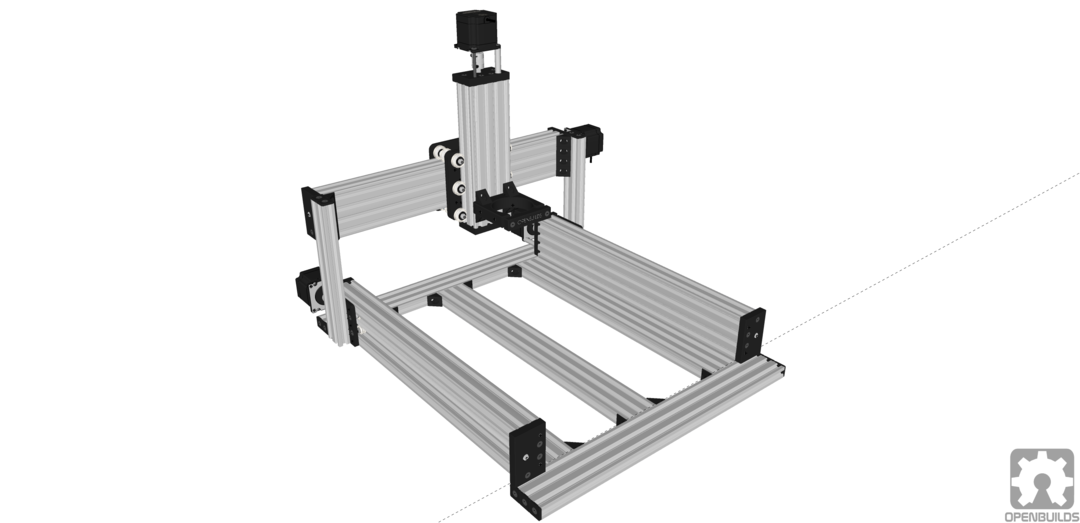
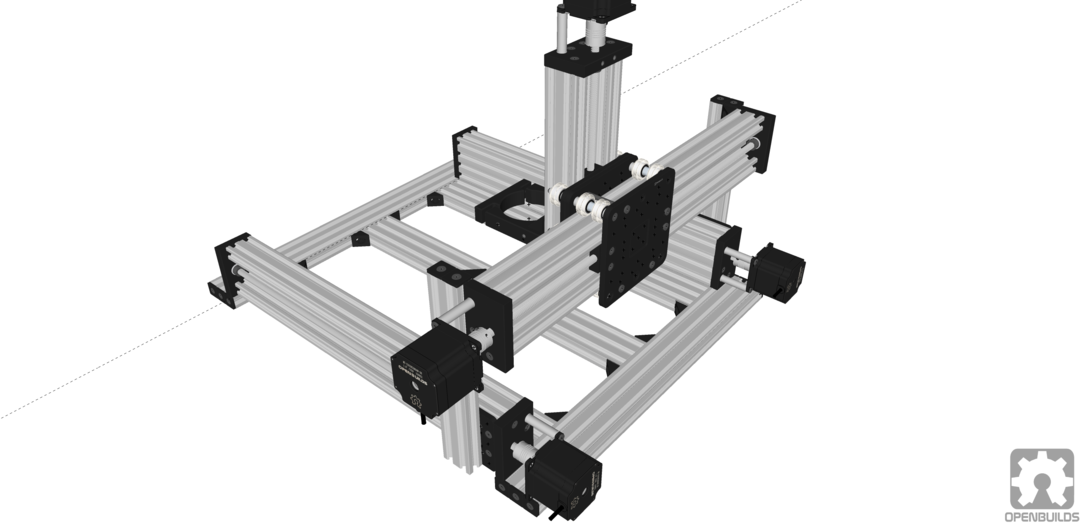
I started modeling the design in SketchUp to help nail down a parts list. The OpenBuilds SketchUp library was extremely helpful here.
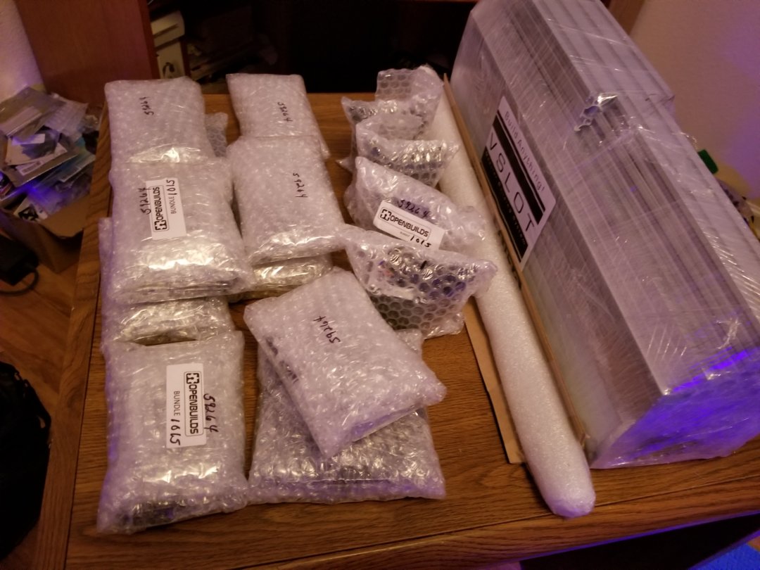
Parts arrived! I had no idea the shipment would be this heavy. Everything was so meticulously packed, A+ on packing the order.
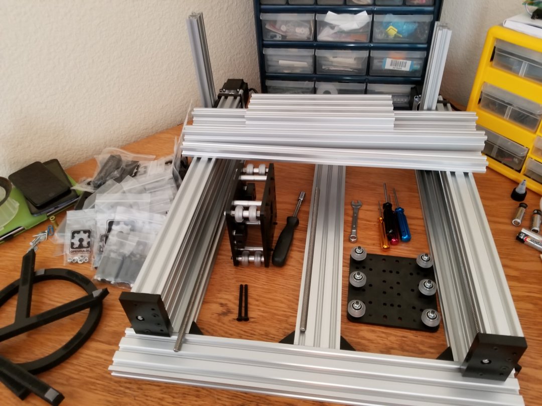
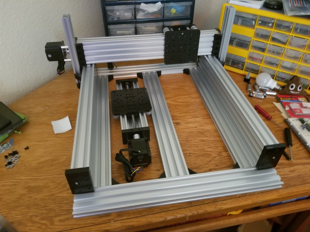
Early test fitting components. The two Y-axis actuators and the base have been assembled. The X-axis gantry can be seen in two pieces here.
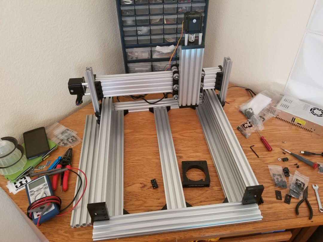
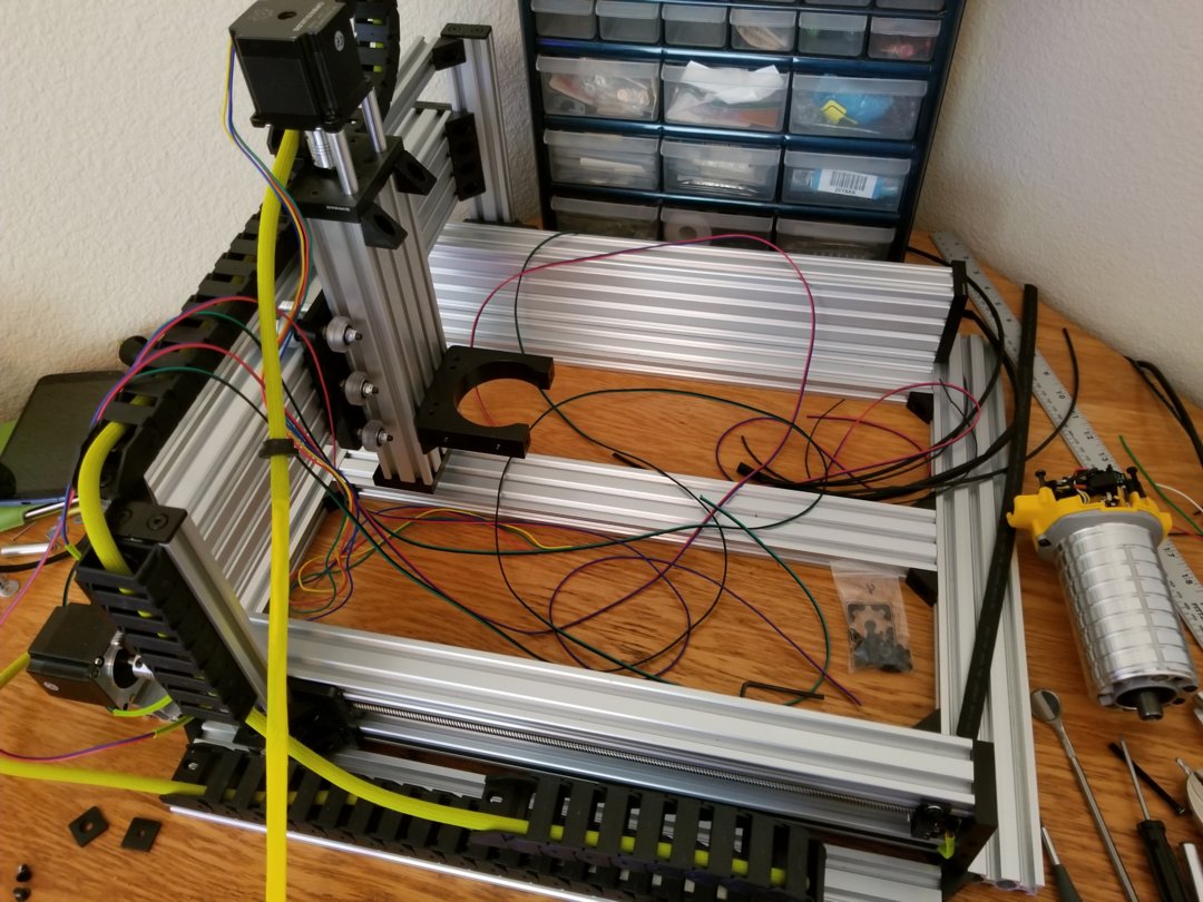
The X-axis gantry mounted and the Z-axis actuator assembled.
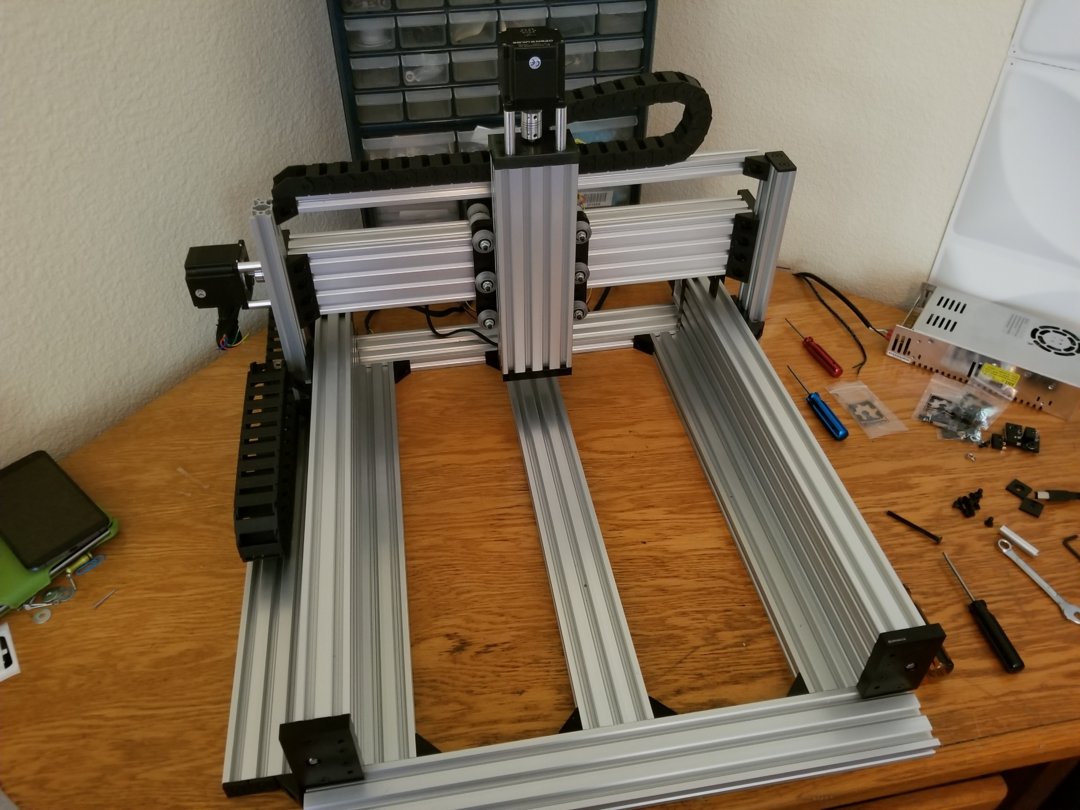
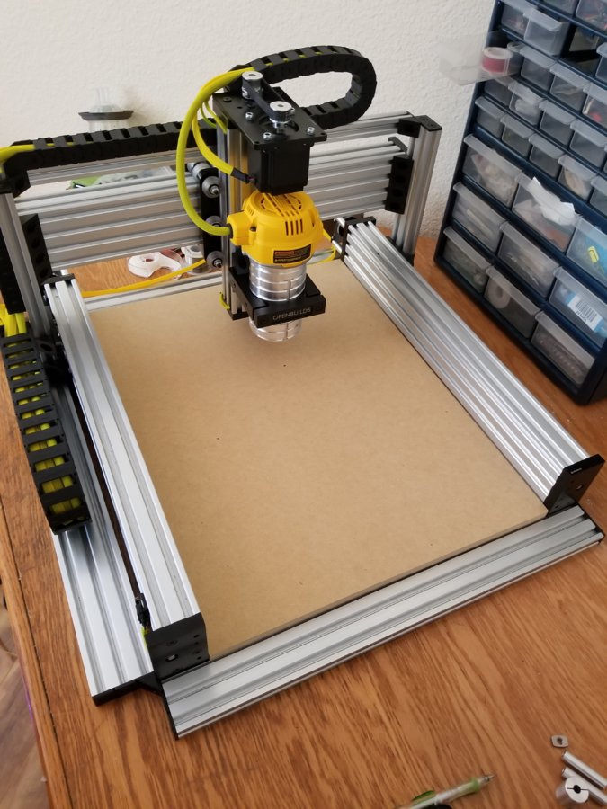
Z-axis mounted
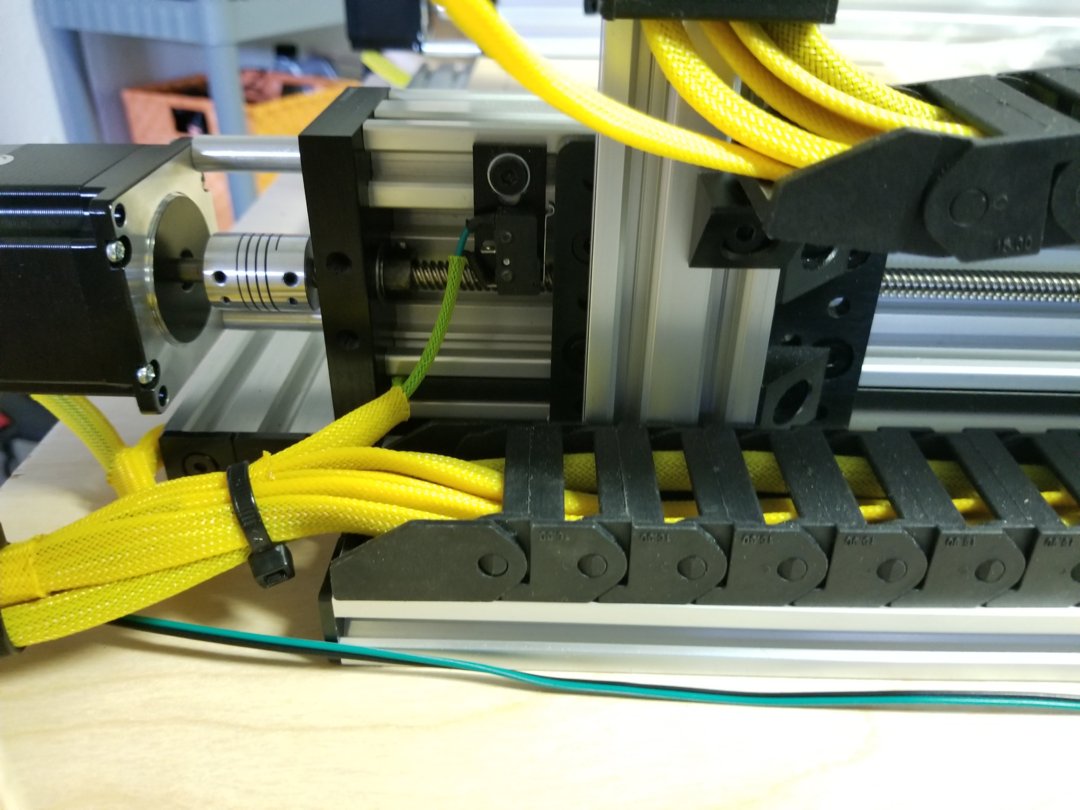
Drag chains added
The DeWalt DWP611
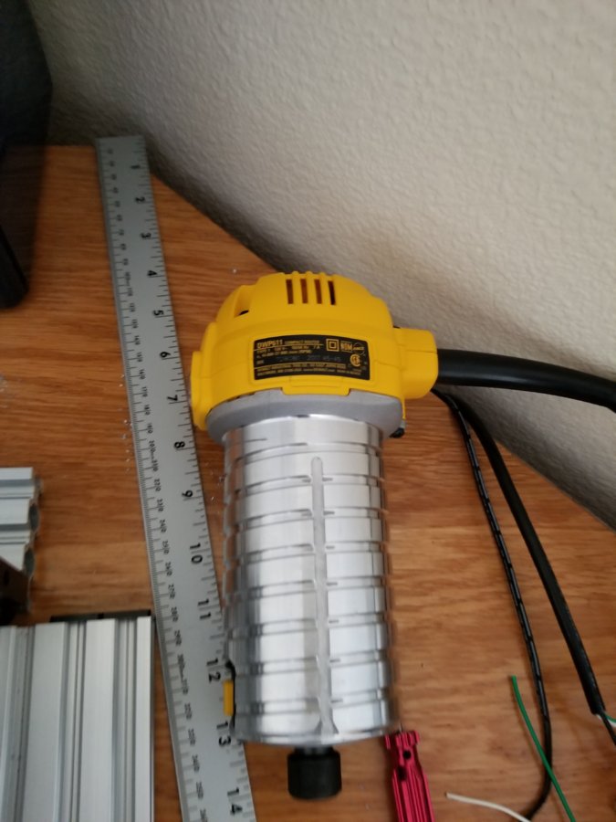
This was the start of wiring, what a mess! I couldn’t stand the overly long rubber boot on the DWP611. You can see the top housing is removed here so I could trim the strain relief boot and place the power cord in braided PET sleeving.
Router and X-axis limit switches pulled through.
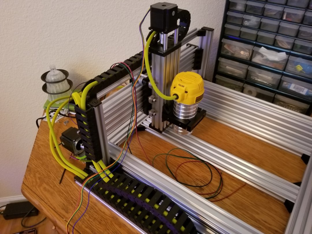
I switched to a stand-off plate for the top of the Z-axis to save some height. More wires sleeved and pulled through.
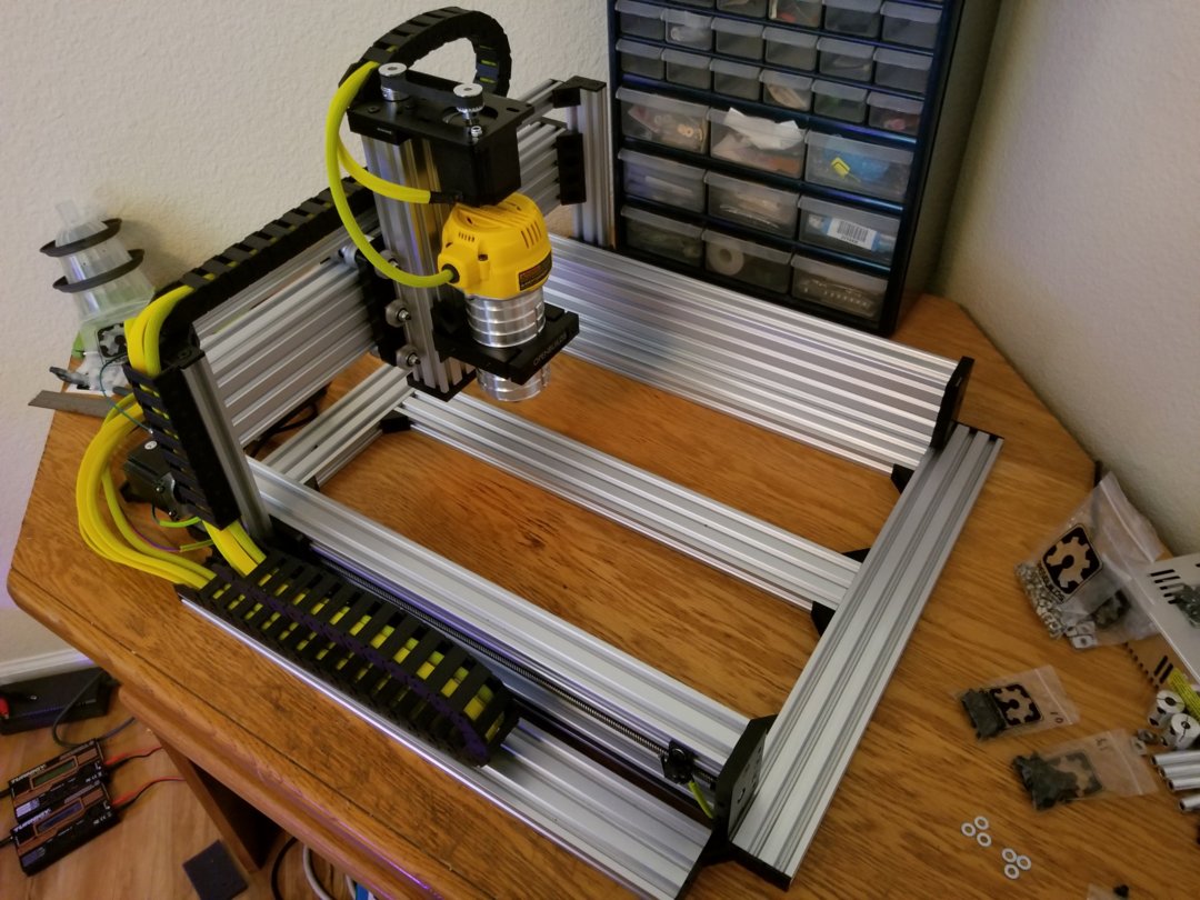
All wiring has been sleeved and pulled through!
½” MDF spoiler board
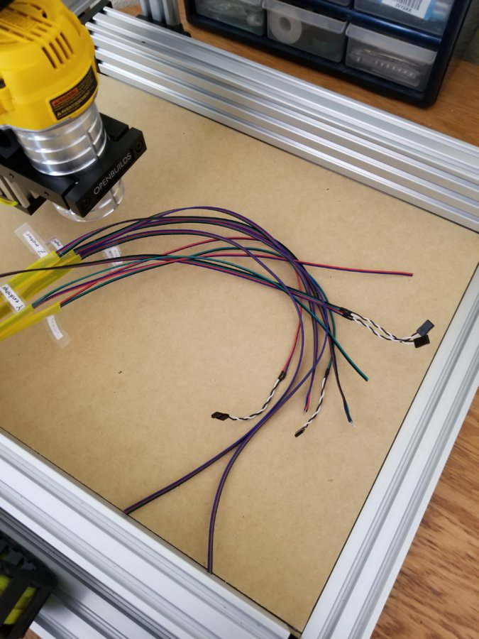
The other end of the wiring needs some attention. At least it got labeled.
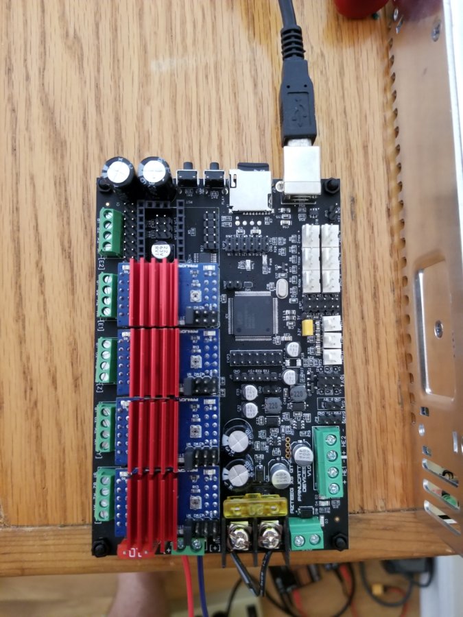
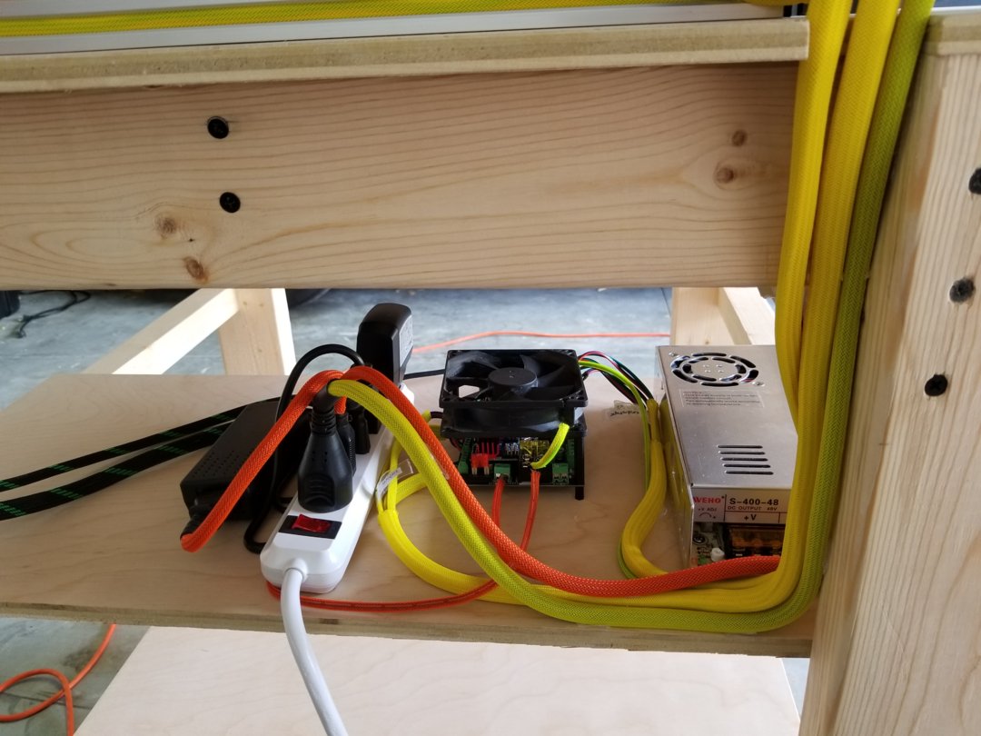
Azteeg X5 GT stepper controller, runs Smoothieware. BSD109A drivers, and a 48V DC motor power supply.
At this point the machine mechanical build was complete and I needed to connect up to the controller to see if everything works as planned.

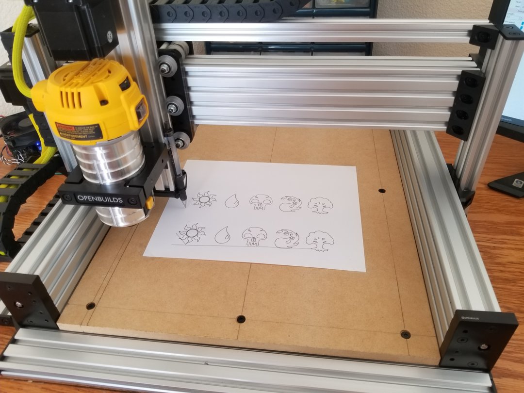
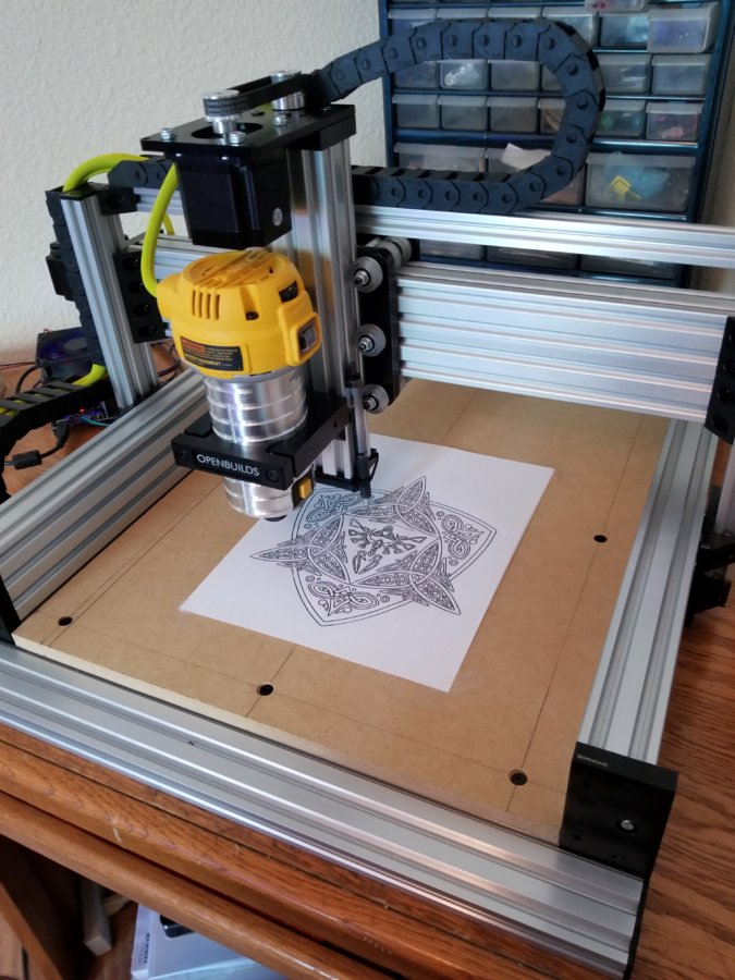
I attached a pen to the Z-axis and fire off some G-code. Everything seems to function.

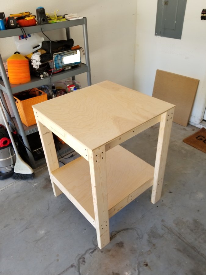
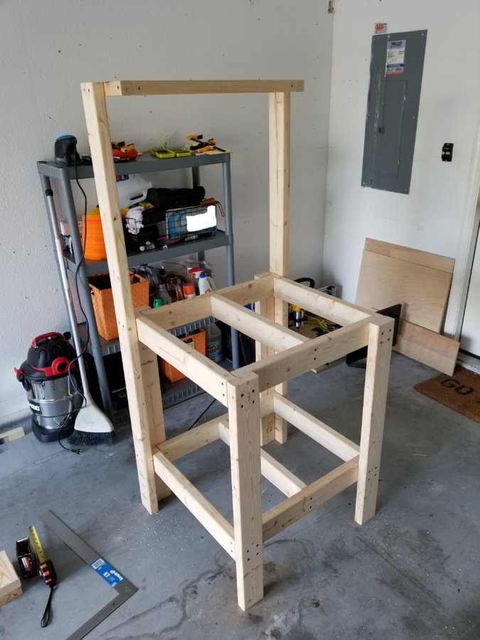
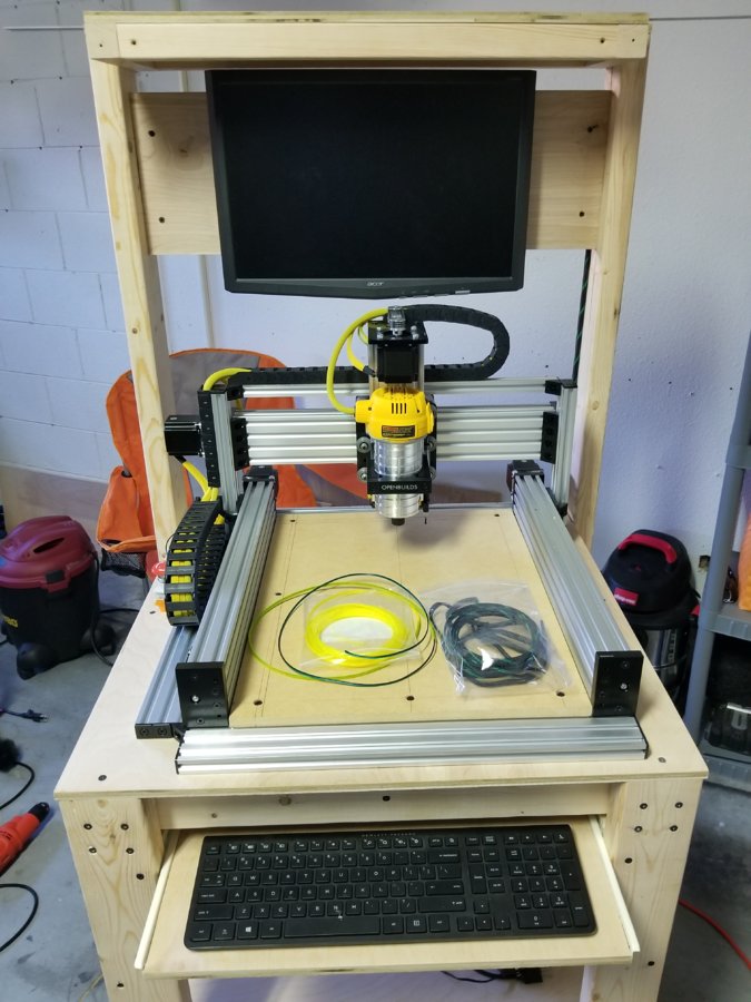
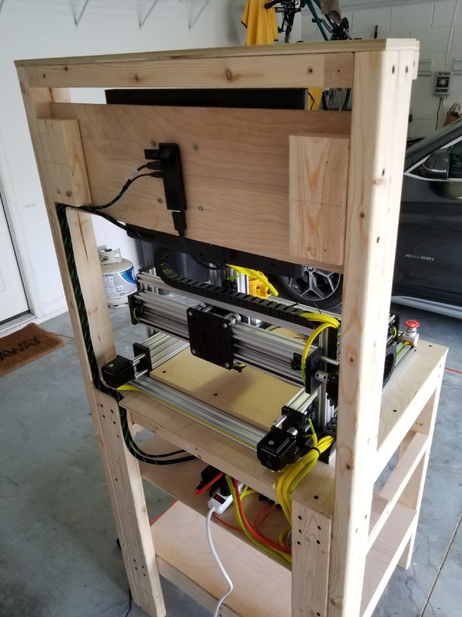
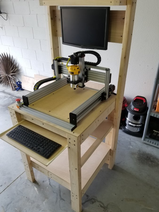
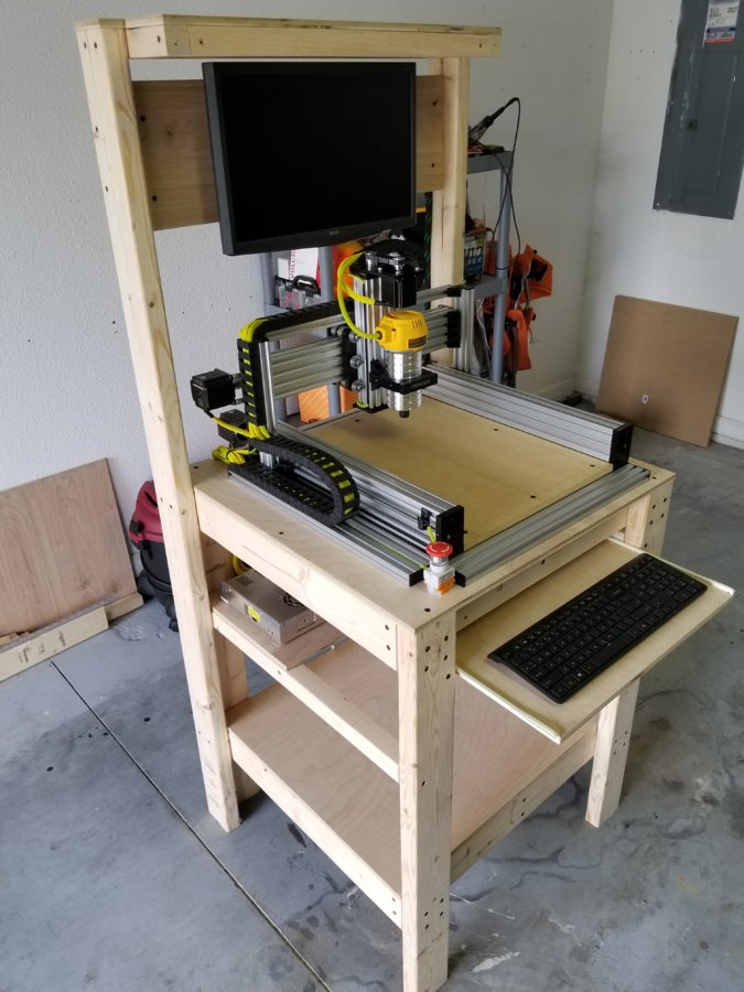
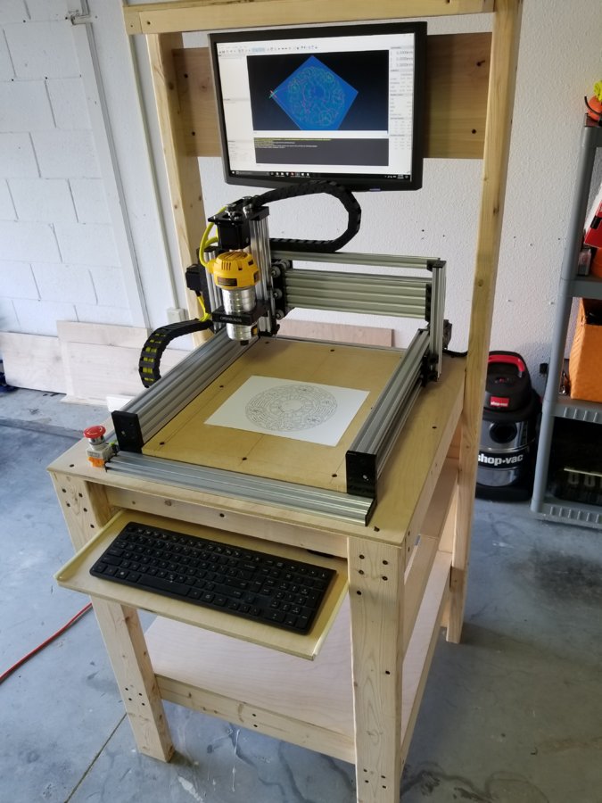
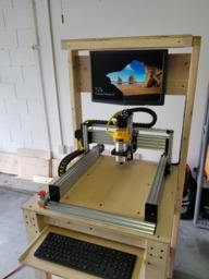
Time to move this outside so we can cut some stuff! I started just building a table, but I decided to add a monitor mount and top shelf.
Placing the CNC on the table to test the fit.
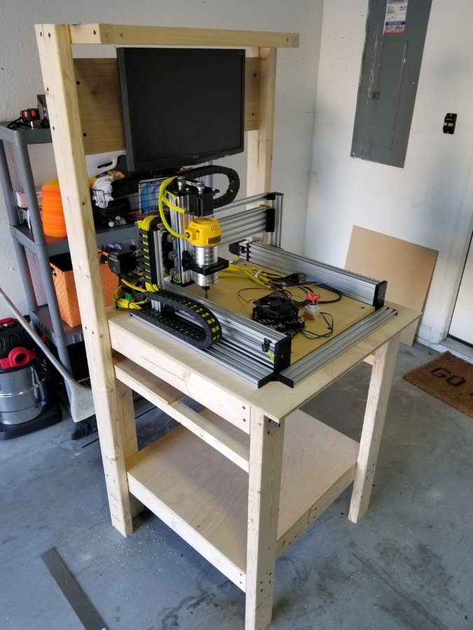
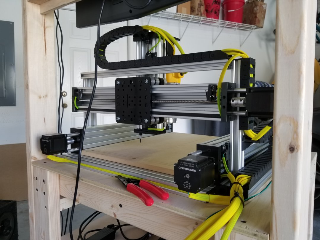
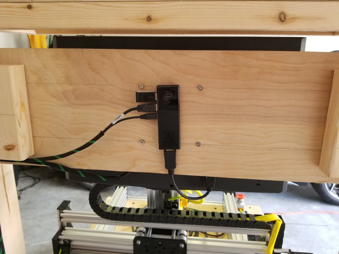
Starting to clean up the wiring, Intel Compute Stick mounted behind the monitor mount.
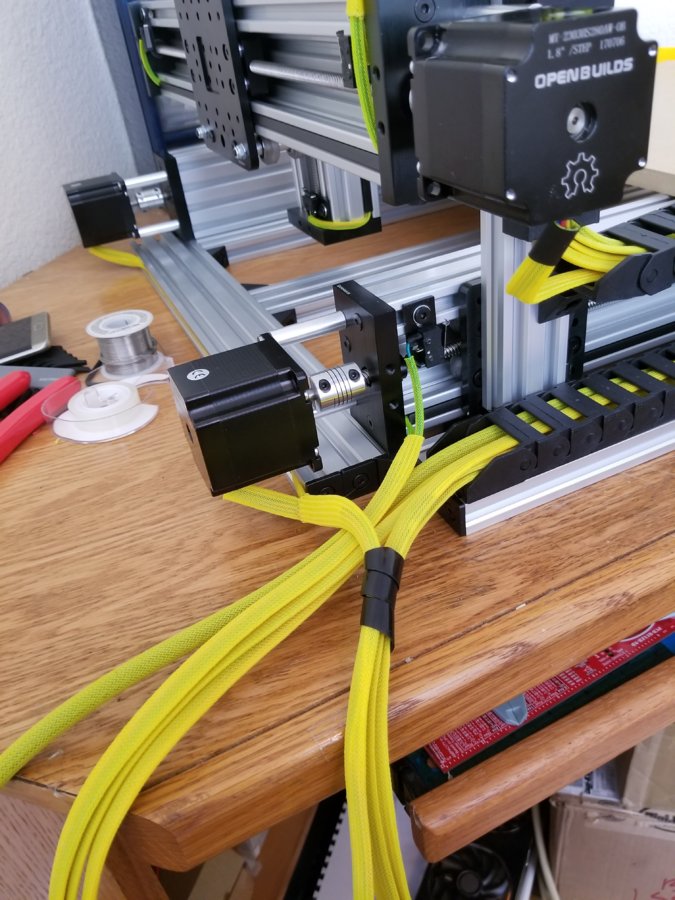
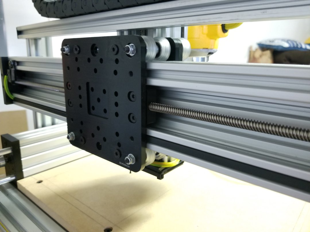
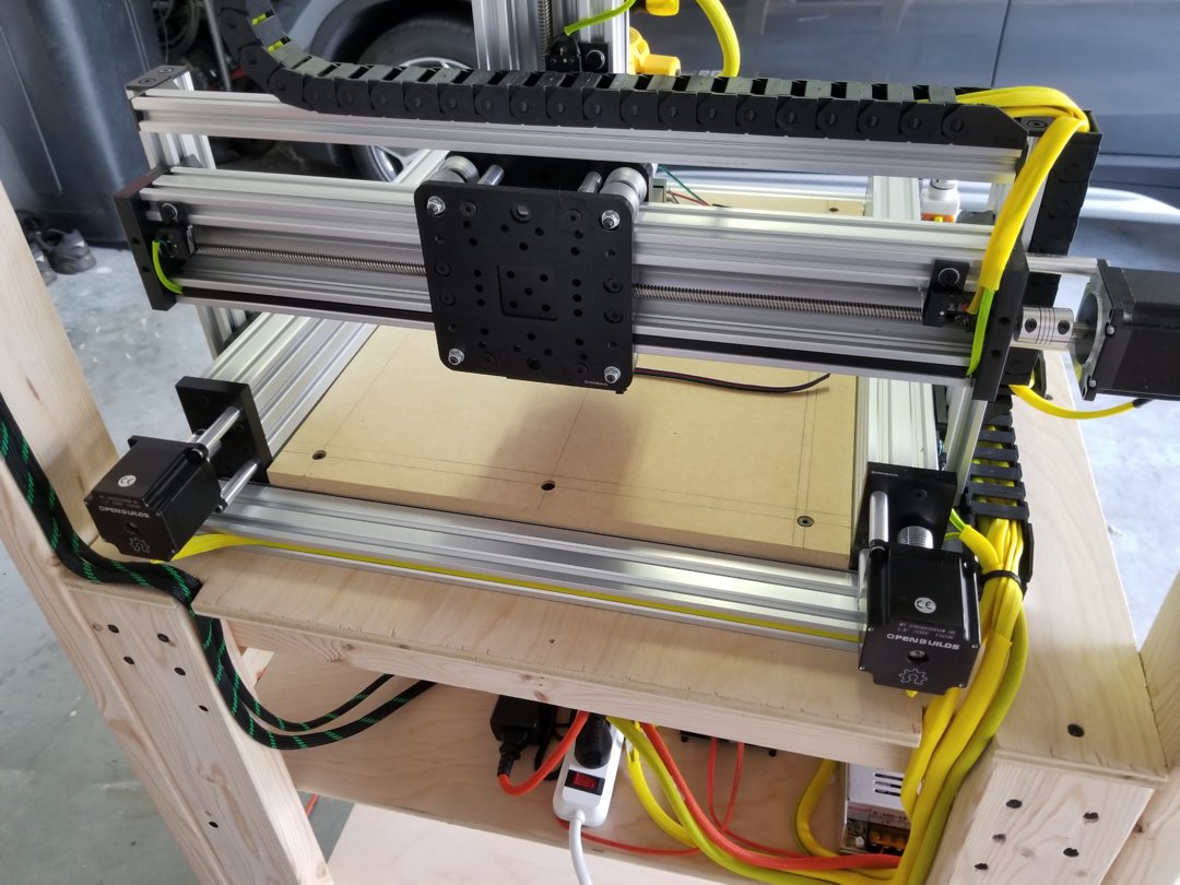
X-axis gantry detail
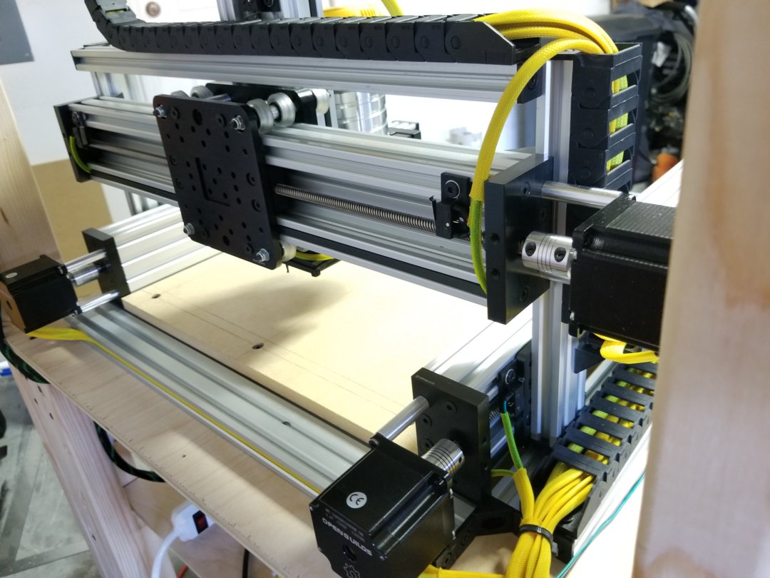
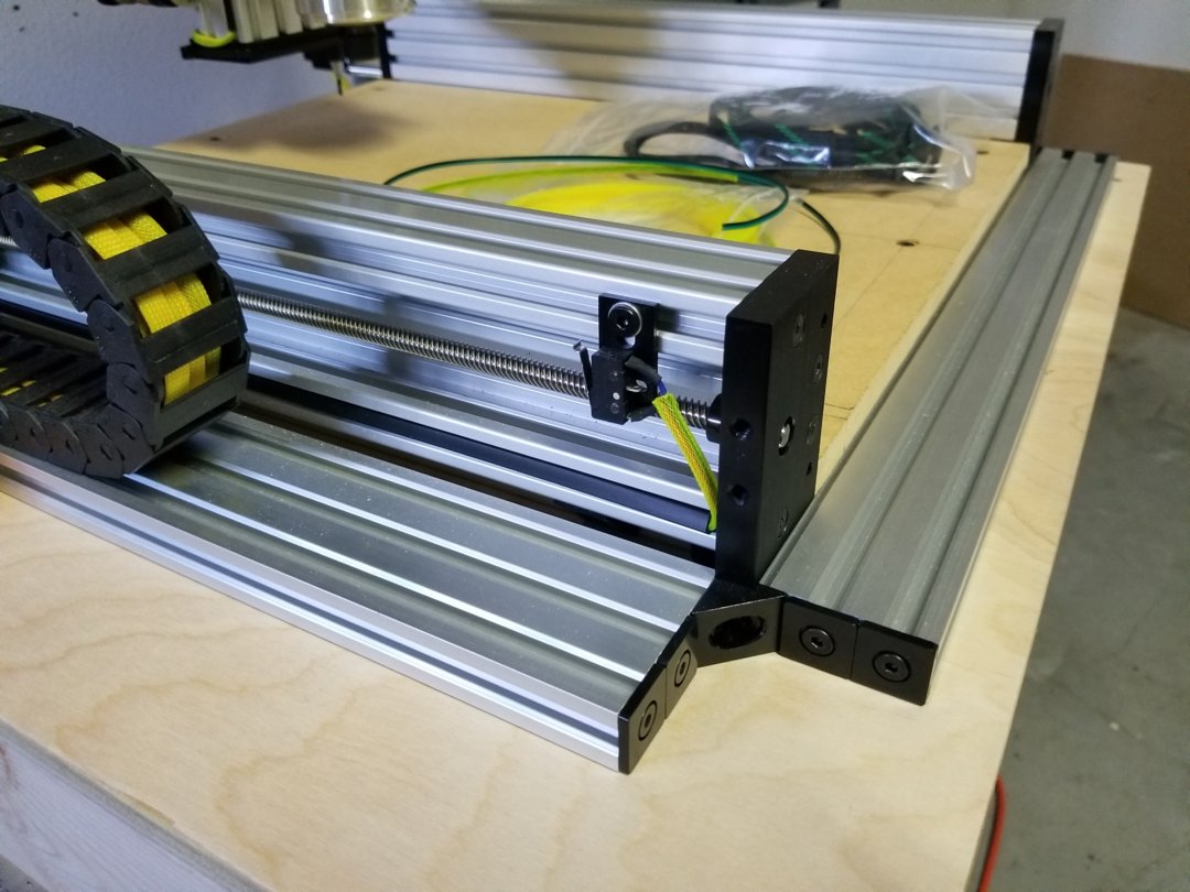
Y-axis limit switches and wire exit detail
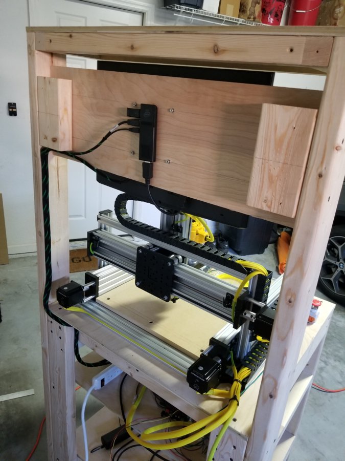
Riser detail
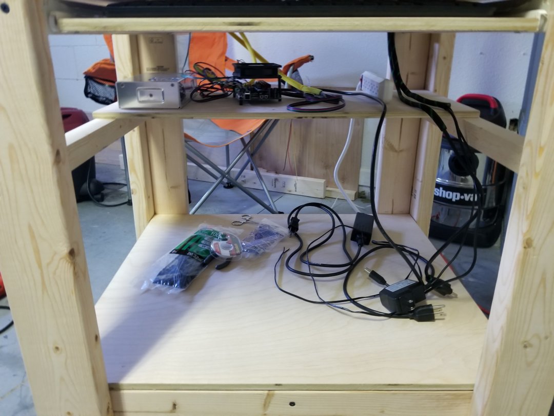
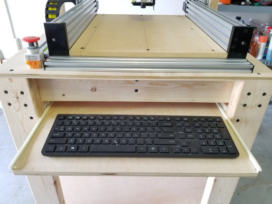
I decided to add a pull out drawer for a keyboard.
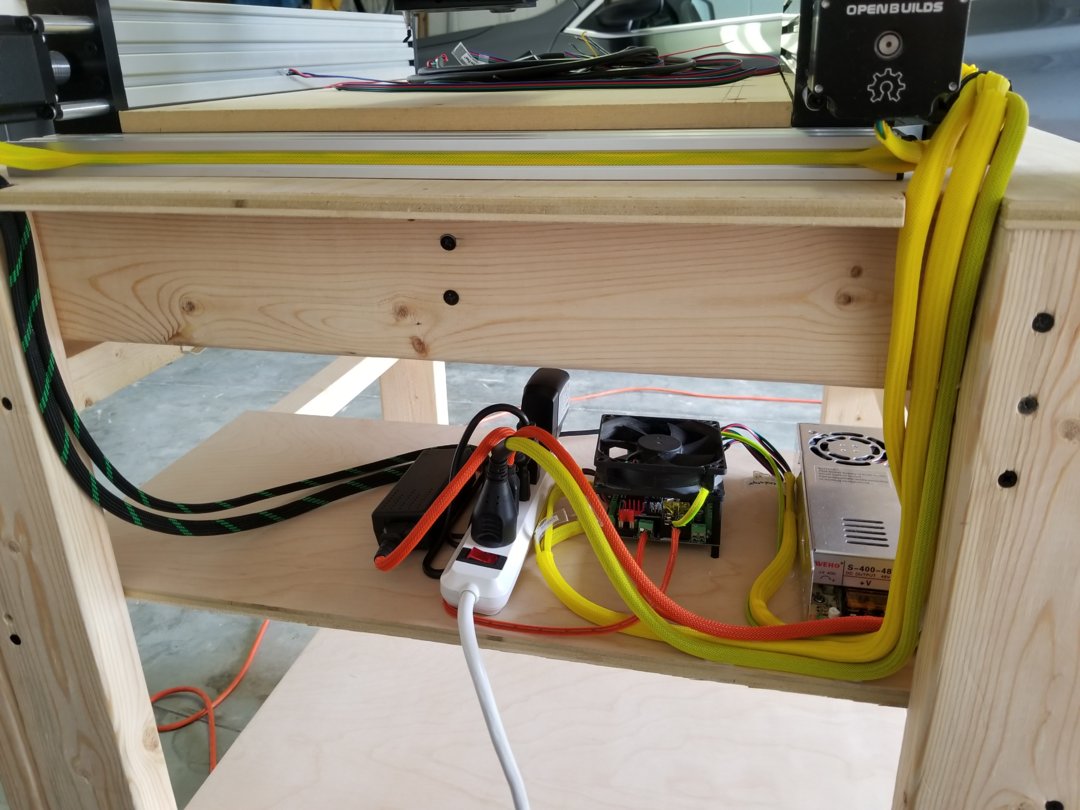
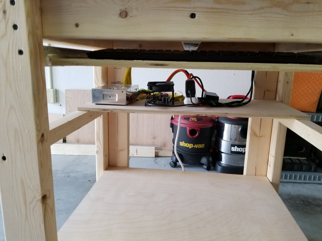
Lower shelf for the electronics
All wired!

A test drawing to check everything still works after all the wires had been shortened to length.
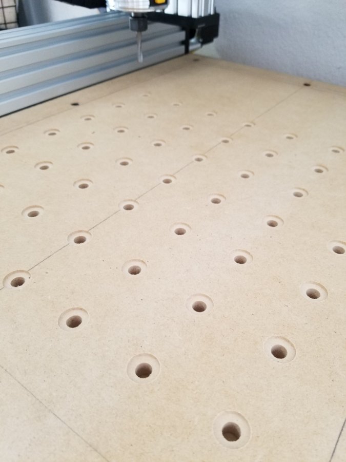
First cutting operation! Preparing the spoiler board for nuts.
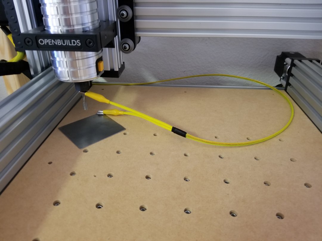
Z-probe made from 22GA steel sheet from HomeDepot, seems to work very well and is very flat with a consistent thickness. Amazingly, I am only seeing a 0.1mm drop back to front, and 0.1mm left to right without bed leveling enabled.
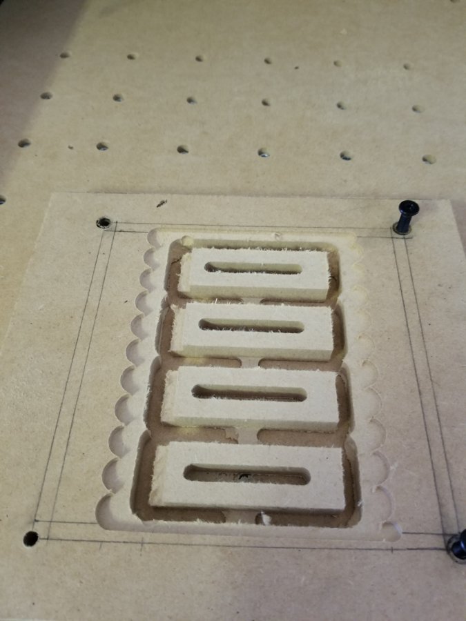
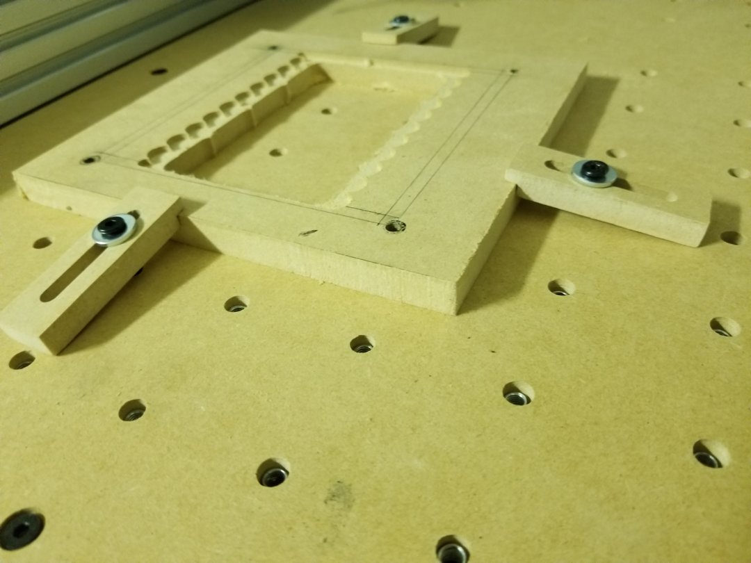
Designed some work hold downs in Fusion 360 to try learn more about the CAD and CAM process there. They turned out really nice, but haven’t used them yet. Tolerances were +0.01 to +0.03 over actual modeled dimensions, I can live with that!
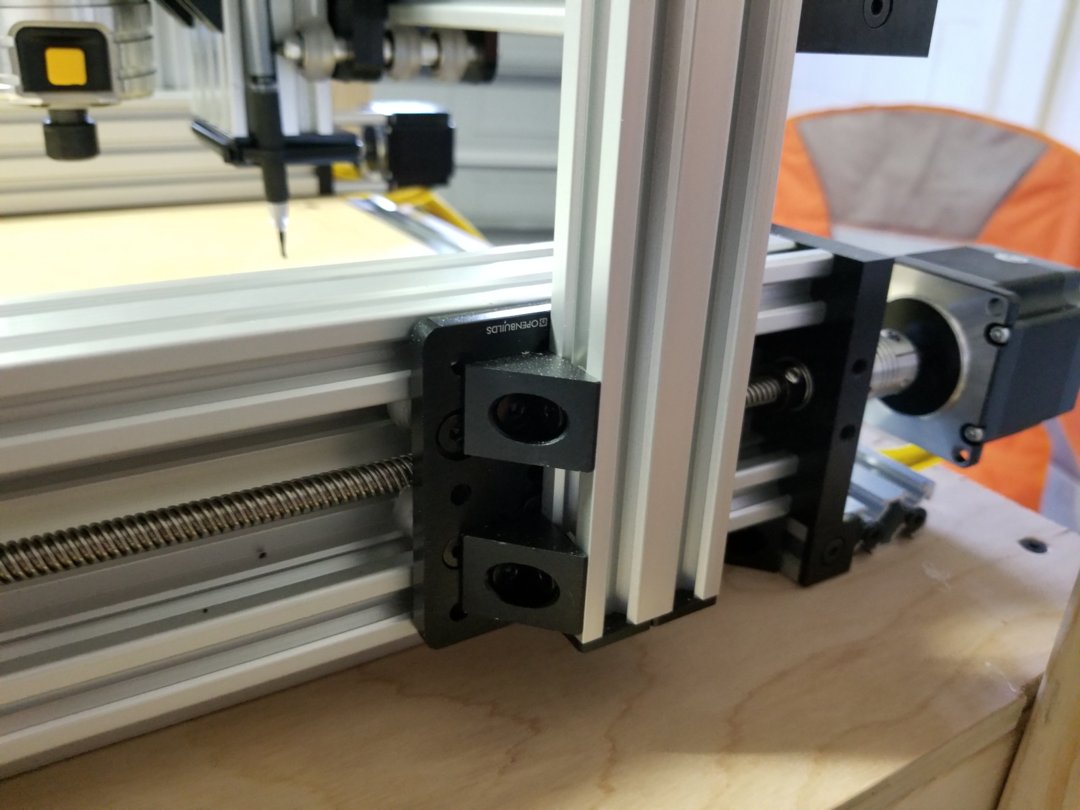
My biggest concern with OTiS was not using machined riser plates. I wasn’t sure this design of X-axis attachment to 20x40x250mm V-slot beams was feasible. So far, it looks good. There is very little flex or torsion in the actuators.
Parts list and SketchUp model attached, and please let know any questions! I have learned so much during this build and it wouldn’t have been possible without OpenBuilds and the community around it. Thanks!
OTiS 500mm
Build in 'Cartesian Style CNC' published by jz321, Feb 28, 2018.
OTiS (Off The Shelf) is 500mm cartesian CNC that can be built with all off the shelf parts from OpenBuildsStore. It features C-Beam actuators and a V-Slot frame.
-
-
Build Author jz321, Find all builds by jz321
-
- Loading...
-
Build Details
- Build License:
-
- CC - Attribution - CC BY
Reason for this Build
I have a passion for building/making.Inspired by
Kyo Sphinx -
Attached Files:
Parts list
Qty Part Name Part Link Comments 1 See attached file Link -
Attached Files: