
This build is an add-on for any kind of CNC machine, 3D printer, laser cutter, etc. Optical endstops are an extremely inexpensive way to accurize your machine while providing a safety override to protect the machine from errors that could damage it.
Cost: You can find these on ebay for as little as $2.57 ea and you need 3 for a grand total of $7.71. This includes the resistors and LED as well as the PCB all mounted and ready to plug into a connector. I got mine from a teardown of an old Laserjet printer for free so I had to make the circuit myself.
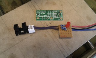
Making the circuit: I used the Reprap generation 7 electronics schematic and a protoboard to get things working and I will later on mill a pcb. One of the advantages of making a custom PCB is you can shield it and all the wires plus put it next to the computer used to operate the device and see which axis hit the limit. There's the schematic attached and here's a video of my protoboard with explanations of the pinouts.
Mounting the switches: I used liquid nails and glued them directly onto the frame for the x axis. You want to mount them on the moving part where the wheels+motor are mounted. Then you put a piece of material at the ends of the rail which trip the switch when it gets to that end of the rail. On the y axis I used a piece of cardboard to mount the switch and then mounted the cardboard with electrical tape. Don't laugh, it works. On the z axis I fabricated a piece of metal which screws onto the threaded rod plate and then glued the sensor to the metal. Here's a video of the mounts:
Configuring the software: This will depend on your motor controller and software. Most motor controllers have 4 input pins for limit switches. You'll use 1 input for each sensor. This input is usually +5V and when it gets shorted to ground(0V) it trips the limit switch. After you wire the sensor to the input, you just tell the software that this is your home+both limits(Max and Min). The software can figure out which is which. The setup is basically identical to mechanical switches.
Optical Limit + Home Switches
Build in 'Circuit - Software Project' published by The Dude, Feb 8, 2014.
Optical home and limit switches for cnc, 3D printers, laser cutters, etc.
-
-
Build Author The Dude, Find all builds by The Dude
-
- Loading...
-
Build Details
- Build License:
-
- CC - Attribution Share Alike - CC BY SA
Reason for this Build
I built this because I l need the precision of optical home switches so that I can create a platform for pick-and-place, cnc, 3D printing, laser cutting, drag-knifing, etc.Inspired by
Reprap -
Attached Files: