
This is a design I've had in my "spare parts bin" for two years. I do not remember where I saw the layout, and the image for it was named Unnamed-mechanism.jpg (shown below). If anyone recognizes the mechanism and has a name for it, and an author, please let me know. Until, or unless, I'm calling it "OpenXY".
I hope to begin construction after the first of the year. Since the "Unnamed-mechanism" design is unusual I thought I'd try getting some feedback before getting out the saw ("measure twice/cut once" theory).
OpenXY combines the main feature of a CoreXY (X & Y motors are stationary) but uses the simple Cartesian algorithm for moving the X & Y axis (reducing calculation overhead for the controller). One motor independently runs the X axis while the other one independently runs the Y axis. While the design uses more belting and idlers than a CoreXY, the design is easy to "square", stablize, and calibrate.
This design also borrows inspiration from our fellow maker Josh.Pierce's CoreXY W/ Fixed Build Plate & Enclosure. The simple elegance of Josh's stationary build bed with an X/Y frame moving up the Z axis was just toooo seductive to pass up.
Assembly SKP is in the Files tab.
The Unnamed-mechanism:
![[IMG]](proxy.php?image=http%3A%2F%2F3dwrx.com%2Fopenbuilds%2FOpenXY%2FUnnamed-mechanism.jpg&hash=833f7680a08c5ea633693d10dc7ca30d)
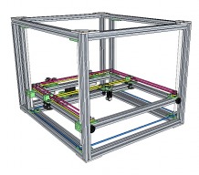
Four images of the assembly with different views.
The design could be for any size build, this one is for a 12 inch square build. The three axis motors are confined to a 60mm deep area on the back of the printer which has room for mounting a PSU and controller above the Z axis motor. As such the printer could be easily enclosed with acrylic panels. The design assumes a bowden type extruder not included in the SKP. Also not included is the build plate and it's mounting braces. The design envisions using the OpenBuilds hidden brackets for binding the outer frame and X/Y frame extrusion pieces.
![[IMG]](proxy.php?image=http%3A%2F%2F3dwrx.com%2Fopenbuilds%2FOpenXY%2Fassembly-1.jpg&hash=20490d2d61e3599a796fbd991179b4ef)
![[IMG]](proxy.php?image=http%3A%2F%2F3dwrx.com%2Fopenbuilds%2FOpenXY%2Fassembly-2.jpg&hash=4974c180f683de633ca889a418d37dd8)
![[IMG]](proxy.php?image=http%3A%2F%2F3dwrx.com%2Fopenbuilds%2FOpenXY%2Fassembly-3.jpg&hash=46cd9dcdea30588bcfcdcc0e4724c50f)
![[IMG]](proxy.php?image=http%3A%2F%2F3dwrx.com%2Fopenbuilds%2FOpenXY%2Fassembly-4.jpg&hash=888a34aaf5122157e90f4d49153cb273)
Images of each axis.
X Axis
![[IMG]](proxy.php?image=http%3A%2F%2F3dwrx.com%2Fopenbuilds%2FOpenXY%2Fassembly-x.jpg&hash=4c24e6c451206b30ad0ebde6e0a6319b)
Y Axis
Z Axis
I plan on using 8mm threaded rod for the Z axis. The 4 pulleys mounted on the rods will be 20 tooth. The pulley on the Z axis motor will be 16 tooth. That gives a 5:4 ratio. An 8mm threaded rod moves 1.25mm per revolution. (1.25mm/5) * 4 = 1mm, so one revolution (200 steps) of the motor = 1mm movement. Hence, each motor step will produce a 0.05mm layer movement, guaranteeing that layer height (in 0.05mm increments) will always move by full steps eliminating the microstepping problem for Z axis. I've experienced one caveat to this concept - the #define DISABLE_Z true in Marlin has to be changed to false to eliminate the jump from energizing the Z axis motor between moves.
OpenXY
Build in 'H-Bot and Core XY' published by Keith Davis, Nov 30, 2015.
Combines the layout factor of a CoreXY while using Cartesian logic. The design has a fixed build plate - moving an X/Y frame on the Z axis enclosed by an outer main frame.
-
-
Build Author Keith Davis, Find all builds by Keith Davis
-
- Loading...
-
Build Details
- Build License:
-
- CC - Attribution NonCommercial - Share Alike - CC BY NC SA
Reason for this Build
I'm snowed in and it's Sunday - reason enough....Inspired by
-
Attached Files:
![[IMG]](proxy.php?image=http%3A%2F%2F3dwrx.com%2Fopenbuilds%2FOpenXY%2Fassembly-y.jpg&hash=c826ec6ed3cd5baf9a44716eec7c191f)
![[IMG]](proxy.php?image=http%3A%2F%2F3dwrx.com%2Fopenbuilds%2FOpenXY%2Fassembly-z.jpg&hash=dc321ca138cac685f012433324a2e2de)