Open source large format CNC-machine & 3d-Printer
For a schoolproject we decided to build this CNC-machine.
For those, wanting to view the files (with a PDF-Version of this text) on Github, here´s the link: Sebastian-Schuetz/OPEN-SOURCE-LARGE-FORMAT-CNC-MACHINE-3D-PRINTER
In the Github-Repo you can find the Documentation and CAD files for a large format CNC-machine we build with OpenBuilds parts.
The total size of the machine is roughly:
Team
- X: 172 cm
- Y: 172 cm
- Z: 128 cm and weights around 200 kg.
- David Koch
- Sebastian Schütz
- Stefan Schütz
For further information you should take a look in the CNC-OpenBuilds.pdf file!
Filestructure:
- Bilder: contains (additional) pictures to those in the pdf
- CAD-files: contains CAD-files (who would have thought). Furthermore you can check out the online model here: A360
- Motormounts-dxf: The 3D-DXF files for the motor mounts, so that you don´t have to extract them form the CAD-model for milling
- Aufbauanleitung.pdf: Contains the "manual" on how to build the CNC. For reference always stick to the CAD.
- CNC-Mill-v3_Render.jpg: A high quality render of the finished machine
- CNC-OpenBuilds.pdf: THE MOST IMPORTANT DOCUMENT. It provides you with further information on the design decisions, ...
- SLP...: The circuit diagram. IT IS 28 PAGES. And was done professionaly. So if you think about building a CNC-machine and want to do it right, this is a great starting point.
- Materialliste.xlsx: The partlist with BOM
Description:
Content
1. Introduction. 2
2. General information. 2
3. Design choices. 4
3.1 Power. 4
3.2 Open Build V-wheels. 4
3.3 Motors with Trapezoidal Screws. 4
3.4 Controller board. 5
3.5 Spindle. 7
3.6 Motor mounts. 8
3.7 Overall design. 9
4. Plans. 9
4.1 CAD-Design. 9
4.2 Wiring Diagram.. 10
4.3 BOM... 12
4.4 Manual and Instructions (kind of). 13
5. Construction. 13
5.1 Modification of the spindle. 13
5.2 Machining of the custom parts. 13
6. Issues. 15
6.1 Z-Axis bending forward. 15
6.2 X-Axis not moving. 15
6.3 Problems during the construction. 15
7. Update I 16
1. Introduction
On our school “Birklehof” in Germany, we were offered the possibility to submit a project to the program “Micro-Maro-Mint” of the “Baden-Württemberg-Stiftung” (Baden-Wuerttemberg-Foundation). The “Micro-Macro-Mint”-program supports students interested in mathematics, informatic or engineering with up to 2500€ for their projects. After submitting our application with a first 3D-Model and a Bill of material, we got the funding.
Our goal was to build a large format CNC-machine, with the money available. Due to limited access to a machine shop, we had to rely mostly on screwed connections. This led to the design decision of using aluminium extrusions. The Open Build rails seemed like a perfect fit for our project.
Furthermore we added the option to use the machine as a giant 3D-printer. The wires for the extruder, a stepper motor driver and a sufficient power supply are already installed in the electrical cabinet.
To make this project as open source as possible we used the open builds platform and an Arduino Due with TinyG2 core as controller.
2. General information
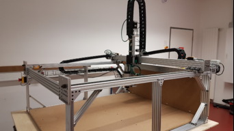
The current state of the machine (without the additional Y-axis):
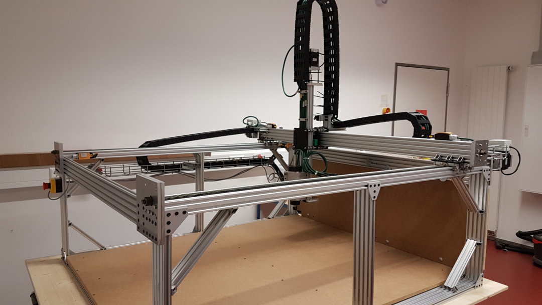
The final form:

The current version isn´t behaving according to plan, so we had to do some design tweaks, which should solve these problems. In the section Issues we will talk about those.
The total size of the machine is roughly:
- X: 172 cm
- Y: 172 cm
- Z: 128 cm
- This measurements are measured up to the outer most endpoints. For reference, the MDF-plate on the bottom of the machine measures 150 cm by 125cm. The cable chains are not taken into account
The milling area boils down to:
- X: 116,8 cm
- Y: 112,5cm
- Z: 16,5 cm
While maintaining a weight of ca. 200 kg.
3. Design choices
3.1 Power
A detailed description can be found under Wiring Diagram. First things first. We chose to use three phase power. This is wildly available in Germany, so there should be no problems. We did this, because the maximum power output from a normal single phase outlet is about 230V at 16 Amps, which gives you roughly 3680 watts. Considering the four 350 Watt power bricks for the stepper motors and the 1,5 kW spindle, this could get us pretty close to the limit. So we split the main parts over the three phases. On for the spindle, one for the stepper motors and one for the controller and the 3D-printing part. This is also helping to reduce interferences.
3.2 Open Build V-wheels
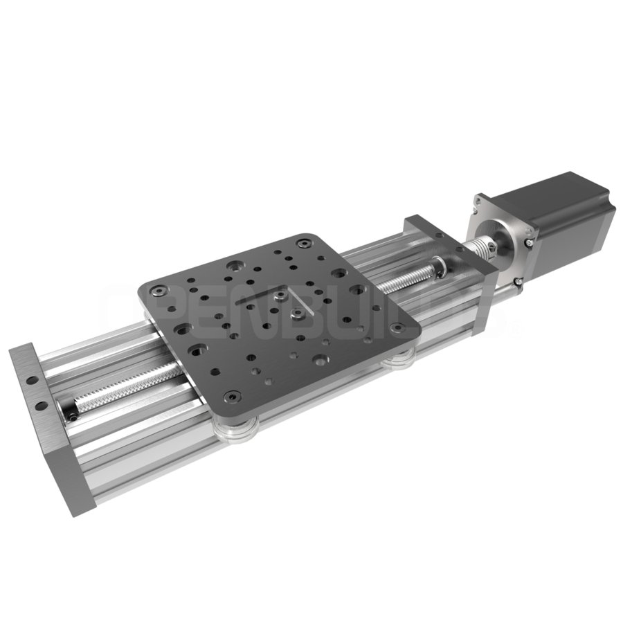
Figure 3: Design template
Our goal was to drive costs down, which was the reason, why we decided to use the V-wheels. Furthermore the lack of a proper machine shop forces us to rely on as many screwed connections as possible, so aluminium extrusions with an integrated linear rail system just came in handy.
The design for the x-axis was borrowed form the linear actuators in the open build store. But the load on the wheels in this design is too high, so the won´t turn properly. In the rendering of the final version you can see, that we decided to add an additional Y-axis to spread the load onto more wheels.
Figure 3: C-Beam® XLarge Linear Actuator Bundle
3.3 Motors with Trapezoidal Screws
The stepper motors are NEMA 34 stepper motors with 1232OZ/IN and the 5.6A DM860A drivers. We bought one of these 4 Axis-kits out of china and are quite happy with it. The motors are mounted to our custom motor mounts and are connected to the trapezoidal screws with a normal 12 to 14 mm coupler. The used trapezoidal screws are 12 mm in diameter and have a pitch of 3mm. We decided to use these, because we couldn´t get any ball screws in the desired length with this diameter. The main problem was, that all nuts for screws over 12 mm in diameter were to big to be used inside the C-beams.
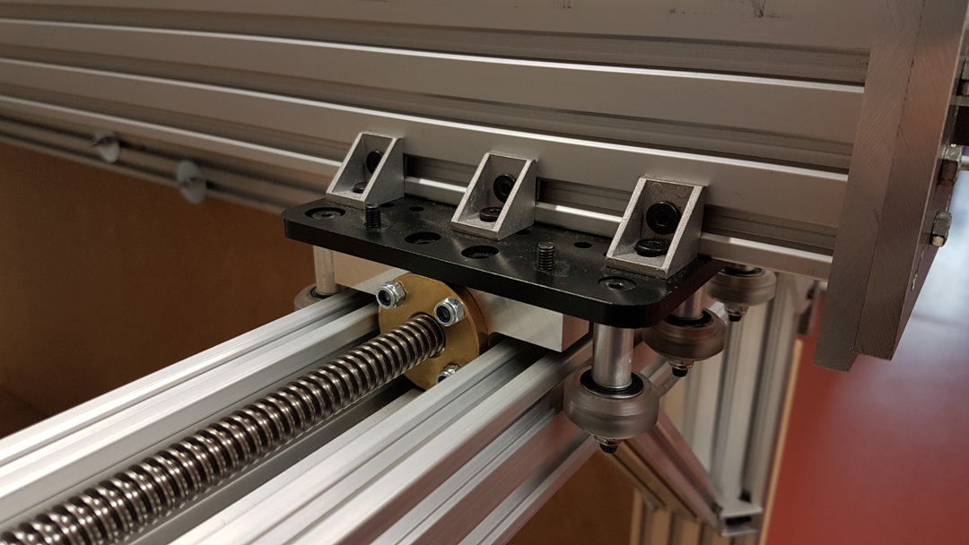
Figure 4: The holder for the nuts
As you can see in picture four, the space inside the C-beam is filled out by the holder for the nut. The holder was machined on our modified Esel EP 1090 (it now runs on grbl). So 12mm was the maximum we could pack into a c-beam. In hindsight we probably should have used ACME-Screws with the same diameter.
The motor current on the drivers is set to the maximum of 7,8 Amps
1 2 3
OFF OFF OFF
and Microstepping is set to 2.
5 6 7 8
ON ON ON ON
3.4 Controller board
The machine is running of TinyG2core version 101. It runs on an Arduino due. All outputs and inputs of the Due are protected via Optocouplers. These furthermore serve as level shifters. The connections are all following the wiring suggested on the official wiki page of tinyG2 and can also be found in the Wiring Diagram. Due to the sad fact, that the Due doesn´t have an EEPROM, we have to send all commands on every startup. Here is the list of the current configuration:
$ej=0 //Enable text mode
$1mi=2 //Microstepping: 2
$2mi=2
$3mi=2
$1tr=3 //Travel per Revolution: 3mm
$2tr=3
$3tr=3
$lim=1// activate limit switches
$di1mo=1 // Xmin limit switch activated. Set to active hi (NC)
$di1ac=1 // Stop when hit
$di1fn=1 // Use as limit switch
$di2mo=1 ; Xmax
$di2ac=1
$di2fn=1
$di3mo=1 ; Ymin
$di3ac=1
$di3fn=1
$di4mo=1 ; Ymax
$di4ac=1
$di4fn=1
$di5mo=2 ; Zmin - disabled
$di5ac=0
$di5fn=0
$di6mo=1 ; Zmax
$di6ac=1
$di6fn=1
$xsv=500 // 500mm/min homing speed
$ysv=500
$zsv=500
$xtm=1168 //Max travel X-axis
$ytm=1125
$ztm=165
We are running it with CNCjs and had no problems till now. Every command entered will be validated. We use the left USB-Port on the DUE and it will show up as a Microsoft Serial USB-device.
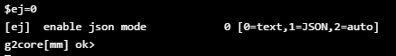
Figure 5: Example of a valid command
3.5 Spindle
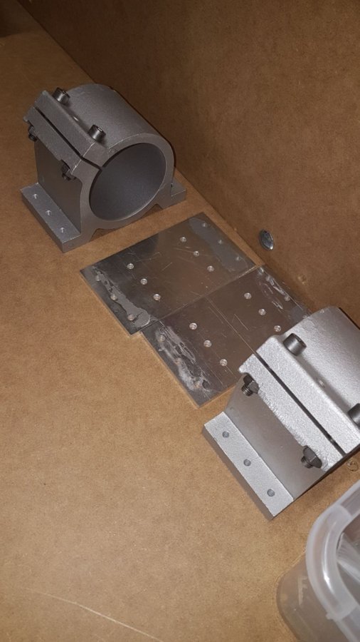
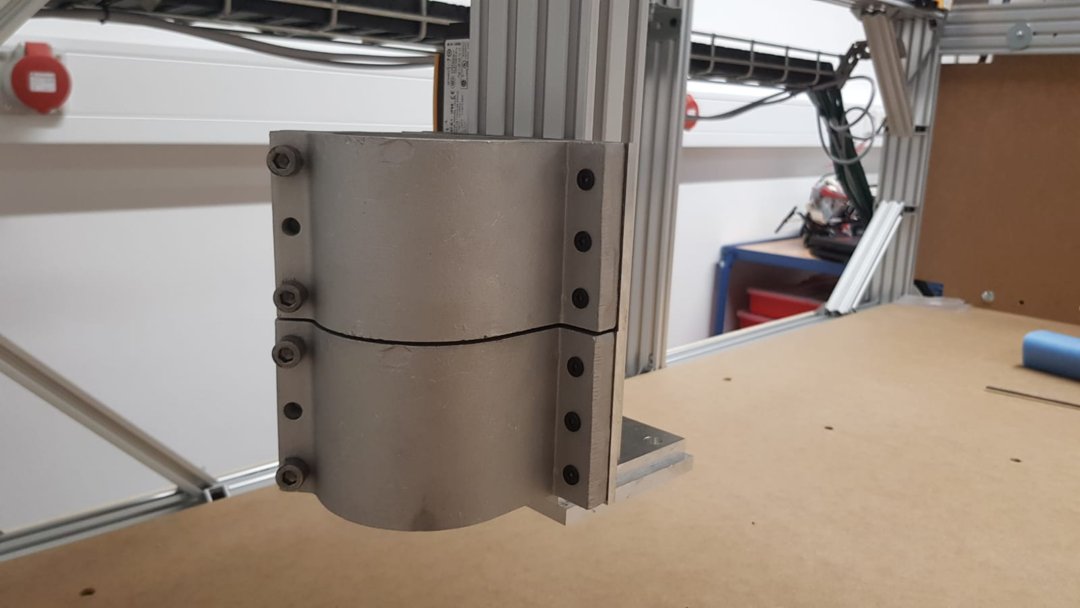
Figure 6: Spindlemount with adapter plates
We use a 1,5 kW china spindle for milling. It is air-cooled and running of a Variable-frequency drive. This allows for a smooth speed control. In comparison to a router (e.g. the typical DeWalt one), it was also easier for us to mount and is pushing more power. The mounts for the spindle had to be bolted to adapter plates we made from 5mm aluminium. There is no plan for these, because it was just some holes. The modification of the plug for the spindle an extra part.
3.6 Motor mounts
The motor mounts are custom designed and machined. We made them on our modified ESEL EP 1090 (running of GRBL).
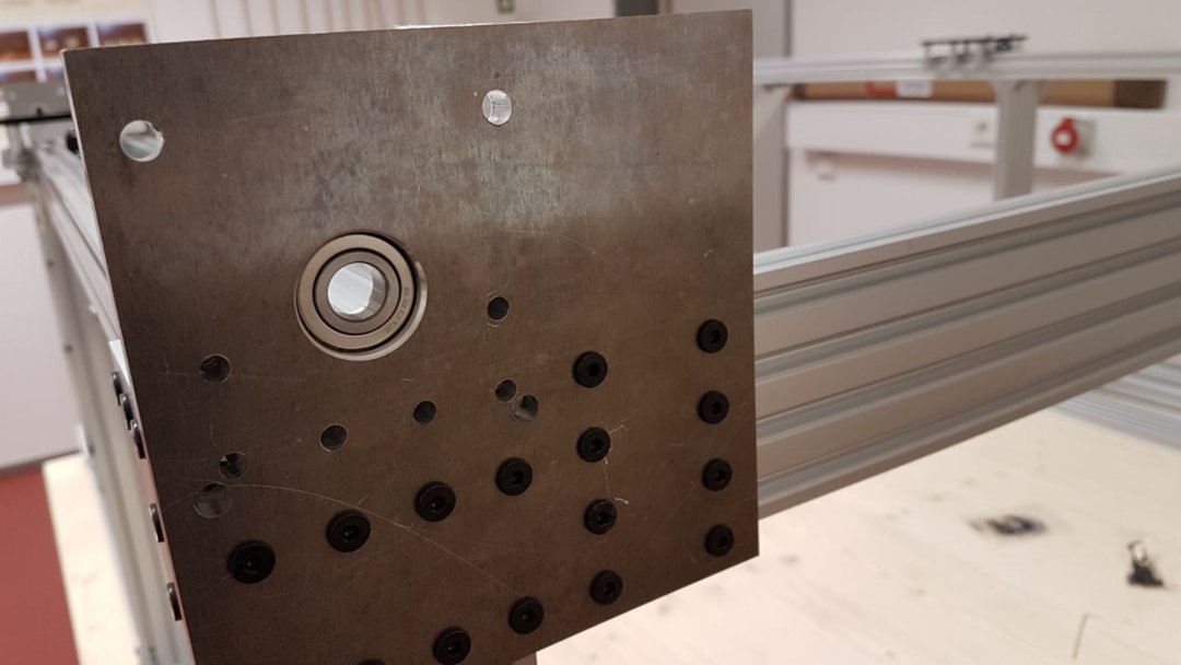
Figure 8: The motor mount without motor
As you can see in the picture they actually serve three purposes:
1. They are connecting elements in the frame
2. The bearings take axial load out form the trapezoidal screw, so that it doesn’t destroys the bearings in the motor. In hindsight we learned from a “This Old Tony”-video[1], that there exist tapered roller bearings, which would have been the better choice here.
3.
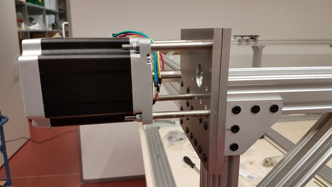
Figure 9: The motor mounted with the stainless steel tubes
They hold the motors. The motors are mounted with a 5mm threaded rod inside a stainless steel tube.
This design allowed us to cheat a little bit and saved us the headache of machining a fitting faceplate for the motor. One additional improvement apart from the tapered roller bearings would be to put a screw through the top part of the motor mount. In the picture is seems like the two aluminium plates would be separating, but in reality it is not as bad.
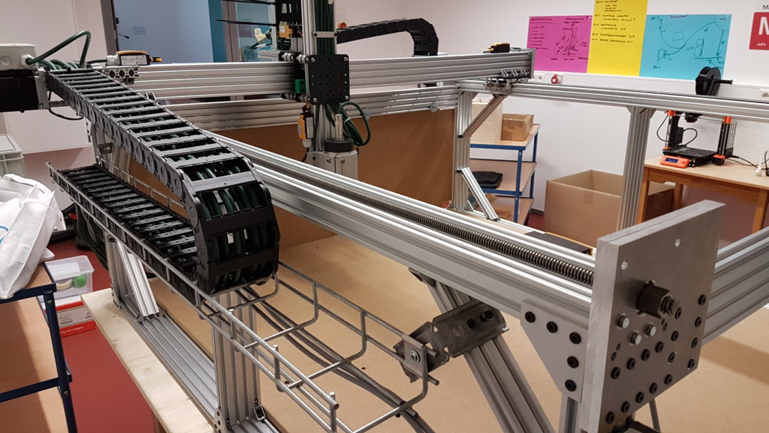
Figure 10: attachment of the TR12-3 screw
The bearings take the axial load, because we bought nuts for the trapezoidal screw, took one side drilled a small hole and cut a thread for M3 grub screws. The nuts sit one both sides of the bearing and also on the end, where the motor is mounted.
3.7 Overall design
We went with a cage like design and till now, it has served as well. We were able to get a surprising amount of precision with the aluminium extrusions. The deviation on the X-Rails is mostly down to measurement errors. The added MDF plates add an additionally stability, especially the backplate, and serve as a waste board.
4. Plans
4.1 CAD-Design
The design was done in Fusion 360. I exported the model to every format, the export window offered, so that there are no problems with different CAD solutions. Furthermore here is the link, you can use to download the model from Autodesk: A360 This should give you the most current version.
4.2 Wiring Diagram
The electrical part of the machine is complying with the following regulations:
- 2006-42-EG Maschinenrichtlinie
- BGI5003 Maschinen der Zerspannung
- DIN EN 60204 Elektrische Ausrüstung von Maschinen
Here we got some support form the father of Stefan and Sebastian. The whole construction was done in ePlan P8.
The controls consist of two thermostat controlled ventilated electrical cabinets. One for the Variable-frequency drive of the spindle and one for the actual controls. In the second one are the power supplies, the drivers for the stepper motors, the power supply for the extruder and the Arduino DUE. The USB-port of the DUE is expanded to outside of the cabinet, so that the machine can be run with the cabinets closed.
The extra cabinet for the variable-frequency drive was done due to EMC reasons, so that it wouldn´t interfere with the low voltage signals from the Arduino. The parameters for the variable-frequency drive were taken from this very useful site: RC Hobby - CNC, NC, Fräsen, Fraese, PIC, Microchip, digital Caliper, digital Meßschieber, Gauge, Interface, Flugmodellbau, Simulatoren, Software, Modelle, MotorenClancy Aviation, Schulze, Lader ISL 6-430
The cables and the cable chains were provided by Igus[2]. The used cables are mostly shielded and are designed to be used inside cable chains.
All end positions on the X, Y, and Z-axis are equipped with safety limit switches (Normally closed), which are galvanic isolated through optocouplers, before the signals are interpreted by the Arduino DUE. In order to make the limit switches more resistant to interferences we are using a 12V signal instead of the 3,3V signal which would normally be provided by the Arduino.
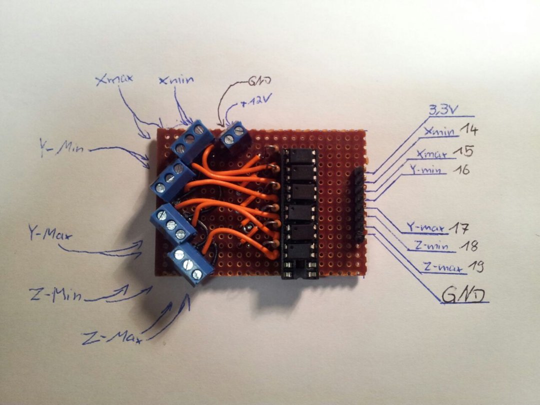
Figure 11: The optocoupler circuit board
The CNC is equipped with two emergency stops, which isolate the machine from main voltage. The Arduino and the optocoupler board are the only ones, which are still provided with their 12V power. There is an additional off-switch, which turns off the machine completely.
The controls for the machine are in the door of the electrical cabinet.
On the larger cabinet are:
- On/Off
- Spindle on/off
- Extruder on/off
- Emergency stop
- Off-Switch
And the smaller on:
- Speed
- Clockwise/0/anti-clockwise rotation
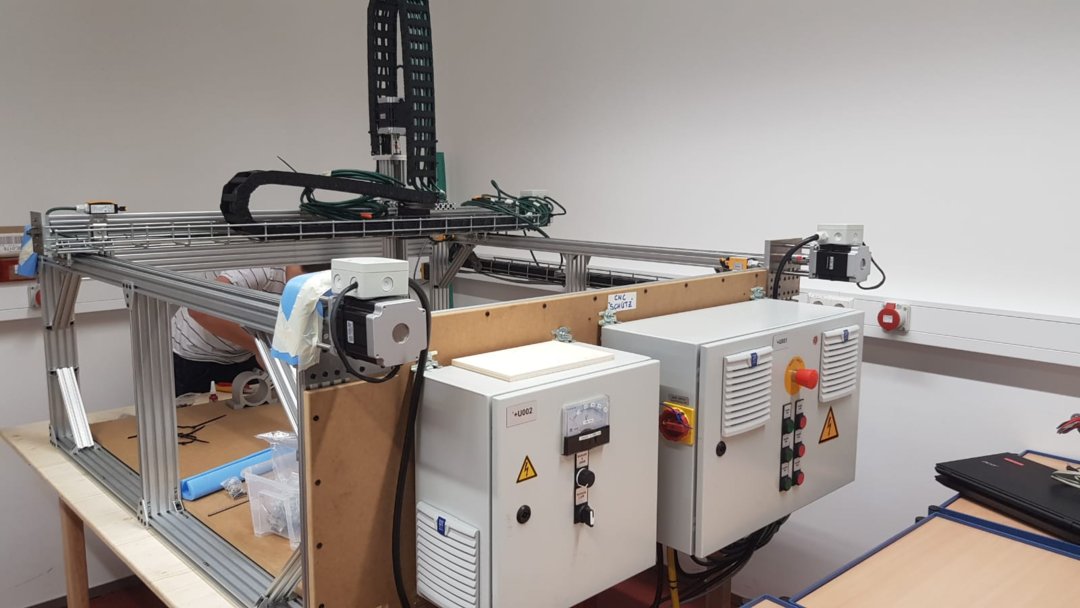
Figure 12: The controls for one/off, ...
The speed control is done with a 10kΩ potentiometer and a 0-10V analog display, where 10V equals 24000 rpm.
After completion the machine was tested according to the regulations by an electrical engineer.
4.3 BOM
The current BOM states 2.308,35 €. In this calculation are not included:
- The wooden plates on the back and the bottom of the machine
- The COMPLETE wiring, because we were sponsored (~1000€. You could cut the price by using cheaper hardware/no-name electronics):
o Cable cabinets
o Wiring for the cable chains
o Cable chains with fitting mounts
o Small electric parts (switches, relays, etc. what goes into the electrical cabinet)
- An optional glass bed for using the machine as a 3D-printer
The nuts we used to connect the trapezoidal screw with the C-beam gantry plate also went up significantly in price. We had some with 4 holes in them, but can´t find them anymore. The measurements for our nuts are:

Figure 13: The used nuts. [mm]
4.4 Manual and Instructions (kind of)
The document “Aufbauanleitung.pdf” contains pictures from the CAD-Model and some tips, how you could build the CNC. Just to be clear: This isn´t a perfect manual. For example we never added mounts for the cable chains and improvised them. So you should feel comfortable doing such a big project. For reference: The mechanical construction alone took over 100h man-hours. The wiring inside the electrical cabinets plus laying the cables inside the cable chains and hooking them up to their destinations took approximal another 60h. So this is not a weekend project.
5. Construction
5.1 Modification of the spindle
Due to using the inside the maker scene popular china spindle, we realised that the motor is equipped with a CE-certification, but the used 4-pole plug didn´t have a ground wire connected to the metal frame. Furthermore, could be assumed that the used plug only was suitable for low-voltage applications (~60V). To solve these problems, we added a ground connection to the metal frame and changed the plug to a sufficient M17-high power plug rated for 690V at 23A.
The rpm can be controlled between 4000 and 24000 rmp.
5.2 Machining of the custom parts
We had two custom parts. One there the motor mounts and the other was the holder for the nuts. We machined both on our ISEL EP1090 with a 6mm and 3mm bit out of aluminium.
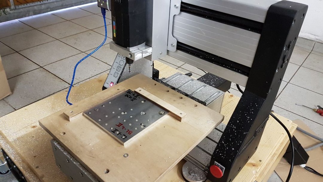
Figure 14: Preparation for machining
We had to machine 16 aluminium plates, but we designed the mounts in a way, so that we only needed 8 files and could use them twice:
- 2x Motormount hinten I (links)
- 2x Motormount hinten II (links)
- 2x Motormount hinten I (rechts)
- 2x Motormount hinten II (rechts)
- 2x Motormount I (Y)
- 2x Motormount II (Y)
- 2x Motormount I (Z)
- 2x Motormount II (Z)
All those files are added. They are 3D-DXFs. If they don´t work for you, you can still take the mounts from the 3D model.
Always two plates of the motor mount go together and sandwich on of the bearings in between them.
The holder for the nuts war pretty simple. The hole connecting the holder to the C-beam gantry plate was drilled by hand.
6. Issues
6.1 Z-Axis bending forward
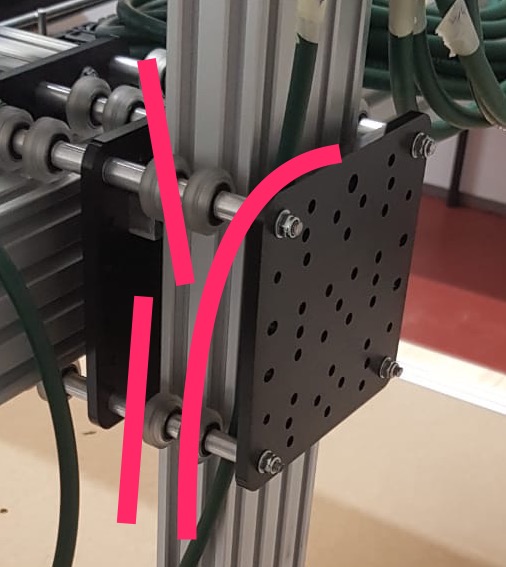
Figure 15: The Z-axis is bending the rods
As someone is might able to see in the picture, the Z-axis is too heavy. It is bending the 5mm rods. That is the reason, why we decided to add the second Y-axis.
6.2 X-Axis not moving
Due to the high load form the Y-axis the wheels running on the X-axis won´t turn. We hope to solve this problem by adding the second gantry plate in order to spread out the weight better and minimize to load on each wheel.
6.3 Problems during the construction
- Stainless tubes for the motor mount were to short. You should measure the distance between motor mount and motor with the coupler in-between before cutting of the stainless tubes.
- The screws for the motor mounts are a little bit on the short side, so we had to countersink the holes in the motormounts
7. Update I
In the meantime, while waiting for our C-beams to arrive, we decided to look at the stiffness of the z-axis. It is long, so the risk of it flexing is very high. In order to stiffen up the z-axis we came up with a simple solution. The c-beams allow M12 bolts to be fitted inside their big holes, as shown below:
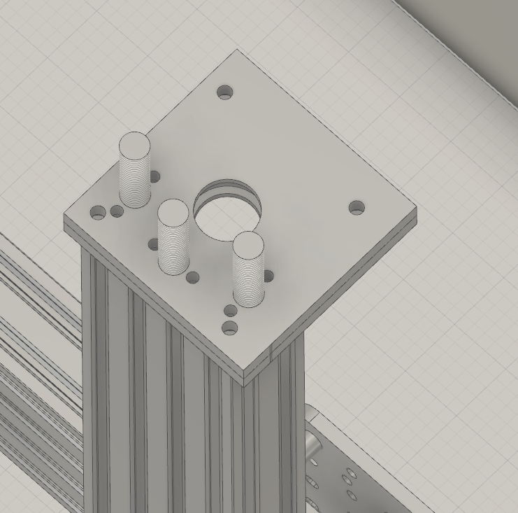
Figure 16: The z-axis equipped with M12 threaded rods
In this new design, three of the bigger holes in the C-beam are fitted with M12 threaded rods. On both sides spacers will be added and we will carefully tighten up the nuts. The induced tension in the rods should then take sideloads better than the unreinforced C-beam. We hope that this method of inducing pretension in the beam, gives similar results the use of pretension steel in prestressed concrete.[1]
[1]
[1]
[2] igus®- Energieketten, Leitungen, Gleitlager, Gelenklager und Linearsysteme
Open source large format CNC-machine and 3D printer
Build in 'Cartesian Style CNC' published by Sebastian-Schuetz, May 15, 2019.
For a schoolproject we decided to build this large format CNC-machine. The greatest part of the mechanics were sourced from OpenBuilds.
-
-
Build Author Sebastian-Schuetz, Find all builds by Sebastian-Schuetz
-
- Loading...
-
Build Details
- Build License:
-
- CC - Attribution - CC BY
Reason for this Build
We are huge fans of Frank Howarths work over at Youtube.com and watching him using the possibilities of his CNC-machine, made us want a big CNC too -
Attached Files:
-
Attached Files: