Let me begin by saying i am no expert! this project took 2 years to build learning everything from scratch.(could have been months if I had the time as this is only a hobby) ALOT of research on the internet an electrical background and about 2 thousand dollars not including the lead 1010 so a little bit on the pricy side. I'm posting this build a little late as I've already built the project but wanted to get some peoples opinion I have some of the build pictures i will share thru out.
My first journey was learning what I needed and wanted to continue my hobby witch includes building drones leds signs 3d printers and a whole bunch of other things, i needed a way to make my own frames for drones. i needed ways to make my own mounting plates for 3d printers. you can see where I'm going with this. So I went out and purchased a lead 1010 with the blackbox controller! waved my magic wand and poof half built!!
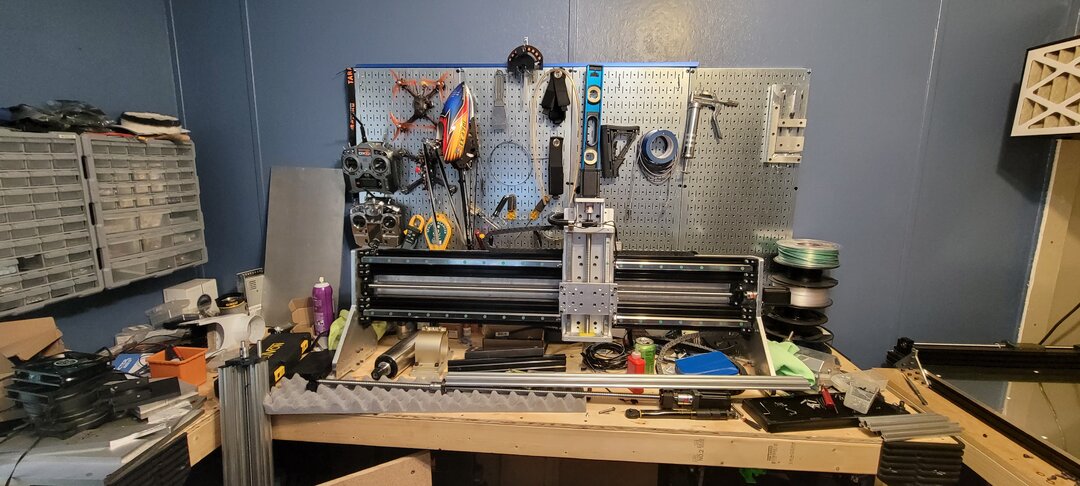
and just like that yay I had a machine that I've never used before. now I knew i wasn't getting something where you just pop in a part and waalaa! i love putting together really cool machines so this fed my appetite! this can be compared to a thanksgiving dinner or that BB gun that kid got on Christmas day. I live in Florida so I need a cool place to work and I happen to have a spare bedroom! waved my magic wand again
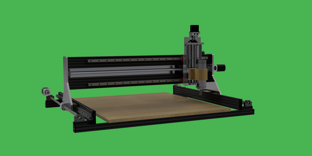
I had to make room by ripping out a closet door as this is my shop\office where I spend most of my time when I'm not at work. my first facing operation. this is where i noticed there was more to this than just the machine. and thus started the real journey of learning the software that controls the CNC, after months of learning how to draw in cad software i quickly realized that this was only half of the software and that i needed to learn cam software. another few weeks and i was on my way. now begins my journey of building the machine i needed. now no bad intentions to the people at Openbuilds they have awesome products and i purchased this machines knowing this wasn't really what i wanted. but was a really good starting point, to learn. so props to them!. i need something a little bit stronger and rigid so i can take on bigger projects using a lot of different materials as I plan on adding custom computer cases to my list of hobbies.. i liked the aluminum extrusion used even though i know it has its structural weaknesses . and thus started my design work inside the cad software i use. thanks to openbuilds extensive cad catalog i was able to insert most of the parts i used into my cad software design of the cnc machine mind you im not the best at drawling in cad. this design took weeks to make..
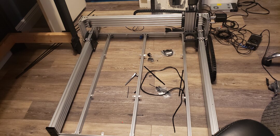
so now i had my design and began buying parts. I sourced some aluminum from online and used the lead 1010 to do its one out of only a few jobs and cut the arms which was really the only parts i needed to be as close to perfect as I could get them. now the lead 1010 can cut aluminum but it is more suited to wood this is my opinion. and the routers are really loud and being an electrician I've wired many many vfd and 3 phase motors so I chose to go with a spindle instead. I reused as much of the lead 1010 frame as I could but was only able to salvage a few things. always go bigger and better is my motto and if i were married id probably be hated by now.
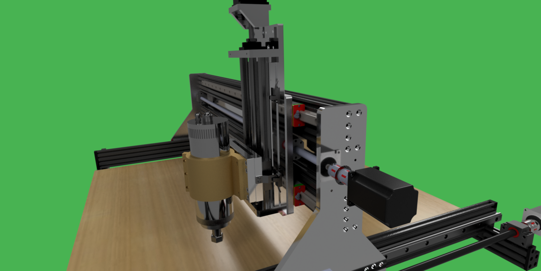
I used the outer frame as inner bracing for the new outer frame. i will try to include a list of everything used and bought and add it in at a later date. there were some parts i chose buy instead of making.. the z axis being one of them and for 250 dollars i bought a decent one on amazon. i messaged the seller and asked for a cnc design and they gladly sent me one. which is the one you can see in my cad drawing. waiting for parts i started building with what i had i cut the Z axis mount with the lead 1010 and the arms and you see i kinda followed what openbuilds did with their high z mod the extrusion has alot of ways to mount stuff which is what i wanted and why i chose to use it to mount the rails to. I also mounted a 1/4" plate of t6 aluminum to the back of the extrusion for added rigidity. i used t nuts to mount the rail to the extrusion we will see how these hold up as i plan to use the bigger better cnc to build an even better X axis.
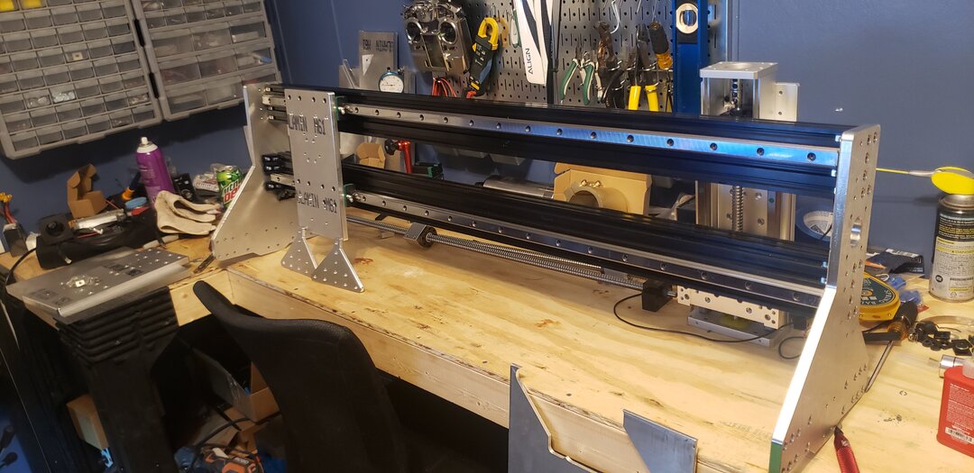
my next design will have more machined parts as ive become pretty decent as milling and cad design. the extrusion came in for the otter frame and right away i went into building it and checking to see if everything fit so far so good.
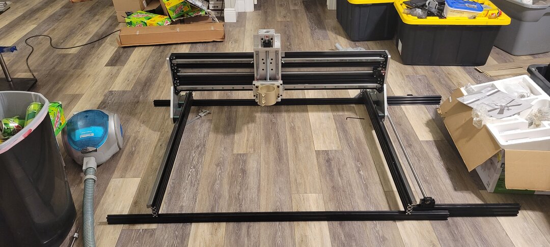
i had just replaced the floor in my home and you can see all the containers i put stuff into new ceiling fan too. but enough about the little stuff rough mounted the frame and X axis together to see how much bed i would need now came a big design question. i want to be able to mill acrylic and aluminum and wanted a coolant system. wood mdf bed or aluminum. 400 dollars later and an angry girl friend
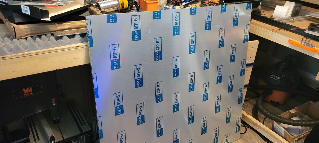
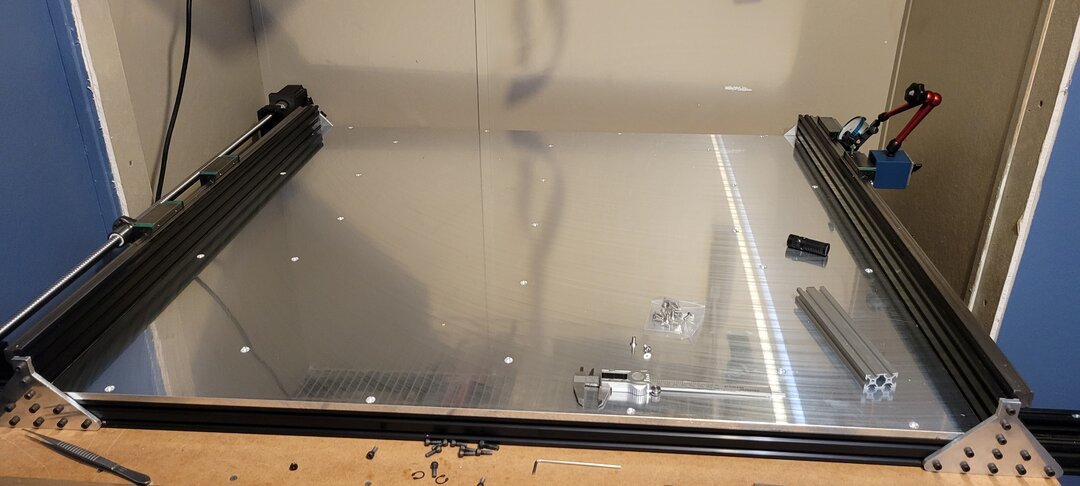
aluminum sheet grinded to ..015" over 12" i believe. was to heavy and big to slide in so i had to remove the x gantry.
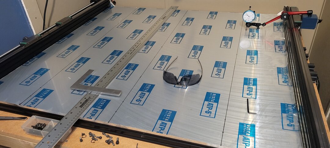
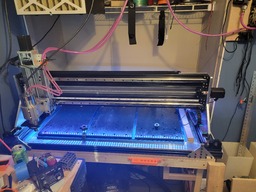
nothing is bolted down yet just playing with one of the many tools i had to have a dial indicator... bed was to spec and was exactly what i was looking for wish i went thicker though. i dont have a pic of the framing all put together but you can see the silver parts from the lead 101 in this next pic
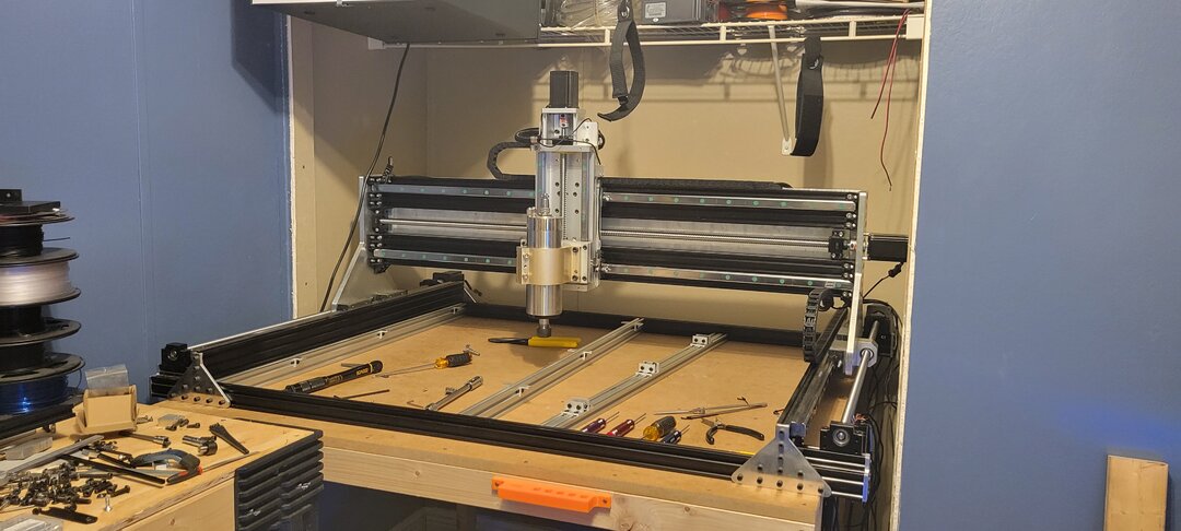
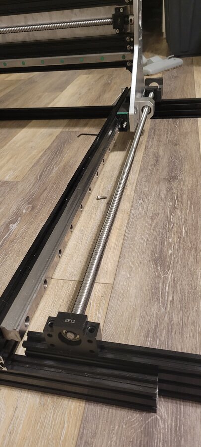
things are starting to look like a machine i reused the nema 23 high torque motors but plan on getting some servo motors when i make the bigger and better X axis you can see im going to use balls screws and linear rails if you haven't noticed already..
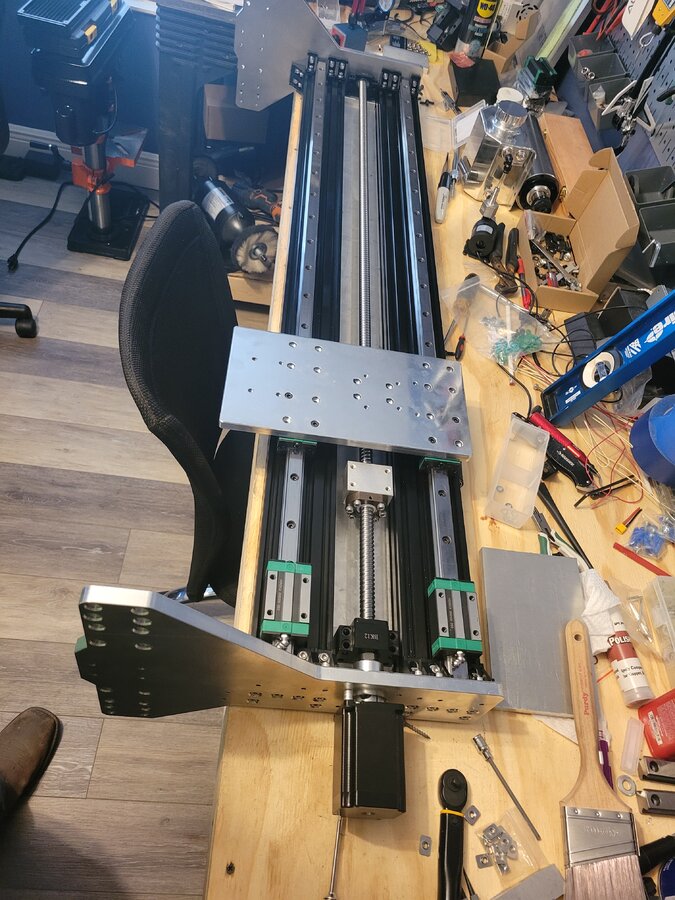
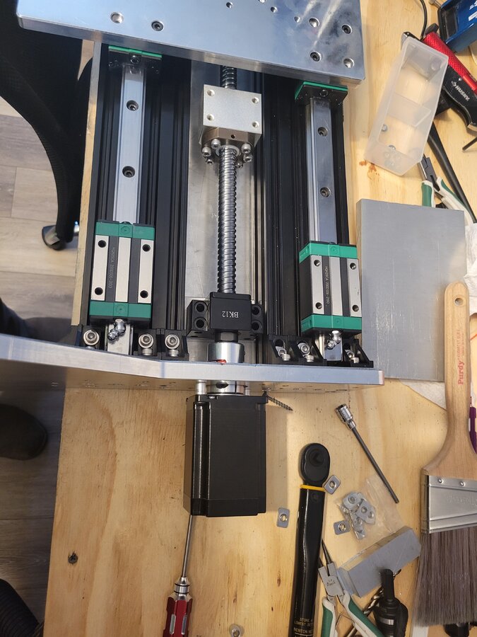
while i had the X gantry off i started to button some thing together on it. tried to mount the rails close to parallel as i could get them this was done many times through out the project this was to relief any binding issues i might get.. you can also see the 1/4" aluminum plate under the extrusion.
i had to mill another mounting plate for the x axis ball screw nut so i could mount the nut to the z axis mounting plate this was the real test for the lead 1010 as ive noticed from milling aluminum some things were getting out of wack. i started to get a lot of movement in the x gantry and z axis of the lead 1010 and i needed this plate to mill flat. and to be the right thickness which was off by .1" in my cad design. i ended up milling three of these before i got it right. if it wasn't at the right thickness it will bend the ball screw and introduce binding of the ball screw nut and bearings and increases ware we cant have that.
you can see my work bench is getting pretty messing need to get this out of the way.
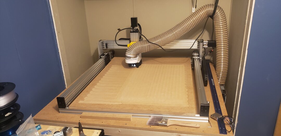
drilled and mounted the bed to the framing this was difficult doing by hand but i managed. getting it on the extrusion using tee nuts was the pain had to get help and slide it on. i mouted the x gantry back on and then mounted the z axis onto the x gantry i dont have pictures of this but here ive started to try and line things up better and check the bed to see how flat it was.
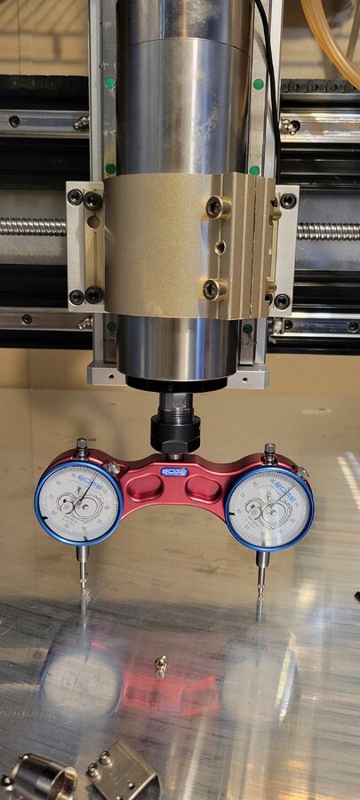
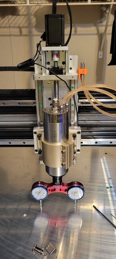
i trammed the z axis as best i could and started checking other parts of the bed its not perfect but we are talking hundredths of an inch so it will works for what i need this spindle is water cooled so i started running the hoses and designing the cnc pump. i didnt want a bucket of water to refill every time i used it so i went with an external pump and nylon tubing with silicon tubing attaching to spindle. now i don't know a lot about sizing pumps but this proved to be more difficult than i thought. i used a small 24 volt aquarium pump which i feel doesn't move enough water so i got a bigger one and now the tubing is to small for the pump.. ok got two pumps to use for various projects another day.. i would love to hear some of the more experienced cnc'ers comments on what they use. i ended ditching the brushless dc inline pump and went with a micro diaphragm pump. i haven't installed this yet and am still using the dc brushless 60 watt pump it works but the flow is slow because i cant turn the motor up higher with the size tubing i have on the input of the pump.
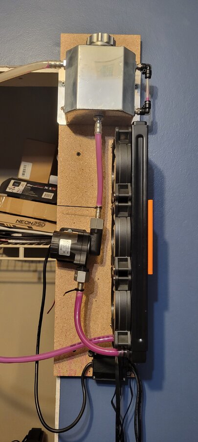
im open to any suggestions as i don't think this is as good as it could be and i just don't have the
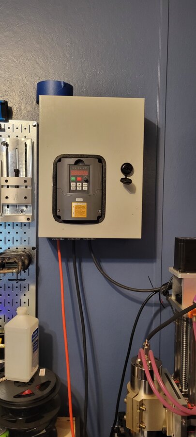
experience about designing water flow. now for something i have a little more experience in. VFD enclosure and a single 220 volt to 2.2kw. i didnt want to go into the hot Florida attic and run new wire and i dont use it everday all day i chose to run an 220 volt extension cord to the interior panel of my home. i then installed a 220 volt plug next to panel and roll the cord up when im not using this.. when i retire and have more time to do projects i may go a different route but for now this will do.. i know that having a grounded metal enclosure will help with EMI interference.
no cnc is complete without a 3Dprinted dust boot holder. this design hasn't faired me well and i will be making an acrylic dust boot with magnets.. i really need a boot that is easy to remove and get to the er20 collet. and one that is attached to the spindle so the distance from the project and the boot remain the same see some pretty cool designs of one and plan to make my own.
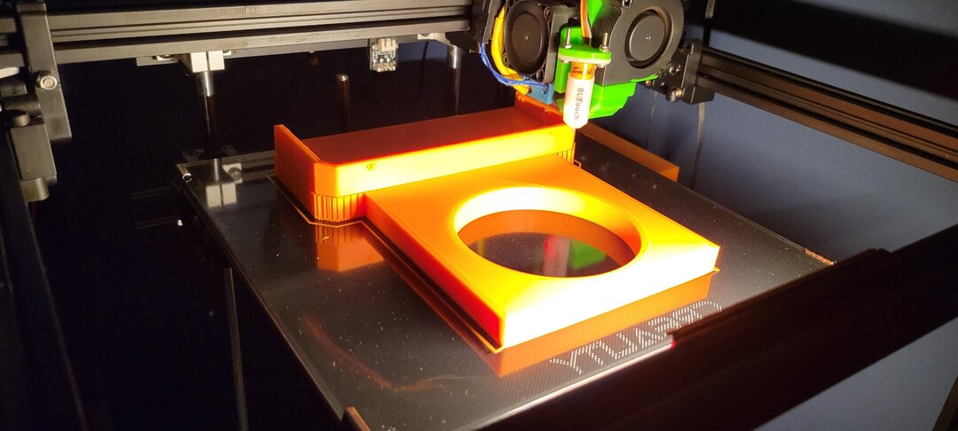
this one is orange and the one i kept is black needed to make another one to better the hole spacing.
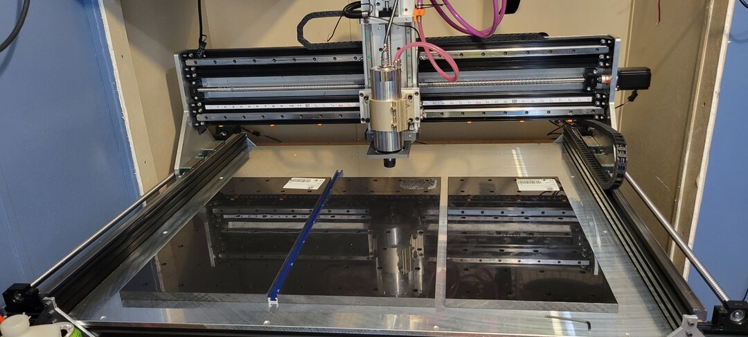
you can also see i mounted the waist board to the bed. i used derlin plastic or pom or acetyl there are so many names for this stuff. and was supper expensive 3 12x24x3/4" was 250 dollars.
in all i still have a few other things i need to complete but it works!!!!! and it works pretty good, the 2.2 kw spindle is wayyyyyyy quieter than the DeWalt router. i haven't had many issues with EMI yet. but i have had some issues with grounding. i have the x y z finder from openbuilds. its a great product but my frame is no longer isolated from the ground of the controller with the rubber rollers the lead 1010 has. i have a ground strap attached to the frame but my spindle is also ground to my vfd. which is then grounded to earth. if i unplug the vfd from the wall i can use the xyz finder but if my vfd is plugged in as soon as i touch the magnet from the xyz finder to the spindle i creates a path to ground and lights up. i dont want to disconnect the ground on the spindle as a fault there could energize the entire frame. i used shielded wire and have no EMI problems. if anyone has had this issue please let me know what you did.
MY first CNC build
Build in 'X/Y Table Style CNC Mill' published by Jasont, Sep 12, 2022.
my first cnc build using the lead 1010 to build bigger and better!!
-
-
Build Author Jasont, Find all builds by Jasont
-
- Loading...
-
Build Details
- Build License:
-
- GNU (GPL3+) General Public Licence
