
A while back @Mark Carew sent me some Makerlink connectors and some 20x20x500mm extrusions to see what I could come up with. Adding a few slightly modified Nema 17 Stepper Motor Mount Plates and some mini-V wheel assemblies lead to an extremely minimalist laser platform design. It should also be noted this design draws some inspiration from Skarab's Much4 - LaserV printed version but requires no printed plates.
Usable area on this design turned out to be 410mm x 410mm (16" x 16").
The original design was a simple rectangle with the front and rear framing members cut to 460mm to allow the 500mm gantry beam to reach both sides. After completing that version it became clear that support for the electronics would greatly simplify handling of the system so 3 Way Tee Nut Makerlinks were added to extend the design. 90 degree Hidden Tee Nuts were also added to support the minor framing members.


The Nema 17 Stepper Motor Mount Plates were modified by adding 2 additional 5mm holes 12mm above the existing upper row of holes to be used as wheel mounts. The bottom center hole was also enlarged to accommodate an eccentric spacer. The hole above the bottom center hole in the Y-axis plates was also enlarged to accommodate an offset mounting screw. The offset mounting screw was necessary due to the axle screw in the eccentric spacer also being used as a gantry mount screw and the two had to be in alignment for the gantry to be in alignment.


It should be noted that 1/4" spacers and eccentric spacers were used to help keep the 25mm axle screws from dragging the work surface. The framework was designed with no legs to sit flat on whatever was being engraved/cut and the 25mm screws would extend beneath bottom of the framework. Technically they are still 0.15mm too long but as they generally run a bit short it works out. (I did however have to grind down one screw.) You'll also note in the photo below the 2mm spacers used between the stepper motors and the plate. These were used to clear the axle screw heads. Three total were used with each stepper, one at each of the outboard screws and one trapped between the axle screw heads as there is insufficient space between the stepper screw and the adjacent axle screw to put the spacer on the stepper screw.

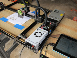
System layout is fairly simple. The electronics were all located along the right side. This allowed for switches and cords to be easily accessible from the front right corner. The board between the BlackBox and the power supply is a 12V buck converter for the laser. The buck converter should have been mounted farther to the left to avoid conflict with the power cord.


Wiring and limit switches were kept as simple and as tucked away as possible. They were still a bit of a challenge though. The two hop system of the flex tubing required that nearly all of the wiring had to go through the second length of tubing which was a bit of a tight fit. I also used some steppers I had lying around (non-Openbuilds) and they only had a 1m wire length which was a bit tight. Even keeping the flex tubing spans as tight as possible the X-axis motor wires reached the BlackBox with only 5mm to spare. (The moral here is stick with OpenBuilds steppers and their 7' cables and you don't have to stress over whether the wires will reach.) With a bit of creative mounting on the flex tubing I was able to get them to nest when the gantry carriage is all the way to the right. This allowed me to get a full 16" (410mm) of usable axis travel.


The adjustable laser mount while good in theory turned out a disappointment. This was largely due however to machining difficulties and the roughness of the surface of the standoffs. Will probably rebuild it when I get a mini-mill up and running.


The last few photos show the bottom of the system and the belts looping the pulleys. For the time being I have left the extra wire from the Y2 stepper but I may eventually cut it off. I placed some additional tee-nuts in the bottom slots in case I ever need anchor points for clamps to hold the frame to a surface.


Overall I was extremely impressed with the rigidity the Makerlink connectors add to the system. I can easily handle the system with no flex or skewing of the framework. One of the original goals was storing the system on wall hooks, hanging it by the left end (which is why I wanted the electronics mounted on the unit) and I see no real issue doing this. One suggestion I would make to anyone moving the system to storage is to unplug the steppers from the BlackBox as the gantries have a mind of their own when the system is tipped and you don't want the steppers zapping the controller.
The only thing I would probably change if I were to build another would be using 4 wheels on each of the Y-axis gantry plates. Trying to tighten and align the eccentric wheels while holding the gantry beam in alignment was extremely fiddly and I'm not sure it was worth the effort. I also noted a bit of flex (roll) in the beam when pressed although I don't believe any of that would be evident during use.
Sketchup files attached in the files tab. Both 3 and 4 wheel versions provided.
Minimalist Laser Platform
Build in 'Laser Cutter Builds' published by Rick 2.0, Aug 18, 2019.
Minimalist laser platform built with Makerlink connectors and modified Nema 17 stepper mounts used as gantry plates.
-
-
Build Author Rick 2.0, Find all builds by Rick 2.0
-
- Loading...
-
Build Details
- Build License:
-
- CC - Attribution Share Alike - CC BY SA
Inspired by
-
Attached Files:
-
