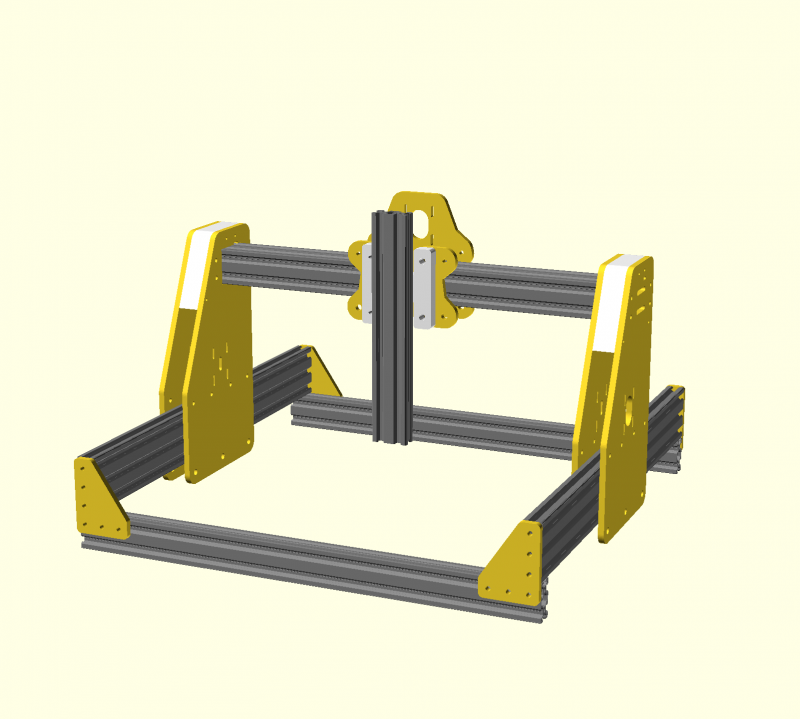
This is a mini desktop-router mostly for PCB milling that was originally inspired by the OX design. It uses 20x60 for the Y-rails, and 20x40 for the X and Z rails. All parts are designed in OpenSCAD, and is fully parametric. I mostly put this design together after I priced out a full OX system, and realized that it's somewhat overkill for light-duty PCB milling. It's heavily inspired by the OX design as well as the Shapeoko.

I'm a CNC mill novice; this will be my first machine. I was originally planning to buy a Shapeoko 2, but that was taken off the market very recently. Since I'm coming in from the world of 3D printing, I wanted to design a machine that I could build cheaply from old 3D printer parts, hence the Nema17 motors.
The gantry plates are laser cut from 1/4" acrylic, since I have access to a laser cutter. The acrylic was sourced from a local Tap Plastics, which had a bargin bin. I picked up 4 sheets of 11"x11"x1/4" acrylic for just $1.50 a lb, probably $8 worth total. I do not know how well this will work in terms of stiffness, but this apparently has been tried with other builds before. I will try to upgrade to aluminium gantry plates once the mill is ready to go.
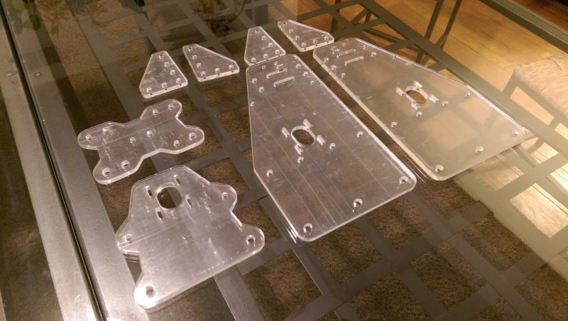
If the Y-gantry plates are too floppy, I have an alternate design with two additional plates and some printed spacers that should really shore up their strength:
I'm planning to build a spindle from a BLDC hobby motor. This little motor can push out 32k RPM @ 12V, as high as 600 watts! With the 2:1 pulley, this translates to a max spindle speed of 16k RPM. Since the motor is controlled via an ESC, this speed can be varied.

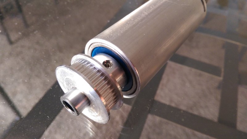
The spindle itself is built from an ER-11A collet from ebay with a 10mm shaft (http://www.ebay.com/itm/181644970648?_trksid=p2060353.m2749.l2649&ssPageName=STRK:MEBIDX:IT). I added a pair of 5200-2RS bearings (angular contact bearings, http://www.thebigbearingstore.com/5200-2rs-5200-zz-radial-ball-bearing-10x30x14-3/), which will be held in an aluminium tube. A spring washer applies a preload to the bearings, which is held by the top pulley.
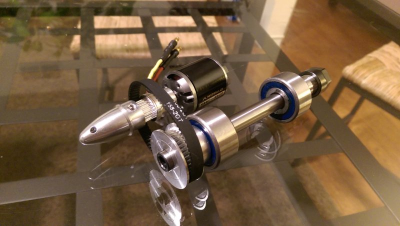
It was actually extremely difficult to find a motor that had the right combination of specs. I was hoping to find something that could put out 600W of power, around 20-30k RPM at 12V, with a 5mm shaft for the GT2 pulley. This is a 2700KV motor maxing out at 32k RPM@12V, about 600w, but it had a 4mm shaft. I used a collet-type propeller adapter to step it up to a 6mm shaft, which is much easier to find pulleys for. I figure that it could function as a slip clutch in case the bit gets jammed, but I have no idea how well it'll work. I found it on hobbyking, http://hobbyking.com/hobbyking/store/__21482__NTM_Prop_Drive_28_36_2700KV_595W.html.
The pulleys came prepackaged from ebay, http://www.ebay.com/itm/141546546702?_trksid=p2060778.m2749.l2649&var=440694851809&ssPageName=STRK:MEBIDX:IT. I have no idea what is the maximum RPM for the pulleys, so I'll be sure to start it slowly! The bearings will be held in place by a specially lathed aluminium tube (I have access to a lathe). If I can't get the tolerances good enough, I might just try 3D printing a case for it.
This is still a work in progress, and I'm waiting on my V-slot order to actually put the machine together. Since I'm mostly planning to use old 3D printer parts, the frame materials only cost me about $230 for a 500x500mm build. This should in theory cut in a 14" x 13" area.
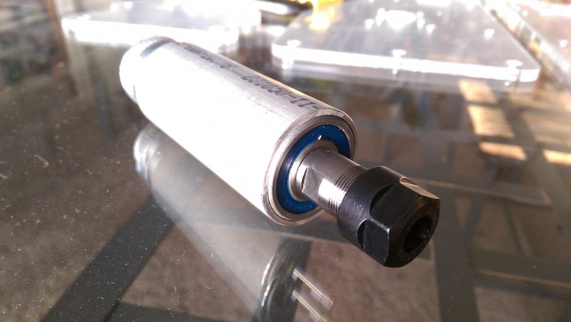
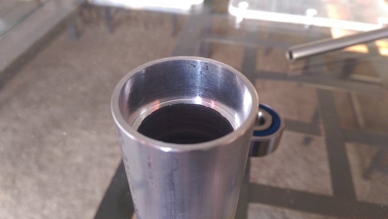
I visited my friend who's an experienced machinist today, and he helped me machine this schedule 40 1.32" aluminium pipe (https://www.amazon.com/gp/css/shipt...ringShipmentId=2123590660050&packageId=1&ref=) to a press fit with my bearings. It's absolutely beautiful! The spindle spins extremely smoothly, and is vastly stiffer than any dremel I've ever experienced.
I recently got my outrunner spindle running. Here's a video of it in operation:
These are the components I used to build it:
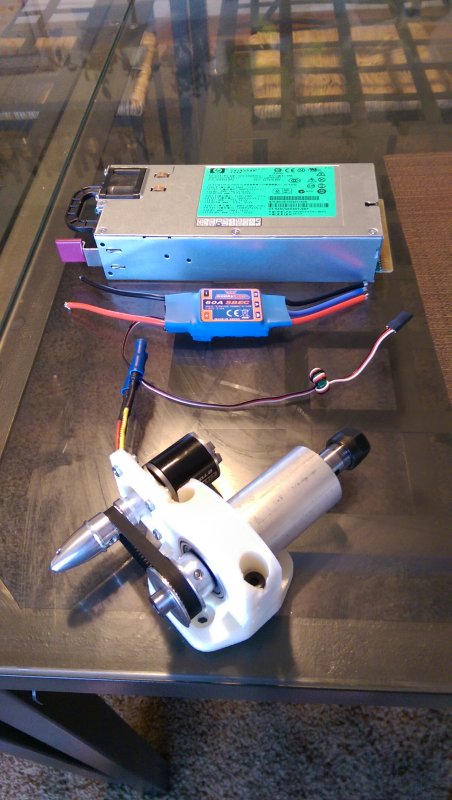
The power supply is an HP DPS-1200A server power supply, capable of 1200w on the 12V rails. The ESC is a hobbyking 60A ESC.
I can set the ESC to about 50% before the aluminum spindle tube starts heating uncomfortably. This translates to somewhere around 8000rpm on the spindle. It also seems like the rubber pulley tends to oscillate if I turn it up too much, making a louder buzzing noise. The pulleys have asymmetric set screws intended for steppers, which also induces some oscillation. I'm considering trying some 3D printed pulleys with symmetric set screws and round rubber belts. I might also drill out some vent holes in the aluminum tube and train a fan on it to keep it cooler.
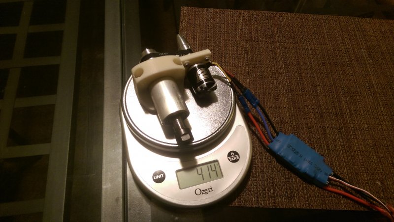
At 8000rpm, it seems like the noise is quite acceptable, far quieter than most dremels. The whole assembly is also pretty light, only 415 g.
My v-slot rail order is arriving on Tuesday --hopefully I can get the whole system built soon!
---- Update 2015-04-27 ----
Sorry for the lack of updates! I actually have the machine fully up and running now, and it's working great.
Here's some early progress pictures:
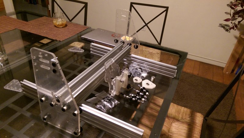
Here's the mockup assembly with all the wheels and rails. This was using the older version of the plates.
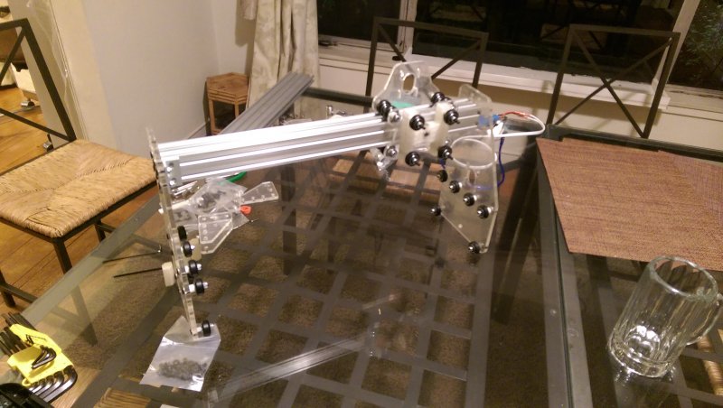
The assembled gantry...
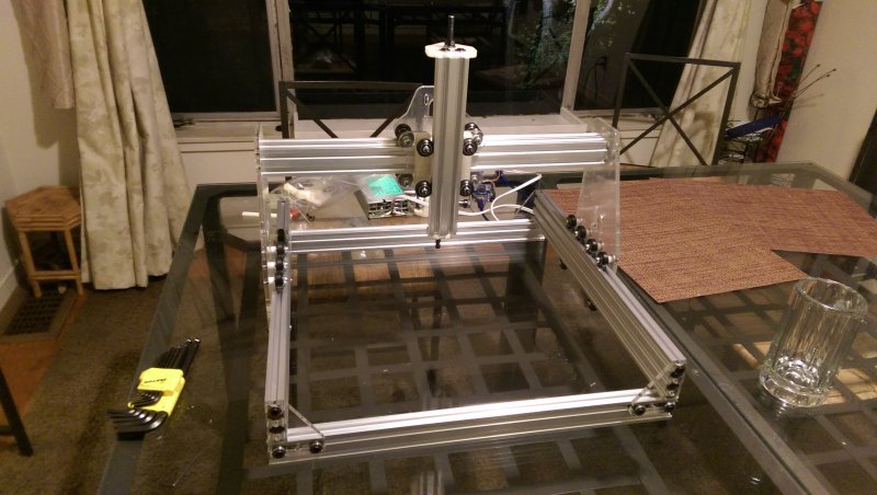
Fully assembled! Tapping the aluminum was by far the hardest part.
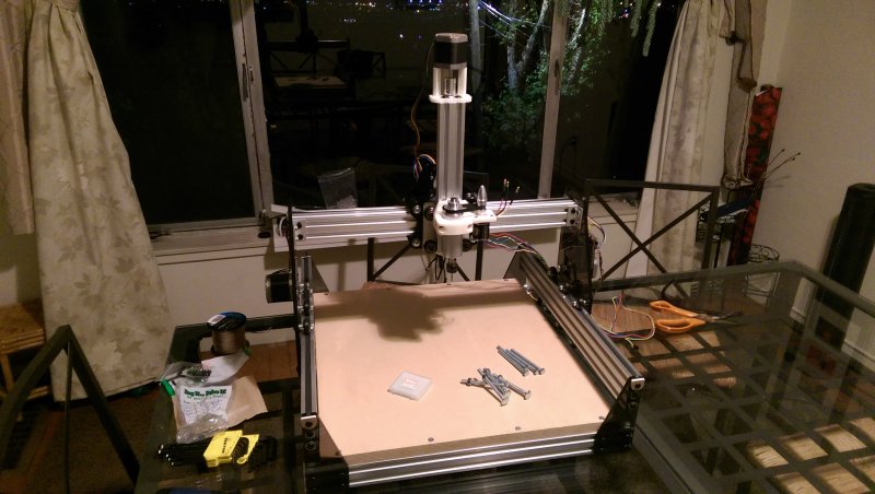
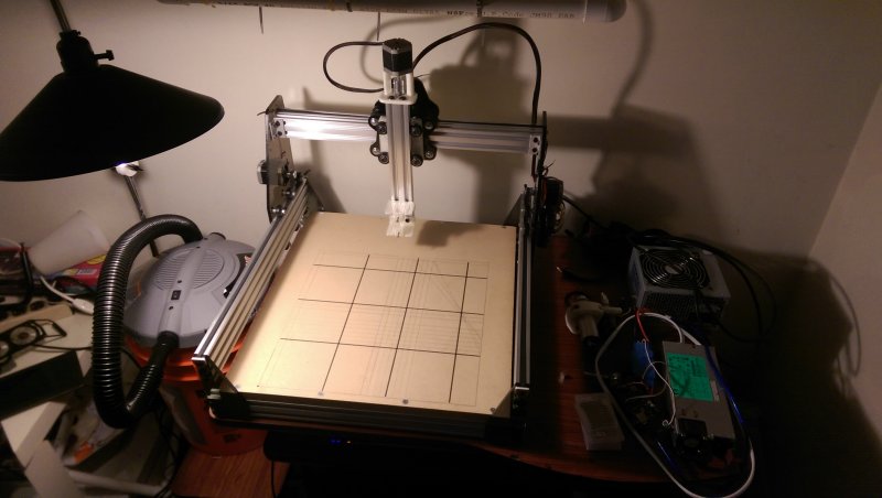
Here's the machine fully assembled the motors, a wasteboard, and the hobby spindle attached. This is using the new version of the side plates, with three wheels on top and three wheels on bottom. Also, the cast acrylic is marginally stiffer than extruded.
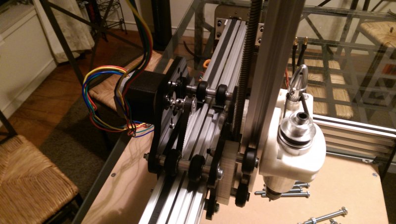
Detail of the X/Z carriage. The acme screw works a LOT better than the 8mm threaded rod I was trying to use.
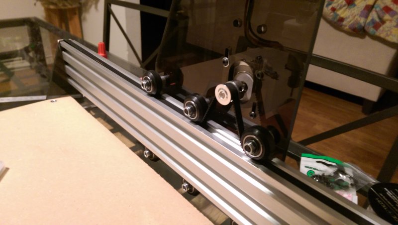
Detail of the new Y motor plates with the balanced wheels. This also lets me move the motor such that the belt engages more teeth.
Here it just drew its working area with a printed pen holder. At this point I was using an old RAMPS board with Marlin firmware to run the machine.
First milling job with the DIY spindle! 2mm step down, 200mm/min feedrate, 1/8" two-flute spiral upcut end mill. Probably somewhere around 12k RPM.
Sadly, the hobby spindle was somewhat of a failure. It successfully milled some acrylic, but the 3D printed brackets were not durable enough to hold the motor firmly. The motor bearings started getting creaky after just a few jobs, so I've retired the spindle. I purchased a Makita RT0701c hand router to go in the system, and it's a beast!
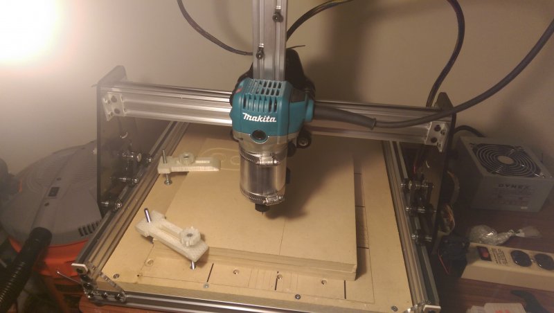
Here it is with the Makita router.
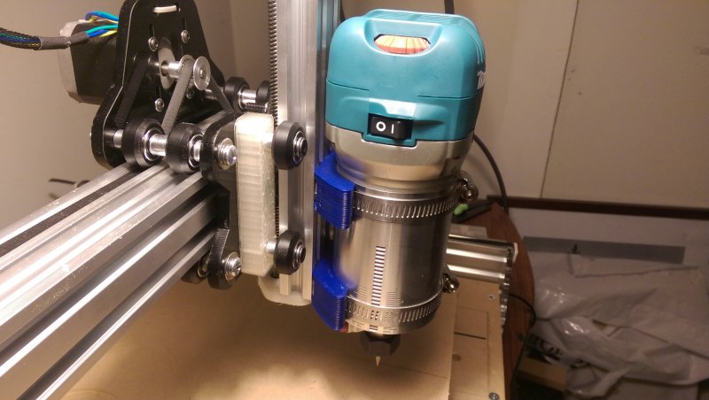
I 3D printed a pair of bracket that holds some pipe clamps -- it feels quite durable.
At this point since I was driving a much heavier weight around, I switched over to TinyG for the firmware. I modified my old RAMPS board by clipping all the 5V lines, and shorting the 5V rail to 3.3V. Then I just directly plugged the RAMPS board into an Arduino Due and updated the platform in TinyG2 with the correct pins. TinyG2 works great, and the RAMPS + Arduino Due setup is probably only about $40 on ebay!
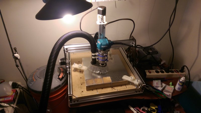
Here's the full setup with a dust shoe. This was shortly after my first attempt milling 6061 aluminum.
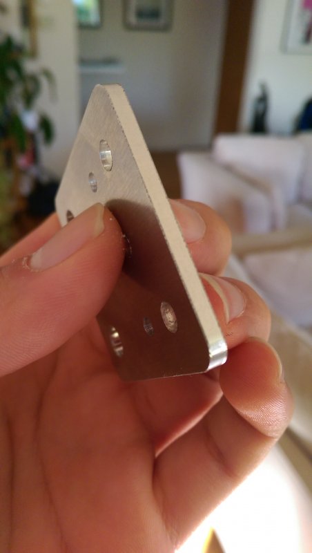
Finish quality isn't bad! 1/8" two-flute spiral upcut end mill, 400mm/min feedrate, 0.2mm step down, copious WD40, 1/8" 6061 aluminum sheet stock. One of those plates took 20 min to cut, but I suspect I could push the feedrate a bit -- the dust was very fine.
I'm planning to cut some new aluminum end plates for this mill, now that I've figured out aluminum. I've learned quite a lot while working with this mill, and I realized that 3D printers and CNC mills really should not be combined. Thus, my new design isn't nearly as tall.The new design features a much shorter Y motor plate, a separate spindle mount plate, and NEMA23 mounts. I'm toying with the idea putting the plates on the inside similar to the Shapeoko 3 -- this moves the pulley much closer to the motor body, allowing me to put more tension on the belts. However, this precludes the use of side shields, which I've realized can be pretty important. I decided to add a spindle mount plate because I noticed the majority of the flex I could observe was due to the Z rail acting as a long lever arm, pulling away from the wheels. A separate spindle plate means that any leverage on the z rail will be transferred to the carriage via screws, rather than the wheels.
To be continued...?
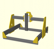
Mini-OX
Build in 'Cartesian Style CNC' published by James Gao, Apr 27, 2015.
An OX-inspired mini desktop mill. Designed in OpenSCAD, these parts are fully parametric and can be customized to your liking.
-
-
Build Author James Gao, Find all builds by James Gao
-
- Loading...
-
Build Details
- Build License:
-
- CC - Attribution - CC BY
Inspired by
OX, Shapeoko 2 -
Attached Files:
