
I started off with the Mini-Mill kit with the high-torque NEMA23 stepper motors and ordered a second spindle mount to help with the offset torque and an LED ring for illumination.
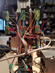
I then got an X-PRO CNC controller to run the steppers, only to discover that the high-torque steppers need a bigger driver, so I added the DQ542MA stepper drivers and added a 10-pin header to the X-PRO board so I could take the step/direction outputs to the drivers directly.
I also hauled out an old power supply capable of 48V/10A to power the steppers. I have to say that the combination of the stepper drivers with a big power supply turned out to be really really good. With some playing around with the serial monitor in the Arduino IDE I was able to get a pretty consistent nearly 1200steps/sec without skipping, so I backed off the max step rate to 1000/sec and I can haul a 1.5kw water-cooled spindle at speed with no steps lost.
I did also get the NEMA 23 mounting plate and the belt drive so I could flip the Z-axis motor over to the back side. I think it makes for a better mount and the possibility of swapping out a larger GT2 pulley on the threaded shaft for higher precision makes me happy.
I have a 500mm C-beam and threaded shaft that I plan to swap out for the existing 250mm X-axis. That provides for a larger X-axis workspace without going overboard, at least for me.
My next step is to add limit switches to the three axes and add some cable routing towline for the X-axis.
I also feel the need to make a work tray that rides above the surface of the XY plate to help keep all of the dust and chips from dropping right into the thread channel.
I'm considering a Raspberry Pi 3 running bCNC to act as the primary control interface and g-code sender. That will allow me to make this as a standalone "appliance".
It is still very much a work-in-progress as I am learning how all the pieces go together from the mechanical side to the software and control and even the modeling and CAM work.
----------
Feb14 update. Happy VD!
.
I downloaded GrblPanel and it was exactly the tool that I needed to exercise movements and get to understand g-code better. It's essentially a GUI for sending g-code commands to grbl and it's a very convenient tool for Windows users.
I've been wondering about cooling the steppers when they're idle. I do have the drivers set to reduce the current when they're idle and with the 48V supply, they're pleasantly warm to the touch. The hold is still stronger than I can wrestle away manually and that gives me some good confidence that this thing is not going to move once it's in place.
Oh, one other thing I'm working on. It's super-seekrit so don't tell anybody, okay?
----------
Feb18 update.
Recovering from the flu. I was able to find a set of six pretty decent microswitches that I think will work fine as limit switches. They have a definite switch action and seem pretty consistent.
Mounting them is another issue entirely. I have a good solution for the X and Y axes. The Z axis is a bit different and I don't have a mounting strategy figured out quite yet.
Something I'd like to stress: shielding of signal cables. When you can, use properly shielded cables. This is some signal wire that I had remaining from another project and it works very well.
----------
Feb19 update. Limit switches
I decided to temporarily mount limit switches with some heavy-duty double-stick tape. That way IU can experiment with some different locations.
I have some reasonably good places for the X and Y axes but the Z axis is problematic and I don't have a good solution yet.
Video link here:
----------
Feb. 23 update. Limit switches II
Taping the limit switches in place seems to have actually worked for the time being but I have another idea that I'm going to try. I picked up some small (6mm dia.) force-sensing resistors. I have some 1mm rubber sheet from which I'm going to punch small circles and glue to the surface with the back side having a circle of the double-stick tape on it to hold it in place. I should be able to mount those on the C-beam end plates right where the gantry plate meets just above the lead screw.
The resistors when untouched have a very high resistance in the several megohm category, but even a slight pressure drops them down into the 100k range with more pressure dropping it down to 10k. With a bit of simple added circuitry, this should make for a nice, durable low-profile limit switch.
----------
Feb. 25 update
Had the first fail of the tape-mounted switches. As expected the adhesive is not designed for shear force. On the good side, I made a set of the sensors to test and so far they look good.
Mini-Mill Enhanced
Build in 'X/Y Table Style CNC Mill' published by Rob Withoff, Feb 25, 2018.
Some enhancements of the basic mini-mill
-
-
Build Author Rob Withoff, Find all builds by Rob Withoff
-
- Loading...
-
Build Details
- Build License:
-
- CC - Attribution NonCommercial - Share Alike - CC BY NC SA
Reason for this Build
I wanted to make something that could help me make other things with higher precision and repeatability than I can currently manage by hand as well as learning how CNC works from beginning to end. -
Attached Files:
-


