
I've just started the design of this printer, I hope to finalize the hardware soon and order parts directly afterwards.
I plan to assemble all the hardware and then decide on electronics once it is complete.
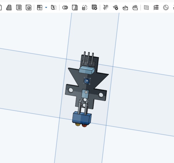
Here is a 3D DPF that will update automatically with each design change
Frame Assembly
Here are my current thoughts for the printer and electronic components:
E3D hotends
Belt Drive Bowden Extruder.
Edit: 3-8-2016
I have decided to go with the MKS V1.3 for this build. It's inexpensive, simple and I'm already familiar with editing Marlin Firmware.
LCD Smart Controller
BLtouch (auto leveling)

To be continued....
Update: 2-26-2016I have added the following to the CAD Model:

Z-Axis Drive System (NEMA 17 with M8 Lead Screw)
Y-Axis Drive System (NEMA 14 with GT2 belt drive)
Moved Corner Brackets to accommodate the Z-Axis Stepper mount
Added Side Braces to frame after moving corner brackets
I am adding a link below for a 3D PDF file. If Google Drive shows an open to open with Adobe Acrobat simply click it, if not you will most likely you will need to download the file to view it. It should then open with Acrobat Viewer, at that point you will be able to click on the image to activate the tilt, rotate and re-sizing functions...pretty cool stuff!!
Frame Assembly
Note: All parts in Blue will be either 3P Printed or Laser Cut
Update: 2-27-2016I got a lot of design (and redesign ;-) work done last night.
Finished locating all three axis motors, although I am still contemplating pulleys and attachment options for belts.
I changed the corner plates from flat plates to "L" brackets so I can use adjust feet on all four corners. I added the feet for extra space under the printer to hide the electronics.
I also added the the E3D V6 Hotend & Hotend Mount. I'll modified the mount (currently designed for a prox sensor) to add the BLtough Sensor.
After getting some feedback from the creator of the IndieLC I've decided to go with NEMA 14 all the way around. As I've mentioned the like the small form factory and they have been proven to be plenty strong enough in Indieflow's design.
Thanks for the input so far, I'm really excited about this build and look forward to put nuts to bolts
Until next time...
Been having fun printing parts as well

So it's been a busy weekend playing around with the design of this little printer, it has gone through many iterations in a very short time. I have come realize that no matter how hard we try sometimes it is simply not worth reinventing the wheel. With that said I've decided to take a more cues from the IndieLC...it is such a well designed printer there is really no room to improve on it. Although that was not intentions with this build nor the design concept, my hope is to end up with a very simple printer using as few parts as possible.
Update: 2-29-2016
For this version I have decided to make as many parts capable of being Laser Cut as possible. For testing purposes it is so much faster for me to Laser Cut a flat plate than it is to 3d print something, this will allow me to make quick changes if things don't quite work out. Of coarse having a Laser Cutter at home also helps
Please keep in mind that once this version of the design is complete you should be able to 3D Print all of the plates
The 3D PDF is up to date, and I also updated the main photos so they are a bit representative of the current design.
I have started populating the parts list.
Until next time...
Update: 3-1-2016I am very excited to say I just ordered all of the main frame and gantry hardware for all three axis. This will allow me to start the frame assembly, check fit of all the laser cut parts and check my overall travel distances. It will also bring to light any design flaws I may have over looked. With any luck I'll have the hardware by the weekend and I can get some time in on the project
Until next time...
Just finished laser cutting a bunch of plates...

Update: 3-2-2016I have decided to through yet another controller candidate into the mix...The ZeroPi I found that post from future_cncist (thanks). Since I use a Pi2-B and Octoprint to run my current printer it only make since to give it a try...to be honest it has quickly moved to the top of my list
Well kids, it looks like the ZeroPi is out. After chatting with the creator over on Kickstarter he has informed me that the first run of ZeroPi's will be the only run. They are now developing the "MegaPi" He expects to release info sometime in April, I'll keep an eye on their website for the post.
www.makeblock.cc
While waiting for the frame hardware from OB I have started another build...SL DLP 3D Printer...it should be another fun project
Until next time...
Update: 3-7-2016Since I'm waiting for the my frame hardware to arrive from OB (due in today) I decided to order some of the drive components. I ordered QTY (5) Nema 14 steppers motors and decided to give the MKS V1.3 control board a try. It was not at the top of my list, but it runs Marlin Firmware (my preference), it should do the job at a decent price and I simply wanted to see what it was all about.
With the hardware coming in today and the motors and controller averring tomorrow I should have a lot to do over the weekend
Until next time...
Update: 3-8-2016
I got most of my hardware last night...yeah I missed a few things and yes, a few things are changing. It seems no matter how well you plan things out on paper (or in this case CAD) you never seem to get it right the first time
I wasn't even through my hardware inventory when I realized I missed a piece of rail, ordered the wrong length screws and didn't have a single eccentric spacer. I order the "missed" hardware this AM and added a bunch of various length screws and a lot of spareshas taken care of that, so hopefully the project will be rolling again over the weekend.
I took a few photos of the hardware and had planned to snap more as I went along, but I quickly realized the effort was futile...I didn't have more the three components together before I have to drop back and punt. Oh well, that's what building is all about...you learn the best method of building as you go along, and lessons are learned when you have to pull something apart to install something you forgot.
With that said I've decided to take a different approach, at least different than I had planned...
I will fully assemble the printer, test it, and make any changes I feel are necessary to get it to it's completed state. At that point I will fully dissemble it and do a proper build manual.
In the meantime I will post photos as I go along with brief description of the build, what's going right, and what's going wrong.
Here are a few photos...I will add my comments later today or this evening.


Until next time...
Update: 3-9-2016Here are my thoughts on the build so far:
Almost everything went together as planned; the overall design is solid only needing minor changes.
The lower 20x40 rail is now a 20x20 rail (I’ll update the model soon). It was changed out of necessity (forgetfulness)…I needed (2) 20x40 rails and only ordered one. I didn’t want to wait for another rail to ship so I made a compromise. I added the (2) vertical tie plates to the vertical rail for the additional support needed due to missing two corner brackets...they made it plenty stiff enough. I actually like this a bit better as the lower frame is now symmetrical.
I did however model a few things incorrectly which required me to revise them and I’ll need to re-cut them as well. One was the X-Z Gantry plate. I modeled the wheels holes at 57.7 in-lieu-of 59.7. Needless to say the wheels were a bit too close to work, not a big deal and Solidworks is parametric so the change was pretty quick.
Another small issue was the corner mounts. With 10mm long screws they would not tighten up against the frame without a washer (in my case the 10x5x1 spacers). This is not a problem and I believe is part of the design of the bracket. However, the spacer at $.25 each and can get expensive when you need so many. I was able to find SS 10mm OD spacers at McMaster-Carr at $2.57 per hundred…a much pretty price if they are being used as actual washers. When you need the precision spacers they are well worth the cost, but they are over kill in this case.
I also needed to add washer to all the 3mm acrylic plates as again the 10mm long screws were a bit too long without them. I have since re-cut most of those plates from 5mm stock. Not having those washers makes the printer look so much cleaner!!
Well, I think that’s about it for actual build, at least as much as I can remember right now.
Additional work:
I have completed the final design of the Bed Gantry Plate and the Bed Plate itself. Both of which I plan to cut tonight. I ordered (3) 4.5 x 4.5 Buildtak Print Surfaces...I've never used these before but I hear good things about them, and since this printer is designed for low temp filaments (PLA) I thought it would be a good time to check them out.
I'm now waiting on hardware, parts, etc to continue the build...I'm not a fan of waiting
Until next time…
Update: 3-9-2016
It's been a banner day...got lots of cool stuff in the mail
MKS V1.4 Control Board
5 Nema 17 Stepper Motors
GT2 Belt (4 meters)
Unfortunately FT sent me (4) 5mm flex couples instead of the (4) 20 tooth pulleys I ordered...and they're nto answering my email
"Not sure why the photos are flipping over...weird!?!?"

Also printed all the bed parts...

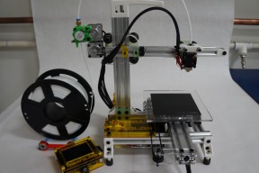
Here's an updated photos with some of the parts attached...I'm still waiting on OB hardware to finish the Y Rail and Gantry Setup...
Some of the best things are born out of necessity...I made this little beauty to tap the holes on the acrylic...
Until next time…
Update: 3-11-2016
I got a chance last night to add a bit more hardware to the build....
Installed the three drive steppers
Completed the belt drive system for the Y-Axis along with the print bed...my Buildtak sheets are due in today
Test fit the Z Gantry, as I mentioned I got the spacer wrong for wheels on attempt one. I'm still waiting for eccentric spacer and screws so it will come apart again, but the fit looks good so far.
Machined one end (opened to 8mm) of the 5mm flex couplings that FT sent me by mistake...they don't want me to send them back, so I guess that turned out in my favor
I should be getting the rest of the hardware from OB Saturday so I hope I'll able to finish most of the assembly then. In the meantime I will design a mount for the Control Board, and look at Extruder design and location. The Control Board has turned out to be a bit more of an issue as I had the size wrong originally. I think I can make it fit and keep it neat...it just might take some trial and error to get it there...
FYI: The X Rail is a short piece of scrap rail I had laying around, I used it to get a feel for what that Axis would look like, it will actually be a bit longer than that
Until next time…

Update: 3-12-2016I wanted to do a quick update so this is going to be short and sweet...I think
I got a bunch of hardware from OB today...YAY!!! I got stuff for both this build and my DLP 3D Printer Build.

So I was able to complete all of the drive system as well install the control board and some cable management. I had a lot of wins, and a couple of loses. I go into those as well as the assembly in the next day or two. I really just wanted to post a few photos for now to show the progress.
Even with some setback and some changes that will go into Rev-A I am very, very pleased with this build...I think in the end it will be exactly what I wanted and expected


Until next time...
Update: 3-16-2016Well, I must admit, things have been a little slow moving the last few days. Other than adding a power panel (still waiting on the main switch) and an electronics cover I really haven't gotten much done. However, all that's lacking now is the wiring, the hotend (due in Friday) and the final decision on an extruder. I think I'll be designing my own as I really can't find exactly what I want
It's not a big deal but I'll need to order a GT2 loop once i figure out the length, and that always takes a little time. Hopefully can I get the wiring done later this week and start playing with the firmware over the weekend
Here are a couple photos of the electronic cover...I had a lot if fun with this one. Not the best photos, but they'll get the point across
I can't believe it's been 5 days since my last update...sorry for the delay. Between work, not feeling well, and a little bit of laziness I've not gotten a lot done, but I do have a few updates I wanted to share.

Update: 3-21-2016
As far as the mechanical aspect of the build it's done for the most part. However it has not been without a lot of last minute changes (small changes, but changes none the less). Many of the laser cut parts are now 3D Printed, some were simply not stiff enough (Z Axis Motor Mount), others just didn't effort me the travel I wanted (X-Axis Idler Pulley Mount). I think I now have a nice mix of the two and as promised, even laser cut parts can be 3D Printed and I will provide STL's and DXF files to do either.
The wiring with the exception of the Extruder and Endstops is complete and looks rather nice if I say so myself. I went back and forth a lot on the LCD Graphics Controllers, RepRap Simple Graphics/Full Graphics or something a really nice like the Panucatt Viki 2. Although I wanted to keep this build inexpensive and the Panucatt does not quite fall into that category, this controller is not required to operate the printer, and you could run whatever one. With that said...I wanted to run this one
I got the Viki 2 in Saturday and whipped out a quick case with the help of my Laser Cutter...
I am also working on a Micro Extruder for this printer...I wanted to use a Nema 14 but needed a little more power so I'm going with a Belt Drive Extruder. Here's my design in the developmentally stages. I've printer several parts, over and over again ;-) and am getting closer with each one. Hope to have the design done and tested by the weekend...

Until next time...
p.s. sorry for not updating the CAD file, to be honest I lost a bunch of "mates" and now it's in shambles LOL I'll get it cleaned up as soon as I have time and will post when it's done.
Edit: 3-21-2016
Here are a couple pix of the extruder printed, it will require a few tweaks, but it's a solid design
The last photos shows my Nema 14 Micro Extruder next to The Itty Bitty Nema 14 Extruder...I think Micro is the correct term


Until next time...
Sorry for the really crappy video...but I wanted to show you guys that it was actually alive and kicking
I have an issue with the Z probe I need to work out, but once I get it sorted I'll post a better video of the entire homing, auto bed leveling process.
Until next time...
Update: 4-3-2016Well, yesterday was a big and exiting day for the MSL-5 Canti Printer...it made it's very first print!!! I finally got the Firmware sorted out and also decided (after some internal struggles) to ditch the Auto Bed Leveling. At first I thought I'd merely skip it for now, get the printer running and then add it later, but after taken more than a few factors into consideration I've decided to ditch it all together (at least for now).
The frame is all metal, super ridged and there should be no reason (other than loose hardware) for it to ever move and become "out of level". So once it's initial leveling is done it should be fine for the long haul. The only exception to this would be multiple beds (like my Prusa i3). I did make the bed attach magnetically for that very reason, along with being able to remove the bed for easier part removal, just give the bed a little twist and the part comes right off...it works great!!!
I do have a BLtough lying in wait for this project, with time I might still add it as an option!?!?
As far as I'm concerned, and with the exception of a few minor refinements I will be declaring this Build Complete as soon as the thread is updated and finalized.
Here's a hit list of the items that need to be completed (Updated) in the thread:
BOM
STL (printed) part uploads
DXF/PDF (Laser Cut) parts upload
Assembled/Setup Details (broken into sections)
Frame
Z Gantry
X Gantry
Y Gantry
Build Bed
Extruder
Electronics
Firmware
CAD Model
Haha, that list looks pretty daunting now that I've typed it, but it should come together quickly...
Here are a couple photos of the first print and a short video of it as well. I have a longer video I'll be editing and posting soon


Until next time...
WOW!!! It's hard to believe it's been over two months since my last update on this build (time really flies). Sorry for the long hiatus, but work got in my way LOL. I spent almost 5 weeks in sunny CA on a business trip. I spent most of my time doing tunnel support at the NASA Ames Research Center in Silicon Valley. We built a model that was flying in the NFAC Tunnel, the tunnel has two sections, a 40'x80' and a 80' x 120' section. Those are the sizes of the actual test sections, this is the largest wind tunnel in the world. We actually had models in both sections although I was only working the one that was to run in 80 by tunnel. I know this has nothing to do with OB or my build, but it does however lead to something that does - Maker Faire Bay Area. Yes, I was lucky enough to be in the area on the weekend of the fair, so I got to go an hang for an entire day. Stay tuned for a Blog Post by Mary for all the details and photos, and now that I'm back on the East Coast I hope to head up to DC tomorrow for the National Maker Faire
Update: 6-17-2016
Now onto the task at hand...while I was away a ordered a few little upgrades for the Canti. The first was the MKS TFT28 touch screen controller. What a great upgrade!!! The Canti is now running fully standalone. I can upload files from a SD Card or USB Drive. This was truly PnP, I literally plugged it in and turn on the printer, everything worked with no Marlin changes needed. The only slight glitch is the Chinese Text at the bottom of the Icons. It can be changed with firmware, I just need to figure out hoe to do that...if you can help, please let me know.
Here a short video of it running standalone printing spacer for the Acrylic Enclosure I designed this morning.
The other item I got as the PiBot IR Sensor that I will use for Auto Bed Leveling.
It should wire up and work the same as the Inductive sensors, but it is much more compact and will hopefully fit well on the smaller print head setup. I have not quite solidified the mount or location, but hope to do so in the week or so!?!?
I do however have it modeled in Onshape
My final note is that the printer is functioning perfectly, and I don't think the design will need changing anymore so I'll start compiling the necessary files and get them uploaded as soon as I can...
To be continued...
Update: 6-20-2016I just got the TFT Enclosure done and the ribbon cable sheathing installed. Here are a few photos of the completed assembly. I also updated the firmware so I now have English Text
To be continued...


Update: 6-23-2016Just thought I'd add a few photos of the completed printer.


MakerSL MSL-5 Cantilevered 3D Printer
Build in 'Cartesian Style Bots' published by Sonny Lowe, Jun 23, 2016.
This is a simple cantilevered 3D Printer. It is designed around the OB V-Slot linear rails. I am trying to simplify this as much as possible, all rails will be 250mm long and only one will require cutting (it will be cut in half). The printer will use all OB wheels and gantry plates where applicable, all other plates can be either Laser Cut or 3D Printed (files will be provided for both). I am not set on electronic as of yet, but plan to use a single control board...no Arduino/Ramps control.
-
-
Build Author Sonny Lowe, Find all builds by Sonny Lowe
-
- Loading...
-
Build Details
- Build License:
-
- CC - Attribution - CC BY
Reason for this Build
I wanted a small, simple, easily to built PLA printer. Something I could build myself with smooth and quiet linear movements made from quality components. The OB V-Slot system was the perfect match for all my requirements.Inspired by
The IndieLC -
Parts list

![[IMG]](proxy.php?image=http%3A%2F%2Fwww.pibot.com%2Fben%2Fauto-correct-building-platform%2Fdistance-from-sensor-probe-to-the-extruder-nozzle-is-near-10mm%2520.jpg&hash=909fe474806c56eedd842d5480d3d85b)


