
Since I've been working on and off on building a rolling push for the CNC machines I decided it was time to improve my dust shoe.
Just because I am the way that I am, I thought to myself "how can I make things shoe a little more me?" so I instantly thought of adding lights. That idea then sat in my head for a day or two and it started evolving a little. Ultimately I decided I wanted to add LED lights and see if I could add a camera inside the shoe so that I could do timelapse or just be able to see my work in progress.
I then started trying to design this thing in my head and the biggest obstacle I could see was how I was going to be able to wire this thing. The real issue is how do I remove the bottom half of the shoe, where I was planning on putting the lights and camera, without having to disconnect everything. Every time I use the probe on the CNC I remove the bottom half of the shoe, adding lights was going to make this process very tedious and I would ultimately hate doing it every time so I needed a better way.
So right now I'm working on making the magnets that hold both sides together be the 5v, G, and Signal cable needed for addressable LEDs. If I want to use a USB camera then I also need 2 more cables/magnets Data + and Data -. So I settled for a 5 magnet design. The LED light would use 5v, Ground, and Signal, and the USB camera would share the 5V, G, and use the Data + and Data -. The only way I could possibly make this work would be by making my own PCB and that's what I did.
I spent a few days watching videos on how to use KiCad to design your own boards, I drew up a concept, tried it, and to my amazement it worked! It looks crappy but for my first attempt, I was happy.

Now knowing that I have the ability to make my own simple one-sided PCBs, I did more thinking designing, and editing and made my first workable two-sided PCB. As of right now my jig with end up using two custom PCBs, the top one being one-sided with the magnets soldered on board, and the bottom one being two-sided, one side will have magnets and the other side of the board will have the LED lights.
I think my biggest challenge now will be making sure all the magnets make contact. They line up perfectly but if one magnet is slightly more raised than the others, then the other magnets might not make contact.
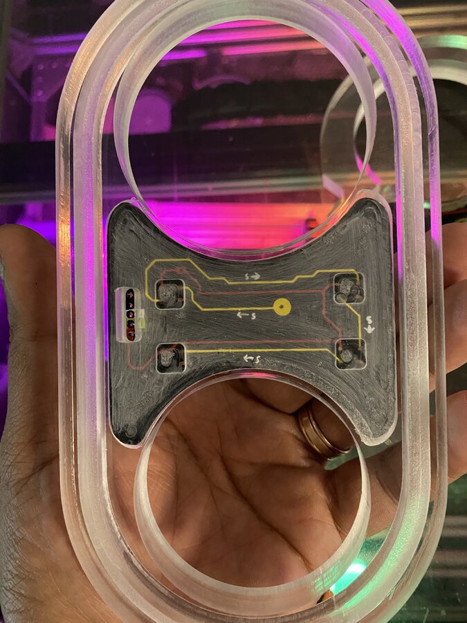
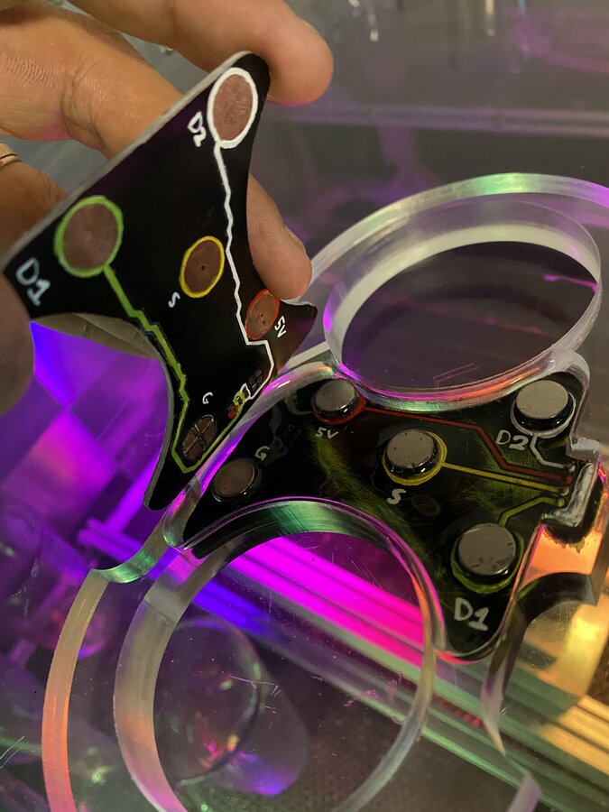
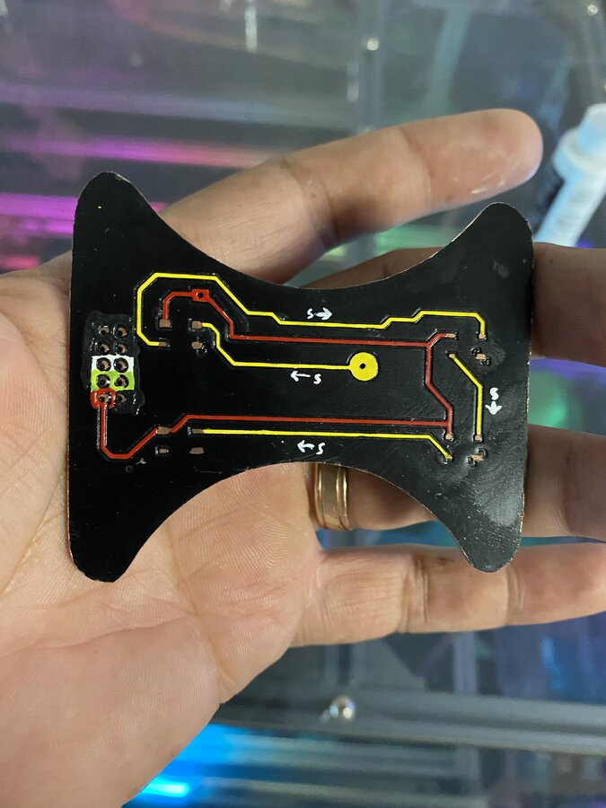
Since this is a prototype I painted and color coded the PCBs so that I can easily identify what’s what. I know it’s not the prettiest thing but it will do for this test.
So I went ahead and finished the bottom PCB and tested it.
I made a mistake and messed up the bottom half of the shoe itself so I'm waiting on more acrylic to get here so I can finish this properly, It should get here sometime tomorrow.
This is still a work in progress and I'll be uploading pictures and videos as I go along.
Magnetic CNC Dust Shoe with LED lights and Camera*
Build in 'Everything Else' published by CChico, May 21, 2021.
Making my own magnetic dust shoe with led lights and a camera. Showing my progress from beginning to now.
-
-
Build Author CChico, Find all builds by CChico
-
- Loading...
-
Build Details
- Build License:
-
- CC - Attribution NonCommercial - CC BY NC

