LDMS CNC Build
Lithgow District Men’s Shed is an AMSA (Australian Men’s Shed Association) affiliated Shed in the small coal-mining town of Lithgow in NSW, Australia. Late last year (2017), a couple of the members thought that a CNC router might be a nice acquisition that would complement all the other wood-working gear we have. So, two of us more technically-minded folks were given the task of finding out how much one would cost and putting up a proposal to the Committee.
We soon discovered that a completely built shop-bought CNC router was beyond our means. But I have a background in hobby electronics, and also professionally in computer controlled instruments, so we felt it would be worth a try to make our own based on the Large Ox kit from Makerstore Australia. The Committee gave us two Bobs the (more than) two bob needed to purchase the kit, and off we went. Heidi at the Makerstore was most helpful in arranging the purchase and delivery of our kit.
This is the story of our build. It is part cautionary tale, and part proof that if us bunch of old geezers can manage it, anyone can. We had quite a few problems on the way, all of them from way left of field, but all eventually overcome.
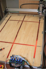
This is an overview picture of the machine, minus the router.
It is at its “machine zero” position. We have added a plywood base board with some 1200 mm long T-tracks which will be used to hold work-pieces in position. The electronics are at the near end, and it is equipped with an emergency stop “kill all power” button for safety.
The electronics are Arduino based with a CNC hat equipped with Polulu A4988 stepper drivers. In hindsight, maybe not the best choice, as the steppers are 2.5A rated, but the A4988 is 2A rated. So, if (when) we eventually burn them out we will look at higher rated drivers to get the most from the steppers.
Mechanical Build.
This is styled as a “kit”, but that is gilding the lily somewhat. It is more a box of little bags filled with miscellaneous bolts, nuts, aluminium extrusions, wheel, bearings, washers etc. Fortunately, the instructions were reasonably clear and all the bits were included. We encountered only a couple of issues that probably need some warning.
The first is, when you build each of the X, Y and Z gantries and assemblies, make sure you properly adjust and tighten all the wheels and have them running smoothly before you assemble the Z to the X and the X to the Y assemblies. You will not have access to the bolts once the thing is assembled!
The second is that you must make sure that use a new, sharp tap and keep it running true when you tap the holes in the ends of the extrusions. You will get no second chances if you strip the threads, or they go crooked. Fortunately, we have a couple of retired fitter / turners on hand to do such things for us.
It would be prudent to order a few extra t-nuts, screws and washers. You will need them for mounting all the other little bits and pieces, such as the electronics, the cable management, base board mountings, and so on. We ended up ordering extras once we started on the electronics.
Figure 3 Another view of completed machine
Electronics Build.
There are no instructions provided in the kit we got. You’re on your own, buddy. Fortunately, there is a whole heap of stuff out there on the internet. But if you don’t have some experience in building electronic gizmos from scratch, and you can’t do fine soldering, you should enlist the help of somebody who does.
The box containing the electronics was obtained from Jaycar, as was the fan and all the circuit board connectors. The blue and black plugs (2- and 4-pin) for the motors and limit switches came with the kit, as did the 2- and 4-core screened wire. The drilling templates for mounting everything in the box were done in LibreCAD.
A fan is recommended. The heatsinks on the A4988s will get very hot. But the power supply to drive the stepper motors is 24V. I discovered in initial testing that the Jaycar 12V fan will run (furiously) on 24V, but it smells a bit. My fault, I just wasn’t thinking too hard when I connected the fan to the main dc supply. Problem solved by stealing the 12V supply from an old internet modem.
Because the CNC shield (from Protoneer) was the version designed for GRBL 0.8c we decided to stay with it rather than go to GRBL 0.9 and re-arrange the wiring. This is purely for future maintenance purposes; better that you stick to the wiring as labelled on the board and not confuse things. The machine will be used in the Men’s Shed workshop by members, and future maintenance may be by somebody else who will be unfamiliar with the thinking that went into the build. We may revise this decision in the future, but at that stage we would get the newest possible revision of the CNC shield, run the version of GRBL it is designed for, and install higher rated drivers.
Figure 4 The box of electronics
Overall assembly
There are quite a few things to consider when doing the final assembly.
We built ours with future maintenance, modification and upgrades in mind, so all wiring is either pluggable (at the electronics end) or in “chocolate block” style connectors. This necessitated the addition of mounting brackets to hold all these bits and also as an anchor point for the cable drag chains.
To minimise the number of drag chains, you will need something bigger than the 20x10 mm chain supplied by default. If you want to get 4x 4-core cables for the steppers and 4x 2-core cables for the X- and Z- limit switches kept in one drag chain you will need a 30x15 mm drag chain to run from the electronics case to the end of the X-axis assembly. To get from there to the X- and Z-axis steppers the 20x10 is fine.
When doing the wiring, keep in mind how you want to ground the screens of the cables. The screens should (must, even) be grounded at one end only – the other end is left unconnected. Best is to connect the screen at the “source” end – in this case, at the electronics. Label everything, record everything and test for continuity on every core. NO exceptions!
For the drive belts, we opted for the “double belt” system to minimise stretch and backlash due to belt stretch. This means laying one belt teeth up in the track and the other teeth down and meshing with the bottom belt and running over the stepper pulleys.
Figure 5 Some construction details
Setup and Testing
This is where it really gets interesting! First you need to install all the software you need on the PC you will be using. OH, and make sure the PC is powerful enough! We found that our old AMD A10 powered PC could barely stagger along running windows, never mind do any actual work. That resulted in a big delay while we re-purposed the administration laptop, got it upgraded to Windows 10, and got the LAN working properly. Whole story all on its own!
We installed the Arduino development environment (that is optional), the Universal G-code sender (UGS), FreeCAD and Fusion 360. But FreeCAD in its current form (V0.17) doesn’t play nicely with Windows 10 (to do with Windows and Qt4 not playing well together), so don’t bother with it (yet). Learn how to figure out which USB port is assigned which COM port. [Hint – it’s under “Device Manager” from the Start menu]. Fusion 360 is really easy to learn, and will do tool paths and can create GRBL G-code. Also install a G-code simulator. We have installed CAMotics, but not tried it out. Universal G-code Sender also has a simulation mode.
When setting up UGS, you will need to set up some of the modal (ie remembered forever, or until changed) settings such as the number of steps per mm on each axis. This is where you find out that not all PCB jumpers are created equal. We started with our z-axis tracking fine at 100 steps per mm with the drivers set for quarter stepping. Then one day it suddenly changed to doing 40mm when asked to do a 10mm movement. That is why you MUST install limit switches. The jumper for micro-stepping selection had worked loose wasn’t making contact. Easy to figure out (lose ¼ stepping and go to full stepping, and you will go 4x further). But could have been messy.
As part of this you will have to calibrate the current limits on the stepper drivers. We have cheap Chinese copies of the genuine Polulu drivers, so the setting resistors are not the same value. So we had to work out the voltage setting for our required maximum current for ourselves. Again not hard, there is plenty stuff out there – Google is Great! If you don’t do this and they are set too low you will not have enough drive to go at any speed, and the motors will stall and make UGS very unhappy. If set too high, you will let the smoke out of something, and believe me when I say you won’t ever get the smoke to go back in.
Maximum feed rates are just a question of trying higher and higher numbers until the motors hit the current limits, then back off about 30-40% (less if you feel adventurous).
What’s Next?
We still have to fully commission the machine. We have it set up now so that it will go “Home” based on limit switch positions on command, and we have set up a “library” of work-piece home positions. The plan is to move this around to even out and distribute the wear on the drive belts.
A test piece (based on the circle, diamond, square) has been designed in Fusion 360. We are yet to decide on the tools we will be starting with, so any CAM modelling we do in F360 will be purely a learning exercise for now. We will use the “test” G-code file generated by F360 for the toolpaths and try it out in a simulator before trying it on the machine with no spindle attached as in “in air” test.
If that’s all OK, we are good to go and try it out for real!
For all modelling we will strictly enforce the sequence of digital model simulation (CAMotics or similar) then “in air” with no tool and then finally the live cutting.
If you want more details on setup and how we did things, just give a yell in the forum and I will be happy to help.
Lithgow Mens Shed CNC build
Build in 'Cartesian Style CNC' published by RobFromLDMS, Nov 21, 2018.
The tale of how we put together our CNC Router, and some of the difficulties encountered. It is now ready for final testing and commissioning.
-
-
Build Author RobFromLDMS, Find all builds by RobFromLDMS
-
- Loading...
-
Build Details
- Build License:
-
- CC - Attribution - CC BY
Reason for this Build
Built as an inexpensive way to try out CNC routing for woodwork projects at a Men's Shed. -
Parts list
Qty Part Name Part Link Comments 0 Link -
Attached Files:
![[IMG]](https://openbuilds.com/file:///C:/Users/robc1/AppData/Local/Temp/msohtmlclip1/01/clip_image003.png)
![[IMG]](https://openbuilds.com/file:///C:/Users/robc1/AppData/Local/Temp/msohtmlclip1/01/clip_image007.jpg)
![[IMG]](https://openbuilds.com/file:///C:/Users/robc1/AppData/Local/Temp/msohtmlclip1/01/clip_image009.jpg)
![[IMG]](https://openbuilds.com/file:///C:/Users/robc1/AppData/Local/Temp/msohtmlclip1/01/clip_image011.jpg)