
So long story short after some intense reading/web browsing I came across a bunch of freeware programs and got things working. I then built an x-y axis assembly
Some time passed and then I came across the awesome open rail and Delrin v groove wheels available in the open build store, my mind went into overdrive and decided it was time for an upgrade.
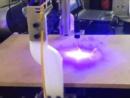
Here are the end results and I couldn't have been more happy.
Well enough talking and on with how you can build your own.
First thing is to get all the electronics out of the way, I ordered most of my items off eBay for cheep and didn't mind the wait from China as I needed time to plan.
Step 1
Assemble your Arduino Nano
Next would be to get the arduino up and running with the proper software, we can worry about the configuration later.
At some point in this post you will have access to all the software and my configuration files
Follow the link, download the required programs and follow the instructions
Link for flashing the arduino with mine or your own grbl hexFlashing Grbl to an Arduino · grbl/grbl Wiki · GitHub
If you followed the instructions correctly you now have a g-code interpreter that will control the driver boards and laser driver circuit.
Next we need to get the drivers ready. If yours came pre assembled then feel free to skip along and read on to where things pertain to you, if not this is what I had to do
Assemble the drivers
I then had to build heat sinks for them as they tend to get hot and I saved a bit of cash by ordering them without heat sinks.
Cut to size, sand, clean, paint and presto!
Arctic Silver Thermal Adhesive is what i use to attach the heat sinks to the stepsticks and arduino
So now instead of waiting around for paint to dry, let’s start on the laser driver.
It is a simple design using the great little LM317 in a voltage reg configuration then feeding another in constant current configuration. This will allow you to use a laser diode from .125 ma to 1 a.
In this build I am using a 445nm diode from a projector and it will be around 1w.
Before you go playing with any type of laser you should read up and learn about laser safety and take all precautions, you only have 1 set of eyes and faster than you can blink you will be blind.
For the $15 bucks or so it cost on eBay for safety glasses it’s not worth the risk.
First circuit Voltage Reg that feeds second circuit
The second circuit, this is for your standard laser diode from a DVD burner but still works for our application just a few changes in components "no diode and 1 resistor at 1.2OHM 1 watt" and a supply voltage set to 8.2vdc rather than the 7.2
Now in order to control this laser driver with your Arduino, your going to need the following circuit.
Simple relay controlled by digital output of Nano. the supply voltage for your first circuit of the driver is fed via the relay contact acting as the on/off switch.
I will be designing a motherboard type PCB that will allow me to plug and play the adruino and drivers into the laser driver circuit, making for a nice little package as i did for my last one.
It will help with wire clutter and keep air flow good for cooling.
Now if this is over your head and you really want to build this type of thing, they do sell what’s called a ttl controlled laser driver that again is on/off with a digi pin of the Arduino, but then we are talking big bucks.
In my hex file I have all the pin setting adjusted and digi pin 12 of the arduino controls the lasers on/off state by connecting it to the DATA pin in your relay contact "image above"
Here is how the arduino is wired to the stepsticks then to the stepper motors
I use pins 2,3,4,5 for step and direction then join sleep and reset on the PCB to enable the driver when powered on.
Pic of me laying out the laser driver shield, you could use perf board for yours and I will be posting this layout, it is single sided to keep things easy.
Now when it comes to the motors and pulley/belts I'm a real three R's guy and recycle a lot of old printers/scanners.
The best printers for this are EPSON ink-jets and can be found all over. If you can't find anything then I know the good people here can hook you up.
For this build I will be using motors I put together that use the same pulleys and belts that I salvaged for my last laser.
Here you can see I remove the pulleys and fit them to better motors.
The motors from the printer are just fine for the job as they operate my last laser you seen in the video.
I just had the Clifton Precision motors on hand and like the look of them
Now for the fun!
The laser is the most delicate part of the electronic build and you must handle it with care. Oils from your skin will shorten the life of your diode and lens. To give you an idea of how small the diode is, look in the picture to follow. The lens must be glass and made for 405nm or 445nm lasers, the housing is a 90mm type. All parts can be found on eBay or you can go the salvaging route as I do.
445nm diode
445nm Coated Glass Collimating Lens/M9P0.5
5.6mm T018 18x45mm Industrial Laser Diode House Housing
Here is a link to a video that will explain to you as it did for me, a little more on how the laser works
So while you were busy watching the video I was hard at work making my PCB lol
I won't be going into that process as it would take a whole other blog. Here is a pic of the completed laser driver / motherboard without the drivers and Arduino in place.
Pic with boards in place
The following is a list of the parts I used to build my board. all parts where salvaged from other electronics but can be easily found at your local or online electronic component supplier.
PCB or Perf board
Stand off's and hardware
2 x LM317
1 x 7805
3 x T-220 heat sinks
1 x 5 VDC 1 Amp relay
PC817 opto-coupler
62 x Female pin terminals
54 x Male pin terminals
6x pin jumpers
1 x 5k ohm Trim pot
1x 100 ohm Trim pot
1 x .1uf ceramic cap
1 x 10 uf 63v elec cap
1 x 33 uf 35v elec cap
2 x 100 uf 50v elec cap
2 x 330 uf 50v elec cap
1 x 270 ohm ¼ watt resistor
1 x 150 ohm ¼ watt resistor
1 x 1.2ohm 1 watt resistorNote: Arduino / stepsticks need their own male pin headers as they are not listed in parts list
Here is a video of the Laser V controller testing
For power you can use a wall type plug rated 12vdc 2.5 amps.
I will be using a cheap eBay power supply that cost $6, rated for 12.5 vdc 3.2 amps
Well now that the electronics have been tested and all works great, it's on to the design phase
Here I design a motor mount that will act as the X axis carriage/mini-v wheel assembly. I use sketchucam for all of the parts here and it's the best bang for your buck FREE
Here you see some failed attempts and then the finished result that I think will work just fine.
Then the Y axis carrage/laser mounting plate
I designed these end plate belt clips and wow did it ever turn out slick
I then assembled the Y axis for testing
As you can see here the end plate belt clip allows for complete end to end movement.
Next comes the x axis and frame. In this build I will be using standard 20x20 ROSH extrusion for none rail parts. I simply had it on hand and will be saving the left over V Groove for future projects.
Now that the main x and y axis are complete its on to wiring the motors and testing how well the motors work with this belt/pinion setup.
Here is a little clip of me testing the Y Axis, sorry you can't see the smile on my face as I type g-code into the console. Belt/pulley settings have yet to be configured but you get the idea
Here you see the X & Y tested
First run of some g-code after setting up mm/min and 1/16 micro stepping
So while working away and chatting I decided that a second motor for the x axis would clear my mind of any racking issues. I have the parts on hand so no biggie
I don't seem to see any racking with the naked eye, but I would rather be 100% and gain some speed.
You can now see here with a little mod to the driver board the x axis now has 2 motors. I have run/tested both motors and all works perfect.
Now we have the second motor installed and the laser mounted.
Test run went flawless so now it's just the finishing touches
Here is Laser V running the same code in the last video but now with the dual x pinion setup it can handle 10,000 mm/min around 6.5 Inch per sec
HAPPY DANCE
While I wait on the power supply, I will be designing a controller box to house all of the electronics.
I have made some changes to the driver board so that it has dual motor connections and micro stepping selection. I also have pin headers for all available pins on the arduino.
The board in this pic is for Kram242
This one is my personal updated board with everything installed including heat sink's
Now for some software and how I use it.
I found all of it online and still have no idea on how to use all of the options as I'm not much of a software guy.
I will post the links for the downloads and explain how I installed and got things working, after that we are in the same boat so any info or tricks would be great.
First on the list of downloads is Inkscape, follow the link and download the program "free"
Download Inkscape 0.92.2 | Inkscape
Next the extension
Pocket Laser Engraver.
Then finally the G-code sender
https://github.com/downloads/OttoHermansson/GcodeSender/gcodesender.exe
I in no way take any credit for the software I'm linking to, it is simply what I could find to create NC files for grbl to receive.
Big thanks to the creators and open source community
Install Inkscape by following their instructions.
Then install the extension by unzipping the file and copy all file to "c:\Program Files\Inkscape\share\extensions"
Restart Inkscape and you should be good to go.
Here is a link to a video to explain the extension and how to use it.
Not my video, I believe it's is the creators
The g-code sender is simple, extract and run from location
I produced some g-code using a image of my sons fav super hero and ran a test run. This was done with a Blu-Ray diode at .135 ma @ a speed of 100 mm/min image took an hour and 15 mins to complete.
When the 445nm @ 1w is mounted things will be 10 times faster lol
Now here is where I could use some help with my project, if you look at the original picture you see the black lines are full and solid.
In the finished burn/etch is a outline of said solid lines.
This is great for producing stencils but for etching art, well you get the idea.
Any help again would be greatly appreciated.
I'm still waiting on some parts
"Good old china post"
I have decided to incorporate a bit of clear dark Red acrylic into the base and controller housing.
The good news is the supply is local, bad news is it's around x-mas and stock is sold out due to sign and light covers for the holidays. I must wait till after x-mas to pick any up
Sample they gave me to test
After some testing of the following eggbot extensions and using it along side of the laser extension, things are looking good
Big thanks to Kram242 for the link
http://wiki.evilmadscientist.com/Creating_filled_regions
While I wait for the plexi to be re-stocked I have bin putting the rest of the frame together and building limitswitch's
While I was tinkering I decided it would be a good time to test and play with the settings in GRBL and the plug-ins for inkscape
This is with the new hatching idea using the eggbot extensions and things are starting to really come together.
Here is a in action shot
The completed sketch
And here my fav,a pic by my fav Instagram artist ABELART it reminds me of my girl bad a** and smokin
Total burn time was 2 hours 21 mins
So here is an idea I'm plying with to hide and route my wires
Seems to work well
Cut a strip 2 mm wider then the extrusion and press into place over the wires
I finally got my hands on some 6mm dark red acrylic and because they took so long I ended up with 4 times the amount for the same $
I measured for 2 side & 1 back / front plate.
Then cut them out on my Rockwell saw using a multi tooth blade for wood.
Here is a pic with them installed.
Next to come for this build will be another acrylic window in a fold down frame acting as a protective shield from stray light while watching the laser in action.
None the less you must still wear your protective glasses.
So today I picked up a HSS 1/8 2 flute bit and gave it a go milling the fan holes in my last acrylic panel.
Turned out nice for the first time milling the stuff
Here you can see the acrylic top that will open in a sliding or door fashion still not sure

So here it is finished to the point that all I got left to do is make an enclosure for the controller
Enjoy !
Laser V
Build in 'Laser Cutter Builds' published by Robert Hummel, Feb 15, 2014.
With such great success/attention my laser got, I ended up with a good friend that would like to dabble in stencil art and so I have decided to share my build with him and you here :) I will be using all the same electronics as in my previous build except the driver boards I will be using are the famous reprap 4988's they are more easy to come by and cost less. I will also be using open builds mini v wheels/v groove extrusion just so I can get a feel for their versatile products
-
-
Build Author Robert Hummel, Find all builds by Robert Hummel
-
- Loading...
-
Build Details
- Build License:
-
- CC - Attribution - CC BY
Reason for this Build
After playing around with laser diodes from old DVD and BRD drives,
I got to thinking about having the computer do the etching/stencils I was attempting freehand . -
Parts list
-
Attached Files:


