I've been working on this build for quite a while now. Life has a way of keeping you on your toes, and finding time to work on it was even more challenging than the build itself. I'm going to go into as much detail as I can, but for those with little time, here's the short version:
This machine is fantastic. Teamed up with Fusion 360, Inkscape, and GrblPanel, I'm well on my way towards making at least one Christmas gift this year. I had some frustrating times during the build, mainly with getting everything to go together square, but overall it was fun. I can see that I'm going to need to be a bit creative in order to max out the work area for this machine so that I can produce the product I bought it for, but it will be able to do so much more for me as well.
For those of you with a bit more time, let's dig into the details.
Packaging
The bundle was packed incredibly well. The box came with thick cardboard reinforcements strapped to the edges to help protect against any dings and such that may be encountered while en-route. The contents within were bundled up in several mini-bundles of parts, each wrapped in several layers of bubble wrap and labeled for their purpose. Within each of these mini-bundles, all of the parts were packaged and labeled by type. For example, all screws of a particular size were in their own bag with their size written on it. The only negative aspect of the packaging was that, when following along with the build video, I ended up with parts left over from a few of the mini-bundles when it was time to move on to the next. Later in the build video, though, you circle back and use those parts to finish the assembly. This is a pretty minor point, but I wanted to bring it up in case it saves someone a bit of confusion during their build.


Parts
The first thing I noticed about the parts was that they looked and felt like high quality components. Almost all of them were metal, with the anti-backlash nuts and v-wheels being the only exceptions. A lot of the parts were also branded with the OpenBuilds logo, which gave the kit a very professional feel.
A few things of note regarding specific parts:
I did not have to sand the threaded rods as was discussed in the build video. The bearings, washers, and collars fit just fine without having to sand the ends.
One of the flexible couplers did not seem to grab the threaded rod when closed. The set screw was able to get some purchase, though.
The power supply didn't come with cord - I missed this point when placing the order. I ended up cutting the end off of a PC power cord and wiring that up. I also cut part of a power cord from an old standing fan to wire the power supply to the controller board.


I wasn't expecting the bundle to come with anti-backlash nut blocks, so it was a pleasant surprise to see them. I wasn't quite sure how to install them, and the build video hadn't been updated with video instructions at the time. I'm pretty sure I was able to figure it out, but time will tell.


The tabs on the cast corner brackets seemed to get in the way a bit when they were mounted across a channel in the aluminum extrusions. I saw a tutorial about filing them down to give a flush fit, so I did that on a few of them to try to help with getting things square. A word of caution, though, if you decide to go this route. Filing the tabs down means you'll likely need shorter screws for the t-nuts on that joint. Make sure you have some on hand, or you'll be waiting on another shipment from the parts store.
Assembly
Overall, the build was a blast. The build video was clear and easy to follow. The bundle had been updated a bit since the video was first made, but several helpful annotations were made to the video to guide the builder through those changes.


I ran into a few bumps along the way while building the machine. One of them was that I found it hard to gauge what was too tight and what was just right while adjusting the eccentric nuts. Everything seems to move without trouble, so I think I got things within acceptable limits. I'll just have to keep an eye on things and make adjustments as necessary.
The biggest challenge I had was getting the frame to go together square. I had to rebuild the entire frame three times before I was able to get the alignment right. The tables I had been using to assemble things the first two times were just barely out of level and when combined with the ever so slight angle on the end of a few of the aluminum extrusions, it made a pretty noticeable impact on the alignment of the axes. For the third attempt, I took everything over to a friends workshop and was able to get a good foundation established so when I took it home to finish, things were much better. I still ended up being a little off, but I was able to run the router over the work surface to level things out. I think it's in a really good state now.
Customizations
I tried to stick to a stock build and follow the build video as closely as possible. The only thing I really changed was the way I mounted the build platform. I waited until after the y-axis was already assembled and used four 6-32 bolts that were 1" long to attach the first layer of 1/2" MDF to the y-axis platform. I then used four more of the bolts to attach the second layer of 1/2" MDF as a waste board. The main reason I did this was so that I wouldn't have to dismantle the y-axis in order to change out the build platform or waste board. I used a countersink bit to put the heads of the bolts below the surface of the waste board, so I should still be able to route over them if necessary.


Another point I deviated from the build video on was the router I chose. Instead of the Bosch Colt used in the video, I chose to go with the DeWalt DWP611. To mount the DeWalt router in the bracket that came with the C-Beam Machine Bundle, I 3D printed a shim I found on the Open Builds forum (listed in the parts list). My printer may be a little out of calibration, and with the tight tolerances on the bracket and the shim, I ended up having to do a good bit of sanding to make things fit. But, once they went together, things were very sturdy.
Closing Thoughts
I had been looking to get into CNC routing for a while and was hoping this machine would be a good entry point for me. There turned out to be more tinkering during the build than I had hoped, but in the end, I think this machine is going to work out very well for me. The price point was right, and the skills necessary for assembly were within my abilities. If you're looking for a machine you just pull out of the box, sit on your workbench, and start carving stuff, you're definitely in the wrong place. If you enjoy the experience of building things that make other things, though, then definitely give the C-Beam Machine a serious look.
Some misc pictures from the build
Sometimes, this is what calibration looks like...

During one of the frame rebuilds, I stripped out one of the screws on the top plates. I was able to cut a slot in the top with my Dremel and back it out with a standard screwdriver.


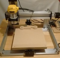
My first project was to make some eccentric clamps to hopefully hold down my work pieces. I created the parts in Fusion 360 and used it to generate the gcode, too. I think my parameters were a bit off, because it didn't cut all the way through the MDF. I was able to cut the pieces free using my pocket knife and clean them up with a bit of sanding. So far, they work pretty good.


Update: 1/28/2017
Up to this point, I had made several artistic cuts with this machine, but I'm wanting to move into something that requires more dimensional accuracy. I decided to run a test cut of concentric squares to see how accurate the machine really was. The pattern started with a square 7.5" wide, and each subsequent square was 0.5" smaller, all the way down to a 0.5" square in the center. I used Fusion 360 to lay out the squares, and used a Trace tool path to cut 0.02" deep along the squares.
After I ran the job, I measured each of the squares and they all appeared to be 0.25" inset from each other, as expected. However, when I measured the outermost square, it measured 1/16" larger than it should have. I did quite a bit of digging/searching but was having trouble finding anyone with similar issues until I finally found this thread:
Travel distance accuracy off by 1% in Ox Metal build. >Problem solved<
I positioned the machine near the front-left corner of the bed and, using a rigid straight edge to extend down to the bed, marked the current position. I then told the machine to move 150 mm (according to GrblPanel) to the right and marked that position. I did the same along the Y and Z axes, and then measured the distance the machine actually moved. Turns out, it was moving 151 mm in each direction. I then ran the numbers through the Rep Rap calculator mentioned in the above thread to find my new steps/mm values. With the new numbers, things seem to be working well. One thing I've noticed, though, is that I think I'm seeing a little bit of rounding error in GrblPanel (shown in the screen shot below).


A second run of the concentric squares test showed a much more accurate travel distance. I think I'm ready to have a go at the project I initially bought this machine for. Stay tuned for more updates!
Jim's C-Beam Machine Build
Build in 'X/Y Table Style CNC Mill' published by Jim_H, Jan 29, 2017.
This machine is fantastic. Teamed up with Fusion 360, Inkscape, and GrblPanel, I'm well on my way towards making at least one Christmas gift this year. I had some frustrating times during the build, mainly with getting everything to go together square, but overall it was fun. I can see that I'm going to need to be a bit creative in order to max out the work area for this machine so that I can produce the product I bought it for, but it will be able to do so much more for me as well.
-
-
Build Author Jim_H, Find all builds by Jim_H
-
- Loading...
-
Build Details
- Build License:
-
- CC - Attribution - CC BY
Reason for this Build
I have several projects that I would love to bring into existence, and this machine seemed like the perfect gateway into CNC routing. -
Parts list
Qty Part Name Part Link Comments 1 C-Beam Machine Parts Bundle w/ steppers http://openbuildspartstore.com/c-beam-machine-mechanical-... Link 1 DeWalt DWP611 Router Link Amazon 1 Power Supply - 24V 14.6A http://openbuildspartstore.com/24v-14-6a-power-supply/ Link 1 CNC xPro v2 Controller Board http://openbuildspartstore.com/cnc-xpro-v2-controller-ste... Link 1 Pen Holder http://www.openbuilds.com/projectresources/c-beam-machine... Link Used for calibration. Printed with 30% infill. 1 Router Mount Shim http://www.openbuilds.com/projectresources/dewalt-router-... Link